EP2878825A2 - Description géométrique de pale pour rotor - Google Patents
Description géométrique de pale pour rotor Download PDFInfo
- Publication number
- EP2878825A2 EP2878825A2 EP13816350.6A EP13816350A EP2878825A2 EP 2878825 A2 EP2878825 A2 EP 2878825A2 EP 13816350 A EP13816350 A EP 13816350A EP 2878825 A2 EP2878825 A2 EP 2878825A2
- Authority
- EP
- European Patent Office
- Prior art keywords
- blade
- point
- profile
- plane
- accordance
- Prior art date
- Legal status (The legal status is an assumption and is not a legal conclusion. Google has not performed a legal analysis and makes no representation as to the accuracy of the status listed.)
- Granted
Links
Images


Classifications
-
- F—MECHANICAL ENGINEERING; LIGHTING; HEATING; WEAPONS; BLASTING
- F03—MACHINES OR ENGINES FOR LIQUIDS; WIND, SPRING, OR WEIGHT MOTORS; PRODUCING MECHANICAL POWER OR A REACTIVE PROPULSIVE THRUST, NOT OTHERWISE PROVIDED FOR
- F03D—WIND MOTORS
- F03D1/00—Wind motors with rotation axis substantially parallel to the air flow entering the rotor
- F03D1/06—Rotors
- F03D1/0608—Rotors characterised by their aerodynamic shape
- F03D1/0633—Rotors characterised by their aerodynamic shape of the blades
-
- F—MECHANICAL ENGINEERING; LIGHTING; HEATING; WEAPONS; BLASTING
- F03—MACHINES OR ENGINES FOR LIQUIDS; WIND, SPRING, OR WEIGHT MOTORS; PRODUCING MECHANICAL POWER OR A REACTIVE PROPULSIVE THRUST, NOT OTHERWISE PROVIDED FOR
- F03D—WIND MOTORS
- F03D1/00—Wind motors with rotation axis substantially parallel to the air flow entering the rotor
-
- F—MECHANICAL ENGINEERING; LIGHTING; HEATING; WEAPONS; BLASTING
- F05—INDEXING SCHEMES RELATING TO ENGINES OR PUMPS IN VARIOUS SUBCLASSES OF CLASSES F01-F04
- F05B—INDEXING SCHEME RELATING TO WIND, SPRING, WEIGHT, INERTIA OR LIKE MOTORS, TO MACHINES OR ENGINES FOR LIQUIDS COVERED BY SUBCLASSES F03B, F03D AND F03G
- F05B2240/00—Components
- F05B2240/20—Rotors
- F05B2240/21—Rotors for wind turbines
- F05B2240/221—Rotors for wind turbines with horizontal axis
- F05B2240/2213—Rotors for wind turbines with horizontal axis and with the rotor downwind from the yaw pivot axis
-
- Y—GENERAL TAGGING OF NEW TECHNOLOGICAL DEVELOPMENTS; GENERAL TAGGING OF CROSS-SECTIONAL TECHNOLOGIES SPANNING OVER SEVERAL SECTIONS OF THE IPC; TECHNICAL SUBJECTS COVERED BY FORMER USPC CROSS-REFERENCE ART COLLECTIONS [XRACs] AND DIGESTS
- Y02—TECHNOLOGIES OR APPLICATIONS FOR MITIGATION OR ADAPTATION AGAINST CLIMATE CHANGE
- Y02E—REDUCTION OF GREENHOUSE GAS [GHG] EMISSIONS, RELATED TO ENERGY GENERATION, TRANSMISSION OR DISTRIBUTION
- Y02E10/00—Energy generation through renewable energy sources
- Y02E10/70—Wind energy
- Y02E10/72—Wind turbines with rotation axis in wind direction
Definitions
- the present invention refers to renewable energy generation, particularly those taking advantage of fluid kinetic energy.
- the present invention refers more specifically to the non-conventional design of the shape of a rotor blade belonging to a machine which generates power from the transformation of kinetic energy found in moving fluids.
- US2011/0070094 A1 describes an invention whose shape possesses a curvature which under principles different than aerodynamic forces, such as area reduction and Newton's third law of action reaction, prompt rotational blade movement, in addition, its cross-section is generated by the constant thickness sheet which channels fluid within the concave surface, in contrast to the cross-section of the present invention which uses a variable aerodynamic profile as a function of taking advantage of fluid-dynamic forces generated once the fluid passes through the inferior and superior zone of the profile.
- Non-conventional blade category CN101846042A and JP2010261431A , which have no similarity whatsoever with the operation or disposition of the present invention, and whose only relationship with the present invention lies in the implementation of non-conventional blade shapes of wind power generators.
- the present invention comprises a solution to some of the problems and needs of the low-scale wind power generation industry, wherein current worldwide equipment installed offer in their vast majority efficiencies ranging anywhere between 20 to 30%; said value expected to be increased with new technologies and design methodologies.
- the present invention is directed precisely to increase said efficiency, reaching efficiency values between 45 and 55%.
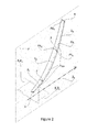
- the present invention discloses a blade for the generation of electrical energy stemming from the transformation of kinetic energy of a fluid, in rotational movement. Said rotational movement is moved to a central horizontal axis which may be coupled to an electric generator. Said horizontal axis is found defined by a Cartesian axis Z 0 which together with Cartesian axes X 0 Y 0 , form a global orthogonal framework of clearance planes.
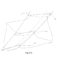
- Blade (e) has a particular geometrical shape which extends along axis Z 0 , moving away thereof as it continues to develop, and is limited longitudinally by Base (a) and Tip (b) , whose connection is obtained by a series of sectional and constant curvatures called Sectional Neutral Axes En i which generate all together a continuous or discontinuous primary curvature called Primary Neutral Axis En. Cross-sectionally, it is found limited by an Attack Edge (f) and an Escape Edge (d), which when joined by one or two continuous curves which connect several points, amongst them the point corresponding to the attack edge and the escape edge, form an Aerodynamic Profile PA ij having a variable or constant thickness. The volume defined by these five borders ( Base, Tip, Attack Edge, Escape Edge, Aerodynamic Profile ) generates the shape of the blade.
- the main geometrical feature of the blade is the curvature, defined by the Sectional Neutral Axes En i , which as mentioned above, when joined form the Primary Neutral Axis En whose curvature length is given by L, which may lie in the range of 0.01 m ⁇ L ⁇ 30 m.
- L which may lie in the range of 0.01 m ⁇ L ⁇ 30 m.
- Pc ij are joined; these points are constructed along the bottom curve describing aerodynamic profile PA ij, at a distance of c /4 from the attack edge point, c being the length of the aerodynamic profile cord.
- Said Primary Neutral Axis En is included within plane P , which coincides with the X 0 Z 0 plane.
- the initial point of Primary Neutral Axis En the base, is located by an auxiliary reference framework X 1 Y 1 Z 1 ; initiaitng at the intersection of plane X 1 Y 1 which is parallel to plane X 0 Y 0 and perpendicular to the rotation axis Z 0 ; with plane Y 1 Z 1 which is parallel to plane Y 0 Z 0 ; and to plane X 1 Z 1 which coincides with plane X 0 Z 0 and thus with plane P , if the preferred embodiment is had.
- This intersection point 1 between the auxiliary planes is where Primary Neutral Axis En begins and is also identified as the initial point of the first of three division sections of En .
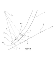
- the first section of division L 1 corresponds, in the blade's preferred embodiment, to 20% of L ; however, it may range between 0.15 * L ⁇ L 1 ⁇ 0.25 * L. This section is limited by points 1 and 2, whereby the latter is found towards the end of the length of L 1 over Sectional Neutral Axis En 1 .
- the second division section is defined by L 2 ; this section begins at point 2 and ends at point 3 located over Sectional Neutral Axis En 2 , in accordance to the preferred embodiment, this section has a length corresponding to 40% of L , but however it may vary between 0. 3 * L ⁇ L 2 ⁇ 0.5 * L.
- the last division section of the blade corresponds to L 3 and is limited by points 3 and 4; its length, as defined in the preferred embodiment is 40% of L , and like the other sections has a length between 0.3 * L ⁇ L 3 ⁇ 0.5 * L .
- the different arches defining each one of these sections are tangents at each one of the connection points, i.e., section L 1 is tangent to section L 2 at point 2 and section L 2 is tangent to section L 3 at point 3 .
- the shape of the blade undergoes a series of variations in its cross-section, which develop along the Primary Neutral Axis En from point 1 to point 4 and which like curvature L, these variations are analyzed at the same three sections L 1 L 2 L 3 .
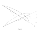
- the first variation evidenced is the length of the cross-section, seen as the decrease or increase of the length of cord c of aerodynamic profile PA ij .
- the length of said cross section is bound by ranges 0,05 * L ⁇ c 11 ⁇ 0,3 * L and 0,01 * L ⁇ c 33 ⁇ 0,3 * L , for aerodynamic profiles located at the base and tip of the blade, respectively.
- the second geometrical variation corresponds to a torsion which varies along Primary Neutral Axis En from point 1 to point 4 and which like curvature L, these variations are analyzed at the same three sections L 1 L 2 L 3 .
- This torsion is measured as a function of angle ⁇ ij which is formed between cord c of each PA ij profile and a perpendicular axis u to plane P which intersects Primary Neutral Axis En at point Pc ij .
- This angle way be both positive as well as negative, having angle 0° as an inflection point, which is formed when the u axis is parallel to the c cord.
- a positive angle exists when said angle grows clockwise and negative when counter-clockwise.
- the torsion angle may range between the following values, -38° ⁇ ⁇ i ⁇ 148° and the tip's torsion angle may range between -46° ⁇ ⁇ i ⁇ 40°. However, in the preferred embodiment the torsion is found between -31° ⁇ ⁇ i ⁇ 30° and -44° ⁇ ⁇ i ⁇ 16° for the base and tip, respectively.
- said torsion lies in the following ranges: 5° ⁇ ⁇ i ⁇ 25° and - 5° ⁇ ⁇ i ⁇ 15°, for the base and tip respectively.
- the present invention discloses a blade for electric power generation stemming from the transformation of a fluid's kinetic energy into rotational movement, wherein the capacity of kinetic energy transformation into rotation movement is directly correlated to the effective contact area between the blade and air flow.
- the present invention provides an increase of said effective area in contrast to a conventional flat blade, given its curved shape allows that for an equal effective diameter, a greater contact surface can be provided and thus a greater amount of energy generated.
- the blade's curvature herein allows for the kinetic energy found in the fluid's flow to be used in a greater proportion in contrast to that obtained using a conventional mainly flat-shaped blade.
- air flow impacting the blade does not do so perpendicularly as usually happens in conventional designs, wherein the greater part of the flow energy is transformed into drag forces associated to the pressure of impact, but instead, the flow impacting the blade does so at an angle with respect to the blade allowing for the flow to acquire velocity components which are used in kinetic energy transformation of the flow into rotational movement.
- the present invention discloses a blade for the generation of electrical power from the transformation of a fluid's kinetic energy into rotation movement. Said rotational movement is moved to a central horizontal axis which may be coupled to an electrical generator. This rotation horizontal axis is defined by a Cartesian axis Z 0 which together with Cartesian axes X 0 Y 0 , form a global orthogonal framework of clearance planes.
- blade (e) of the present invention having a particular geometrical shape which extends along axis Z 0 , moving away thereof as it continues to develop, and is limited longitudinally by Base (a) and Tip (b), whose connection is obtained by a series of sectional and constant curvatures called Sectional Neutral Axes En i which generate all together a continuous or discontinuous primary curvature called Primary Neutral Axis En .
- the curvature of the Primary Neutral Axis En may be continuous or discontinuous, it is necessary, for the latter, divide its length in different sections which allows to characterize the invention in continuous curvatures or Sectional Neutral Axes En i .
- the number of sections is one (1) for continuous Primary Neutral Axes En and at least two (2) for discontinuous Primary Neutral Axes En, wherein L 2 comprises 50% of L and L 3 the other 50%.
- the blade is divided into three (3) sections represented by Sectional Neutral Axes En 1 , En 2 , En 3 found between points 1 - 2; 2 - 3; and 3 - 4.
- This section corresponds to the base zone, where the blade is attached to the horizontal rotation axis.
- plane A is located and having an angle XY ° 1 with plane X 1 Y 1 , said angle ranging between 0° ⁇ XY ° 1 ⁇ 90°.
- its preferred value ranging from 0° ⁇ XY ° 1 ⁇ 40° and its greatest efficiency range between 10° ⁇ XY ° 1 ⁇ 20°.
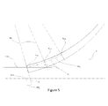
- section En 1 is observed formed by at least three (3) cross-sections, whose geometrical shape is an aerodynamic profile PA ij, named PA 11 , PA 12 y PA 13 .
- Each one of these profiles are found on a plane perpendicular to En 1 , the first plane A corresponds to profile PA 11 and located at point 1; the second plane B belongs to profile PA 12 and its location is at sectional neutral axis En 1 at an intermediate point between 1 and 2; at the third plane D, the aerodynamic profile PA 13 is found and is located at point 2.
- the solid having the geometric shape of the invention is generated at the base zone.
- this first section demonstrates a progressive change in its transverse length; this is due to the fact that cord c suffers an increase in size as it moves away from the beginning of the En 1 curve at point 1, where the cord shows values of 0,082 * L , 0,092 * L ,0,099 * L , for profiles PA 11 , PA 12 and PA 13 , respectively.
- this section may demonstrate progressive or regressive changes or a combination thereof in cord length, provided they are within the following ranges: 0,05 * L ⁇ c 11 ⁇ 0,3 * L; 0,046 * L ⁇ c 12 ⁇ 0,3 * L ; 0,042 * L ⁇ c 13 > 0,3 * L .
- each aerodynmic profile PA ij making part of section En 1 has an inclination angle ⁇ ij ( ⁇ 11 ⁇ 12 ⁇ 13 ) formed between cord c of each P A ij profile and u axis.
- the first aerodynamic profile in this section may lie between the following values, -30° ⁇ ⁇ 11 ⁇ 120° and the profile torsion angle and point 2 may lie between -34° ⁇ ⁇ 13 ⁇ 105°.
- said torsion is limited by the following ranges 5° ⁇ ⁇ i ⁇ 25° and 1° ⁇ ⁇ i ⁇ 19°, for profiles ⁇ 11 and ⁇ 13 , respectively (also see Figure 5 ).
- This section corresponds to the internal zone, wherein the greatest percentage of aerodynamic forces that the blade generates in its entirety are concentrated.
- Section En 2 is made up of at least three (3) equidistant cross-sections, whose geometric shape is an aerodynamic profile PA ij , called PA 21 , PA 22 y PA 23 .
- Each one of these profiles is found on a plane perpendicular to En 2 ; the first plane E corresponds to profile PA 21 and is located at point 2 ; the second plane F corresponds to profile PA 22 and it is located on sectional neutral axis En 2 at an intermediate point between 2 and 3 ; aerodynamic profile PA 23 is located on plane G and is located on point 3 .
- the solid having the geometric shape of the invention is generated in the internal zone of the blade.
- This second section in contrast to the first shows two sectional changes in its configuration of greatest performance; the first being a progressive change in the length of cord c from point 2 up to near the central point of curvature En 2 .
- This point preferably located on plane F is considered the inflection point of the cord of the section's aerodynamic profiles, since from it, cord c of the cross-sections describe a regressive behavior and its size begins to decrease until point 3.
- the cord has a value of 0,099 * L, 0,104 * L ,0,094 * L , for profiles PA 21 , PA 22 and PA 23 , respectively.
- this section may show progressive or regressive changes or combinations thereof in cord length, provided they are within the following ranges: 0,042 * L ⁇ c 21 ⁇ 0,3 * L ; 0,034 * L ⁇ c 22 ⁇ 0,3 * L ; 0,026 * L ⁇ c 23 ⁇ 0,3 * L.
- Each aerodynamic profile PA ij making part of section En 2 has an inclination angle ⁇ ij ( ⁇ 21 ⁇ 22 ⁇ 23 ) formed between cord c and each PA ij profile and the u axis.
- the first aerodynamic profile of this section may lie within the following values, -34° ⁇ ⁇ 21 ⁇ 105° and the final profile torsion angle at point 3 may range between -41° ⁇ ⁇ i ⁇ 60°. However, in its configuration of greatest performance, said torsion is bound by the ranges 1° ⁇ ⁇ i ⁇ 19° and - 5° ⁇ ⁇ i ⁇ 13°, for profiles ⁇ 21 and ⁇ 23 , respectively.
- This section corresponds to the external zone, and here is where the greatest rotational velocity components are found, and therefore its inertia must be the least in order to reduce stresses; this is obtained by decreasing the size of the aerodynamic profiles which make part of the section.
- section En 3 is shown which is made up of at least three (3) equidistant cross-sections, whose geometric shape is an aerodynamic profile PA ij , called PA 31 , PA 32 y PA 33 .
- Each one of these profiles is found on a plane perpendicular to En 3 ; the first plane H corresponds to profile PA 31 and is located at point 3; the second plane I corresponds to profile PA 32 and is located on sectional neutral axis En 3 at an intermediate point between 3 and 4 ; aerodynamic profile PA 33 is located on plane J and is located on point 4 .
- the solid having the geometric shape of the invention is generated in the external zone.
- This third and preferably last section develops a regressive change in its transverse length for the embodiment of greatest performance; this is due to the fact that cord c decreases its size as it moves away from the beginning of curve En 3 at point 3.
- the cord has a value of 0,094 * L , 0,080 * L ,0,070 * L , for profiles PA 31 , PA 32 and PA 33 , respectively.
- this section may show progressive or regressive changes or combinations thereof in cord length, provided they are within the following ranges: 0,026 * L ⁇ c 31 ⁇ 0,3 * L ; 0,018 * L ⁇ c 32 ⁇ 0,3 * L ; 0,01 * L ⁇ c 33 ⁇ 0,3 * L.
- Each aerodynamic profile PA ij making part of section En 3 has an inclination angle ⁇ ij ⁇ ( ⁇ 31 ⁇ 32 ⁇ 33 ) formed between cord c of each PA ij profile and u axis.
- the first aerodynamic profile in this section may lie between the following values, -41° ⁇ ⁇ 31 ⁇ 60° and the profile torsion angle at point 4 may lie between -44° ⁇ ⁇ 33 ⁇ 16°.
- said torsion is limited by the following ranges 5° ⁇ ⁇ i ⁇ 13° and - 5° ⁇ ⁇ i ⁇ 15°, for profiles ⁇ 31 and ⁇ 33 , respectively.
- the blades were designed in order to operate optimally both at low as well as high speeds with an optimal rotor tip speed ratio (TSR) of 6; i.e., the rotor must rotate at an RPM such that the tangential speed of the blade tip is 6 times the velocity of the fluid it faces.
- TSR rotor tip speed ratio
- the following graph shows the blade's Cp (coefficient of power) for different speeds and different TSR. This demonstrated that efficiencies (Cp) over 40% for TSR between 4 and 7 are obtained. However, the greatest efficiency is gained for TSR between 5 and 6, the range in which the system is calculated will operate, as demonstrated in the following graph. It is reminded that the maximum efficiency a rotor can achieve is 59.3%, which corresponds to the Betz limit which is 0.593.
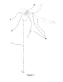
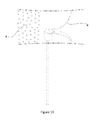
- This array comprises a total of three blades (e) radially placed at a 120° angle from each other, said blades (e) are fixed in the direction stated above by a support system (g); said support system (g) is attached to an electrical energy generating system having a rotation axis (h) (in the same location as imaginary rotation axis Z 0 ) allowing for rotational movement of the blades (e) in the direction illustrated by the vectors (m); a shaft (j) located vertically which elevates the system up to a determined height, the electrical energy generating system is attached thereto which possesses a rotation axis (h) from which the support system (g) is attached which in turn holds the blades (e); a keel (i) attached to the shaft (j) which purpose is to cover the frontal zone of the system in order to smooth the fluid's flow (
- the present invention's operation is shown under the configuration set forth above, comprising the transformation of linear kinetic energy possessed by fluid (k) in movement, in rotational movement (m) of the blades (e) when these are impacted by air.
- the rotation process begins when the air impacts the attack edge (f) and moves through the bottom and top surfaces comprising the aerodynamic profiles PA ij of blade (e), until arriving finally to the escape edge (d).
- the air passing through the top zone acquires greater speed than the air passing through the bottom zone, thus generating a pressure differential on these surfaces, which finally translates in a lift force having a component in the rotation direction (m) thus generating torque with respect to the rotation axis (h).
- the advantage offered by this invention with respect to prior art is the capacity of transforming said kinetic energy in rotational movement which is directly correlated to the effective contact area between the blade (e) and the air flow (k); thus the invention presents an increase of said effective area in comparison to a conventional flat blade, this because of its curved shape which allows that for a same effective diameter, a greater contact surface can be made and therefore generating greater amount of energy.
- the curvature of blade (e) allows for kinetic energy possessed by the flow (k) of the fluid in movement to be used in greater proportion than that obtained using a conventional flat-shaped blade.
- the above is true given the air flow impacting the blade is not perpendicular as usually happens in conventional designs, wherein the greater part of the flow's energy is transformed into drag forces associated to impact pressure, and in contrast, the flow impacts blade (e) at an angle with respect to the blade (e) allowing for the flow to acquire speed components which are used in transforming flow kinetic energy in rotational movement (m).
Landscapes
- Engineering & Computer Science (AREA)
- Life Sciences & Earth Sciences (AREA)
- Sustainable Development (AREA)
- Sustainable Energy (AREA)
- Chemical & Material Sciences (AREA)
- Combustion & Propulsion (AREA)
- Mechanical Engineering (AREA)
- General Engineering & Computer Science (AREA)
- Physics & Mathematics (AREA)
- Fluid Mechanics (AREA)
- Wind Motors (AREA)
- Structures Of Non-Positive Displacement Pumps (AREA)
Applications Claiming Priority (2)
| Application Number | Priority Date | Filing Date | Title |
|---|---|---|---|
| CO12118162A CO6860304A1 (es) | 2012-07-13 | 2012-07-13 | Descripción geometrica pala para rotor |
| PCT/IB2013/055783 WO2014009934A2 (fr) | 2012-07-13 | 2013-07-13 | Description géométrique de pale pour rotor |
Publications (3)
| Publication Number | Publication Date |
|---|---|
| EP2878825A2 true EP2878825A2 (fr) | 2015-06-03 |
| EP2878825A4 EP2878825A4 (fr) | 2016-04-27 |
| EP2878825B1 EP2878825B1 (fr) | 2021-04-14 |
Family
ID=49916611
Family Applications (1)
| Application Number | Title | Priority Date | Filing Date |
|---|---|---|---|
| EP13816350.6A Active EP2878825B1 (fr) | 2012-07-13 | 2013-07-13 | Description géométrique de pale pour rotor |
Country Status (6)
| Country | Link |
|---|---|
| US (1) | US10184447B2 (fr) |
| EP (1) | EP2878825B1 (fr) |
| CN (1) | CN104838147B (fr) |
| CO (1) | CO6860304A1 (fr) |
| MX (1) | MX365671B (fr) |
| WO (1) | WO2014009934A2 (fr) |
Cited By (1)
| Publication number | Priority date | Publication date | Assignee | Title |
|---|---|---|---|---|
| JP2018119483A (ja) * | 2017-01-26 | 2018-08-02 | 国立大学法人鳥取大学 | 翼及びそれを用いた風車 |
Family Cites Families (12)
| Publication number | Priority date | Publication date | Assignee | Title |
|---|---|---|---|---|
| DE3047501C2 (de) | 1980-12-17 | 1983-03-10 | Hilarius 4300 Essen Drzisga | Windturbine |
| DE3130257A1 (de) * | 1981-07-31 | 1983-02-17 | Louis L. 7570 Baden-Baden Lepoix | Vorrichtung zur umwandlung der kinetischen energie des windes in eine andere energieart, vorzugsweise in elektrische energie |
| DE4030559A1 (de) * | 1990-09-27 | 1992-04-02 | Schubert Werner | Windturbine zur besseren ausnutzung der windkraft |
| DE10307682A1 (de) | 2002-06-05 | 2004-01-08 | Aloys Wobben | Rotorblatt einer Windenergieanlage |
| AU2006270023B2 (en) | 2005-07-15 | 2011-06-16 | Xzeres Corp. | Wind turbine and method of manufacture |
| FR2930300B1 (fr) | 2008-04-22 | 2011-10-21 | Nheolis | Pale pour appareil de generation d'energie a partir d'un ecoulement fluidique pouvant etre de l'air ou de l'eau |
| JP5365959B2 (ja) | 2009-05-11 | 2013-12-11 | 正憲 麻生 | 翼角調整機能付平板翼片持支持式(うちわ式)多翼プロペラ形風車 |
| CN101846042A (zh) | 2009-06-06 | 2010-09-29 | 郑重胜 | 高效的叶片后置型风力发电装置 |
| ES2516742T3 (es) | 2010-03-18 | 2014-10-31 | Nordex Energy Gmbh | Pala de rotor para una instalación de energía eólica |
| US9790795B2 (en) | 2010-10-22 | 2017-10-17 | Mitsubishi Heavy Industries, Ltd. | Wind turbine blade, wind power generation system including the same, and method for designing wind turbine blade |
| US20120020803A1 (en) * | 2011-02-14 | 2012-01-26 | Paul Lees | Turbine blades, systems and methods |
| US20130315746A1 (en) * | 2012-05-26 | 2013-11-28 | Sinomatech Wind Power Blade Co., Ltd. | Wind blades and producing method thereof |
-
2012
- 2012-07-13 CO CO12118162A patent/CO6860304A1/es active IP Right Grant
-
2013
- 2013-07-13 EP EP13816350.6A patent/EP2878825B1/fr active Active
- 2013-07-13 US US14/414,276 patent/US10184447B2/en active Active
- 2013-07-13 CN CN201380047701.4A patent/CN104838147B/zh not_active Expired - Fee Related
- 2013-07-13 MX MX2014016115A patent/MX365671B/es active IP Right Grant
- 2013-07-13 WO PCT/IB2013/055783 patent/WO2014009934A2/fr not_active Ceased
Cited By (1)
| Publication number | Priority date | Publication date | Assignee | Title |
|---|---|---|---|---|
| JP2018119483A (ja) * | 2017-01-26 | 2018-08-02 | 国立大学法人鳥取大学 | 翼及びそれを用いた風車 |
Also Published As
| Publication number | Publication date |
|---|---|
| CN104838147A (zh) | 2015-08-12 |
| EP2878825A4 (fr) | 2016-04-27 |
| EP2878825B1 (fr) | 2021-04-14 |
| MX365671B (es) | 2019-06-10 |
| WO2014009934A2 (fr) | 2014-01-16 |
| CO6860304A1 (es) | 2014-02-10 |
| MX2014016115A (es) | 2015-07-14 |
| US10184447B2 (en) | 2019-01-22 |
| US20150219069A1 (en) | 2015-08-06 |
| CN104838147B (zh) | 2019-02-22 |
| WO2014009934A3 (fr) | 2014-03-20 |
Similar Documents
| Publication | Publication Date | Title |
|---|---|---|
| KR20150095587A (ko) | 수직축 풍력 터빈 로터 및 날개 | |
| JP5314851B2 (ja) | 圧縮機の第2フェーズ用のロータブレード | |
| Setoguchi et al. | A review of impulse turbines for wave energy conversion | |
| EP2141355A2 (fr) | Aubes d'éolienne avec des courbures multiples | |
| US20110150664A1 (en) | Aeroacoustic rotor blade for a wind turbine, and wind turbine equipped therewith | |
| Wong et al. | The design and flow simulation of a power-augmented shroud for urban wind turbine system | |
| EP2169217A1 (fr) | Pale pour éoliennes | |
| RU2557966C2 (ru) | Устройство генерирования энергии из текучей среды и лопасть, использующаяся в нем | |
| CA2598877A1 (fr) | Pale d'eolienne cambree et technique de fabrication | |
| CN108138747B (zh) | 确定和控制定速风力涡轮机叶片的攻角的方法 | |
| GB2415749A (en) | Exhaust gas diffuser | |
| CN101029647B (zh) | 用于压缩机第九级的转子叶片 | |
| EP2878825A2 (fr) | Description géométrique de pale pour rotor | |
| Shehata et al. | Wind turbine tip deflection control using bio-inspired tubercle leading edges: Analysis of potential designs | |
| EP3120016B1 (fr) | Dispositifs mécaniques rotatifs à axes d'écoulement transversal avec zone balayée dynamique augmentée | |
| KR102499973B1 (ko) | 수직축 풍차 및 풍력 발전 장치 | |
| EP2878806A1 (fr) | Pale d'éolienne et procédé pour sa fabrication | |
| JP2018119483A (ja) | 翼及びそれを用いた風車 | |
| KR100752755B1 (ko) | 풍력 발전기의 수직날개 및 그 성형방법 | |
| US12421933B1 (en) | Low speed multiblade wind turbine | |
| Dominguez Fernandez et al. | Design of a hydroformed metal blade for vertical-axis wind turbines | |
| KR101346085B1 (ko) | 축류형 압축기 동익단의 최적화 설계기법 및, 이 설계기법에 의해 제작된 축류형 압축기 동익 | |
| Ghane et al. | Numerical Simulation of Micro Wind Turbine for Low Speed Applications. | |
| Gupta | Aerodynamic and structural analyses of the 5 MW wind turbine using BEM and lifting line theories | |
| Rhenals-Julio et al. | FLUID DYNAMIC DESIGN OF A VERTICAL AXIS WIND TURBINE ROTOR UNDER LOW WIND SPEED |
Legal Events
| Date | Code | Title | Description |
|---|---|---|---|
| PUAI | Public reference made under article 153(3) epc to a published international application that has entered the european phase |
Free format text: ORIGINAL CODE: 0009012 |
|
| 17P | Request for examination filed |
Effective date: 20150213 |
|
| AK | Designated contracting states |
Kind code of ref document: A2 Designated state(s): AL AT BE BG CH CY CZ DE DK EE ES FI FR GB GR HR HU IE IS IT LI LT LU LV MC MK MT NL NO PL PT RO RS SE SI SK SM TR |
|
| AX | Request for extension of the european patent |
Extension state: BA ME |
|
| DAX | Request for extension of the european patent (deleted) | ||
| A4 | Supplementary search report drawn up and despatched |
Effective date: 20160331 |
|
| RIC1 | Information provided on ipc code assigned before grant |
Ipc: F04D 1/06 20060101AFI20160323BHEP |
|
| STAA | Information on the status of an ep patent application or granted ep patent |
Free format text: STATUS: REQUEST FOR EXAMINATION WAS MADE |
|
| STAA | Information on the status of an ep patent application or granted ep patent |
Free format text: STATUS: EXAMINATION IS IN PROGRESS |
|
| 17Q | First examination report despatched |
Effective date: 20180808 |
|
| GRAP | Despatch of communication of intention to grant a patent |
Free format text: ORIGINAL CODE: EPIDOSNIGR1 |
|
| STAA | Information on the status of an ep patent application or granted ep patent |
Free format text: STATUS: GRANT OF PATENT IS INTENDED |
|
| INTG | Intention to grant announced |
Effective date: 20201028 |
|
| GRAS | Grant fee paid |
Free format text: ORIGINAL CODE: EPIDOSNIGR3 |
|
| GRAA | (expected) grant |
Free format text: ORIGINAL CODE: 0009210 |
|
| STAA | Information on the status of an ep patent application or granted ep patent |
Free format text: STATUS: THE PATENT HAS BEEN GRANTED |
|
| AK | Designated contracting states |
Kind code of ref document: B1 Designated state(s): AL AT BE BG CH CY CZ DE DK EE ES FI FR GB GR HR HU IE IS IT LI LT LU LV MC MK MT NL NO PL PT RO RS SE SI SK SM TR |
|
| REG | Reference to a national code |
Ref country code: GB Ref legal event code: FG4D |
|
| REG | Reference to a national code |
Ref country code: CH Ref legal event code: EP |
|
| REG | Reference to a national code |
Ref country code: DE Ref legal event code: R096 Ref document number: 602013076917 Country of ref document: DE |
|
| REG | Reference to a national code |
Ref country code: IE Ref legal event code: FG4D |
|
| REG | Reference to a national code |
Ref country code: AT Ref legal event code: REF Ref document number: 1382619 Country of ref document: AT Kind code of ref document: T Effective date: 20210515 |
|
| REG | Reference to a national code |
Ref country code: LT Ref legal event code: MG9D |
|
| REG | Reference to a national code |
Ref country code: AT Ref legal event code: MK05 Ref document number: 1382619 Country of ref document: AT Kind code of ref document: T Effective date: 20210414 |
|
| REG | Reference to a national code |
Ref country code: NL Ref legal event code: MP Effective date: 20210414 |
|
| PG25 | Lapsed in a contracting state [announced via postgrant information from national office to epo] |
Ref country code: NL Free format text: LAPSE BECAUSE OF FAILURE TO SUBMIT A TRANSLATION OF THE DESCRIPTION OR TO PAY THE FEE WITHIN THE PRESCRIBED TIME-LIMIT Effective date: 20210414 Ref country code: LT Free format text: LAPSE BECAUSE OF FAILURE TO SUBMIT A TRANSLATION OF THE DESCRIPTION OR TO PAY THE FEE WITHIN THE PRESCRIBED TIME-LIMIT Effective date: 20210414 Ref country code: FI Free format text: LAPSE BECAUSE OF FAILURE TO SUBMIT A TRANSLATION OF THE DESCRIPTION OR TO PAY THE FEE WITHIN THE PRESCRIBED TIME-LIMIT Effective date: 20210414 Ref country code: BG Free format text: LAPSE BECAUSE OF FAILURE TO SUBMIT A TRANSLATION OF THE DESCRIPTION OR TO PAY THE FEE WITHIN THE PRESCRIBED TIME-LIMIT Effective date: 20210714 Ref country code: AT Free format text: LAPSE BECAUSE OF FAILURE TO SUBMIT A TRANSLATION OF THE DESCRIPTION OR TO PAY THE FEE WITHIN THE PRESCRIBED TIME-LIMIT Effective date: 20210414 Ref country code: HR Free format text: LAPSE BECAUSE OF FAILURE TO SUBMIT A TRANSLATION OF THE DESCRIPTION OR TO PAY THE FEE WITHIN THE PRESCRIBED TIME-LIMIT Effective date: 20210414 |
|
| PG25 | Lapsed in a contracting state [announced via postgrant information from national office to epo] |
Ref country code: ES Free format text: LAPSE BECAUSE OF FAILURE TO SUBMIT A TRANSLATION OF THE DESCRIPTION OR TO PAY THE FEE WITHIN THE PRESCRIBED TIME-LIMIT Effective date: 20210414 Ref country code: PT Free format text: LAPSE BECAUSE OF FAILURE TO SUBMIT A TRANSLATION OF THE DESCRIPTION OR TO PAY THE FEE WITHIN THE PRESCRIBED TIME-LIMIT Effective date: 20210816 Ref country code: NO Free format text: LAPSE BECAUSE OF FAILURE TO SUBMIT A TRANSLATION OF THE DESCRIPTION OR TO PAY THE FEE WITHIN THE PRESCRIBED TIME-LIMIT Effective date: 20210714 Ref country code: PL Free format text: LAPSE BECAUSE OF FAILURE TO SUBMIT A TRANSLATION OF THE DESCRIPTION OR TO PAY THE FEE WITHIN THE PRESCRIBED TIME-LIMIT Effective date: 20210414 Ref country code: RS Free format text: LAPSE BECAUSE OF FAILURE TO SUBMIT A TRANSLATION OF THE DESCRIPTION OR TO PAY THE FEE WITHIN THE PRESCRIBED TIME-LIMIT Effective date: 20210414 Ref country code: SE Free format text: LAPSE BECAUSE OF FAILURE TO SUBMIT A TRANSLATION OF THE DESCRIPTION OR TO PAY THE FEE WITHIN THE PRESCRIBED TIME-LIMIT Effective date: 20210414 Ref country code: LV Free format text: LAPSE BECAUSE OF FAILURE TO SUBMIT A TRANSLATION OF THE DESCRIPTION OR TO PAY THE FEE WITHIN THE PRESCRIBED TIME-LIMIT Effective date: 20210414 Ref country code: IS Free format text: LAPSE BECAUSE OF FAILURE TO SUBMIT A TRANSLATION OF THE DESCRIPTION OR TO PAY THE FEE WITHIN THE PRESCRIBED TIME-LIMIT Effective date: 20210814 Ref country code: GR Free format text: LAPSE BECAUSE OF FAILURE TO SUBMIT A TRANSLATION OF THE DESCRIPTION OR TO PAY THE FEE WITHIN THE PRESCRIBED TIME-LIMIT Effective date: 20210715 |
|
| REG | Reference to a national code |
Ref country code: DE Ref legal event code: R097 Ref document number: 602013076917 Country of ref document: DE |
|
| PG25 | Lapsed in a contracting state [announced via postgrant information from national office to epo] |
Ref country code: SK Free format text: LAPSE BECAUSE OF FAILURE TO SUBMIT A TRANSLATION OF THE DESCRIPTION OR TO PAY THE FEE WITHIN THE PRESCRIBED TIME-LIMIT Effective date: 20210414 Ref country code: SM Free format text: LAPSE BECAUSE OF FAILURE TO SUBMIT A TRANSLATION OF THE DESCRIPTION OR TO PAY THE FEE WITHIN THE PRESCRIBED TIME-LIMIT Effective date: 20210414 Ref country code: CZ Free format text: LAPSE BECAUSE OF FAILURE TO SUBMIT A TRANSLATION OF THE DESCRIPTION OR TO PAY THE FEE WITHIN THE PRESCRIBED TIME-LIMIT Effective date: 20210414 Ref country code: EE Free format text: LAPSE BECAUSE OF FAILURE TO SUBMIT A TRANSLATION OF THE DESCRIPTION OR TO PAY THE FEE WITHIN THE PRESCRIBED TIME-LIMIT Effective date: 20210414 Ref country code: DK Free format text: LAPSE BECAUSE OF FAILURE TO SUBMIT A TRANSLATION OF THE DESCRIPTION OR TO PAY THE FEE WITHIN THE PRESCRIBED TIME-LIMIT Effective date: 20210414 Ref country code: RO Free format text: LAPSE BECAUSE OF FAILURE TO SUBMIT A TRANSLATION OF THE DESCRIPTION OR TO PAY THE FEE WITHIN THE PRESCRIBED TIME-LIMIT Effective date: 20210414 |
|
| PLBE | No opposition filed within time limit |
Free format text: ORIGINAL CODE: 0009261 |
|
| STAA | Information on the status of an ep patent application or granted ep patent |
Free format text: STATUS: NO OPPOSITION FILED WITHIN TIME LIMIT |
|
| REG | Reference to a national code |
Ref country code: CH Ref legal event code: PL |
|
| 26N | No opposition filed |
Effective date: 20220117 |
|
| GBPC | Gb: european patent ceased through non-payment of renewal fee |
Effective date: 20210714 |
|
| PG25 | Lapsed in a contracting state [announced via postgrant information from national office to epo] |
Ref country code: MC Free format text: LAPSE BECAUSE OF FAILURE TO SUBMIT A TRANSLATION OF THE DESCRIPTION OR TO PAY THE FEE WITHIN THE PRESCRIBED TIME-LIMIT Effective date: 20210414 |
|
| REG | Reference to a national code |
Ref country code: BE Ref legal event code: MM Effective date: 20210731 |
|
| PG25 | Lapsed in a contracting state [announced via postgrant information from national office to epo] |
Ref country code: LI Free format text: LAPSE BECAUSE OF NON-PAYMENT OF DUE FEES Effective date: 20210731 Ref country code: GB Free format text: LAPSE BECAUSE OF NON-PAYMENT OF DUE FEES Effective date: 20210714 Ref country code: CH Free format text: LAPSE BECAUSE OF NON-PAYMENT OF DUE FEES Effective date: 20210731 |
|
| PG25 | Lapsed in a contracting state [announced via postgrant information from national office to epo] |
Ref country code: IS Free format text: LAPSE BECAUSE OF FAILURE TO SUBMIT A TRANSLATION OF THE DESCRIPTION OR TO PAY THE FEE WITHIN THE PRESCRIBED TIME-LIMIT Effective date: 20210814 Ref country code: LU Free format text: LAPSE BECAUSE OF NON-PAYMENT OF DUE FEES Effective date: 20210713 Ref country code: FR Free format text: LAPSE BECAUSE OF NON-PAYMENT OF DUE FEES Effective date: 20210731 Ref country code: AL Free format text: LAPSE BECAUSE OF FAILURE TO SUBMIT A TRANSLATION OF THE DESCRIPTION OR TO PAY THE FEE WITHIN THE PRESCRIBED TIME-LIMIT Effective date: 20210414 |
|
| PG25 | Lapsed in a contracting state [announced via postgrant information from national office to epo] |
Ref country code: IT Free format text: LAPSE BECAUSE OF FAILURE TO SUBMIT A TRANSLATION OF THE DESCRIPTION OR TO PAY THE FEE WITHIN THE PRESCRIBED TIME-LIMIT Effective date: 20210414 Ref country code: IE Free format text: LAPSE BECAUSE OF NON-PAYMENT OF DUE FEES Effective date: 20210713 Ref country code: BE Free format text: LAPSE BECAUSE OF NON-PAYMENT OF DUE FEES Effective date: 20210731 |
|
| PG25 | Lapsed in a contracting state [announced via postgrant information from national office to epo] |
Ref country code: HU Free format text: LAPSE BECAUSE OF FAILURE TO SUBMIT A TRANSLATION OF THE DESCRIPTION OR TO PAY THE FEE WITHIN THE PRESCRIBED TIME-LIMIT; INVALID AB INITIO Effective date: 20130713 |
|
| PG25 | Lapsed in a contracting state [announced via postgrant information from national office to epo] |
Ref country code: CY Free format text: LAPSE BECAUSE OF FAILURE TO SUBMIT A TRANSLATION OF THE DESCRIPTION OR TO PAY THE FEE WITHIN THE PRESCRIBED TIME-LIMIT Effective date: 20210414 |
|
| PGFP | Annual fee paid to national office [announced via postgrant information from national office to epo] |
Ref country code: DE Payment date: 20230727 Year of fee payment: 11 |
|
| PG25 | Lapsed in a contracting state [announced via postgrant information from national office to epo] |
Ref country code: MK Free format text: LAPSE BECAUSE OF FAILURE TO SUBMIT A TRANSLATION OF THE DESCRIPTION OR TO PAY THE FEE WITHIN THE PRESCRIBED TIME-LIMIT Effective date: 20210414 |
|
| PG25 | Lapsed in a contracting state [announced via postgrant information from national office to epo] |
Ref country code: MT Free format text: LAPSE BECAUSE OF FAILURE TO SUBMIT A TRANSLATION OF THE DESCRIPTION OR TO PAY THE FEE WITHIN THE PRESCRIBED TIME-LIMIT Effective date: 20210414 |
|
| REG | Reference to a national code |
Ref country code: DE Ref legal event code: R119 Ref document number: 602013076917 Country of ref document: DE |
|
| PG25 | Lapsed in a contracting state [announced via postgrant information from national office to epo] |
Ref country code: DE Free format text: LAPSE BECAUSE OF NON-PAYMENT OF DUE FEES Effective date: 20250201 |
|
| PG25 | Lapsed in a contracting state [announced via postgrant information from national office to epo] |
Ref country code: TR Free format text: LAPSE BECAUSE OF FAILURE TO SUBMIT A TRANSLATION OF THE DESCRIPTION OR TO PAY THE FEE WITHIN THE PRESCRIBED TIME-LIMIT Effective date: 20210414 |