EP2878829A1 - Hydraulisches Druckversorgungssystem - Google Patents
Hydraulisches Druckversorgungssystem Download PDFInfo
- Publication number
- EP2878829A1 EP2878829A1 EP14187163.2A EP14187163A EP2878829A1 EP 2878829 A1 EP2878829 A1 EP 2878829A1 EP 14187163 A EP14187163 A EP 14187163A EP 2878829 A1 EP2878829 A1 EP 2878829A1
- Authority
- EP
- European Patent Office
- Prior art keywords
- pressure
- valve
- supply system
- pump
- bar
- Prior art date
- Legal status (The legal status is an assumption and is not a legal conclusion. Google has not performed a legal analysis and makes no representation as to the accuracy of the status listed.)
- Granted
Links
Images

Classifications
-
- F—MECHANICAL ENGINEERING; LIGHTING; HEATING; WEAPONS; BLASTING
- F15—FLUID-PRESSURE ACTUATORS; HYDRAULICS OR PNEUMATICS IN GENERAL
- F15B—SYSTEMS ACTING BY MEANS OF FLUIDS IN GENERAL; FLUID-PRESSURE ACTUATORS, e.g. SERVOMOTORS; DETAILS OF FLUID-PRESSURE SYSTEMS, NOT OTHERWISE PROVIDED FOR
- F15B11/00—Servomotor systems without provision for follow-up action ; Circuits therefor
- F15B11/16—Servomotor systems without provision for follow-up action ; Circuits therefor with two or more servomotors
- F15B11/161—Servomotor systems without provision for follow-up action ; Circuits therefor with two or more servomotors with sensing of servomotor demand or load
- F15B11/163—Servomotor systems without provision for follow-up action ; Circuits therefor with two or more servomotors with sensing of servomotor demand or load for sharing the pump output equally amongst users or groups of users, e.g. using anti-saturation, pressure compensation
-
- E—FIXED CONSTRUCTIONS
- E02—HYDRAULIC ENGINEERING; FOUNDATIONS; SOIL SHIFTING
- E02F—DREDGING; SOIL-SHIFTING
- E02F9/00—Component parts of dredgers or soil-shifting machines, not restricted to one of the kinds covered by groups E02F3/00 - E02F7/00
- E02F9/20—Drives; Control devices
- E02F9/22—Hydraulic or pneumatic drives
- E02F9/2221—Control of flow rate; Load sensing arrangements
- E02F9/2225—Control of flow rate; Load sensing arrangements using pressure-compensating valves
-
- F—MECHANICAL ENGINEERING; LIGHTING; HEATING; WEAPONS; BLASTING
- F15—FLUID-PRESSURE ACTUATORS; HYDRAULICS OR PNEUMATICS IN GENERAL
- F15B—SYSTEMS ACTING BY MEANS OF FLUIDS IN GENERAL; FLUID-PRESSURE ACTUATORS, e.g. SERVOMOTORS; DETAILS OF FLUID-PRESSURE SYSTEMS, NOT OTHERWISE PROVIDED FOR
- F15B2211/00—Circuits for servomotor systems
- F15B2211/20—Fluid pressure source, e.g. accumulator or variable axial piston pump
- F15B2211/205—Systems with pumps
- F15B2211/2053—Type of pump
- F15B2211/20538—Type of pump constant capacity
-
- F—MECHANICAL ENGINEERING; LIGHTING; HEATING; WEAPONS; BLASTING
- F15—FLUID-PRESSURE ACTUATORS; HYDRAULICS OR PNEUMATICS IN GENERAL
- F15B—SYSTEMS ACTING BY MEANS OF FLUIDS IN GENERAL; FLUID-PRESSURE ACTUATORS, e.g. SERVOMOTORS; DETAILS OF FLUID-PRESSURE SYSTEMS, NOT OTHERWISE PROVIDED FOR
- F15B2211/00—Circuits for servomotor systems
- F15B2211/30—Directional control
- F15B2211/31—Directional control characterised by the positions of the valve element
- F15B2211/3105—Neutral or centre positions
- F15B2211/3111—Neutral or centre positions the pump port being closed in the centre position, e.g. so-called closed centre
-
- F—MECHANICAL ENGINEERING; LIGHTING; HEATING; WEAPONS; BLASTING
- F15—FLUID-PRESSURE ACTUATORS; HYDRAULICS OR PNEUMATICS IN GENERAL
- F15B—SYSTEMS ACTING BY MEANS OF FLUIDS IN GENERAL; FLUID-PRESSURE ACTUATORS, e.g. SERVOMOTORS; DETAILS OF FLUID-PRESSURE SYSTEMS, NOT OTHERWISE PROVIDED FOR
- F15B2211/00—Circuits for servomotor systems
- F15B2211/50—Pressure control
- F15B2211/505—Pressure control characterised by the type of pressure control means
- F15B2211/50509—Pressure control characterised by the type of pressure control means the pressure control means controlling a pressure upstream of the pressure control means
- F15B2211/50536—Pressure control characterised by the type of pressure control means the pressure control means controlling a pressure upstream of the pressure control means using unloading valves controlling the supply pressure by diverting fluid to the return line
-
- F—MECHANICAL ENGINEERING; LIGHTING; HEATING; WEAPONS; BLASTING
- F15—FLUID-PRESSURE ACTUATORS; HYDRAULICS OR PNEUMATICS IN GENERAL
- F15B—SYSTEMS ACTING BY MEANS OF FLUIDS IN GENERAL; FLUID-PRESSURE ACTUATORS, e.g. SERVOMOTORS; DETAILS OF FLUID-PRESSURE SYSTEMS, NOT OTHERWISE PROVIDED FOR
- F15B2211/00—Circuits for servomotor systems
- F15B2211/50—Pressure control
- F15B2211/52—Pressure control characterised by the type of actuation
- F15B2211/528—Pressure control characterised by the type of actuation actuated by fluid pressure
-
- F—MECHANICAL ENGINEERING; LIGHTING; HEATING; WEAPONS; BLASTING
- F15—FLUID-PRESSURE ACTUATORS; HYDRAULICS OR PNEUMATICS IN GENERAL
- F15B—SYSTEMS ACTING BY MEANS OF FLUIDS IN GENERAL; FLUID-PRESSURE ACTUATORS, e.g. SERVOMOTORS; DETAILS OF FLUID-PRESSURE SYSTEMS, NOT OTHERWISE PROVIDED FOR
- F15B2211/00—Circuits for servomotor systems
- F15B2211/60—Circuit components or control therefor
- F15B2211/605—Load sensing circuits
- F15B2211/6051—Load sensing circuits having valve means between output member and the load sensing circuit
-
- F—MECHANICAL ENGINEERING; LIGHTING; HEATING; WEAPONS; BLASTING
- F15—FLUID-PRESSURE ACTUATORS; HYDRAULICS OR PNEUMATICS IN GENERAL
- F15B—SYSTEMS ACTING BY MEANS OF FLUIDS IN GENERAL; FLUID-PRESSURE ACTUATORS, e.g. SERVOMOTORS; DETAILS OF FLUID-PRESSURE SYSTEMS, NOT OTHERWISE PROVIDED FOR
- F15B2211/00—Circuits for servomotor systems
- F15B2211/60—Circuit components or control therefor
- F15B2211/65—Methods of control of the load sensing pressure
- F15B2211/653—Methods of control of the load sensing pressure the load sensing pressure being higher than the load pressure
-
- F—MECHANICAL ENGINEERING; LIGHTING; HEATING; WEAPONS; BLASTING
- F15—FLUID-PRESSURE ACTUATORS; HYDRAULICS OR PNEUMATICS IN GENERAL
- F15B—SYSTEMS ACTING BY MEANS OF FLUIDS IN GENERAL; FLUID-PRESSURE ACTUATORS, e.g. SERVOMOTORS; DETAILS OF FLUID-PRESSURE SYSTEMS, NOT OTHERWISE PROVIDED FOR
- F15B2211/00—Circuits for servomotor systems
- F15B2211/70—Output members, e.g. hydraulic motors or cylinders or control therefor
- F15B2211/71—Multiple output members, e.g. multiple hydraulic motors or cylinders
- F15B2211/7142—Multiple output members, e.g. multiple hydraulic motors or cylinders the output members being arranged in multiple groups
Definitions
- the invention relates to a pressurised fluid supply system on an agricultural vehicle, especially a tractor, provided to supply various consumers in on a trailed, semi-mounted or fully-mounted implement, especially consumers which are controlled by control means on the implement itself and not by control means on the vehicle. More specifically, the invention relates to a supply system known as Power Beyond supply system.
- Mobile fluid (hydraulic) supply systems are widely used to drive consumers on agricultural or construction vehicles, e.g. a tractor or a self-propelled harvester, or on implements attached thereto. These hydraulic systems are mostly provided with a pump supply, consumers, control means (respectively control valves) and a tank to provide a fluid reservoir.
- control means (respectively control valves) and a tank to provide a fluid reservoir.
- control in relation to supply systems hereby includes any adjustment of the supply system regarding direction, supply time or pressure of the fluid flow.
- pump supply includes the pump and all valve means which are needed to adjust the fluid flow or pressure supplied by said pump.
- a pressure differential is needed to provide hydrostatic work (an output).
- This pressure differential between pump supply (source) and consumer (hydraulic drives like rotary motors or linear rams) results in a fluid flow which is sufficient to lift a tractor three-point hitch or a operate a rotary drive on an implement or in a hydrostatic drive.
- a stand-by pressure differential is also needed when the system is otherwise in idle mode to keep control valves (assigned to consumers) responsive so that the spool of the valve can be moved on demand.
- CC-LS closed-center load sensing systems
- OC-LS open-center load sensing systems
- Closed-center load sensing systems are equipped with variable displacement pumps whereby the demand of the consumers is hydraulically fed back to the pump supply including an adjustment means for the pump so that the displacement of the pump can be adjusted according to the needs of the consumers.
- the pump is kept on low displacement to compensate losses/leakage resulting in a stand-by pressure even if there is no demand by consumers.
- losses and power input required by pump are reduced
- Open-center load sensing systems are provided with a fixed displacement pump.
- the pump supply is equipped with valve means for connection to the tank which serves the purposes of keeping a certain stand-by pressure differential.
- the valve opens the connection to tank above a defined pressure differential adjusted by a spring.
- the connection to tank is also opened if the pump pressure exceeds the load sensing pressure plus the stand-by pressure.
- a further improvement is offered by systems using a fixed displacement pump which are equipped with further valve means to provide two pressure differentials depending on consumer demand:
- static load signal the consumer generates a load sensing signal pressure in the form of a static fluid column with minor fluid flow in the direction toward the pump supply to feed back the demand.
- a dynamic pressure signal condition is characterised in that a minor fluid flow in the direction toward the consumer is provided by the pump supply.
- This oil flow does not adversely affect the load sensing function.
- the load signal generated by a consumer is a static oil column forwarded along the pipes.
- the oil flow coming from the pump supply in dynamic LS condition would merge with this oil column.
- Load sensing systems working in the dynamic LS condition provide faster response as the oil flow amplifies the signal coming from consumer. For this reason, some hydraulic supply systems are configured to provide a dynamic load sensing condition just for faster response.
- a standard tractor may be installed with 6 valves for implement supply and control while for example an attached baler requires 10 hydraulic functions to be controlled in terms of flow rate and/or time. To address this, tractors are equipped with Power Beyond systems.
- these systems supply an uncontrolled (at the tractor) fluid flow to the implement via a respective interface, such as quick couplers.
- the implement itself is then equipped with control means in form of valves to adjust the parameters of the fluid supply.
- control means in form of valves to adjust the parameters of the fluid supply.
- Similar to internal consumers these Power Beyond system also include a Load Sensing function so that the demand of consumers on the implement is fed back to the supply system on the tractor.
- a major advantage of the Power Beyond system is that the costs involved with fluid supply control are moved from the tractor to the implement so that a wider range of applications can be handled by tractors with reduced hydraulic control capability.
- These Power Beyond systems have mainly been the preserve of tractors with higher performance (>100kW) and Closed-center load sensing systems as described above.
- tractors with higher performance >100kW
- Closed-center load sensing systems as described above.
- a demand has been recognized for smaller tractors with Open-center load sensing systems to provide Power Beyond, for example vineyard tractors with about 70 kW have to provide a supply to complex implements such as fruit harvesters equipped with many hydraulic drives to be controlled.
- the resulting losses reduce the supplied pressure differential between pump supply and consumer so that consumers may be underserved.
- the tractor to amplify the Load Sensing signal coming from the implement so that the pressure differential is increased, i.e. the amplifying means forwards a higher demand to the pump supply to balance the losses on the way from pump supply to consumer and from consumer to tank.
- the amplification is produced by superposing the hydraulic pressure signal (LS signal) coming from the implement with a pressure supplied by the pump of the tractor. The amplification can thereby be adjusted by the driver, e.g. depending on the implement attached
- a pressurised fluid supply system for an agricultural vehicle comprising:
- the means to adjust the pressure differential of the said supply system provides two pressure differential levels.
- the second discharge means overpressure accumulation issues are addressed to provide a constant pump supply system with a two level pressure differential supply in conjunction with load sensing signal amplification for systems such as Power Beyond.
- an agricultural vehicle including such a pressurised fluid supply system.
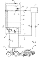
- FIG. 1 shows an OC-LS hydraulic supply system 1 of a tractor 1 a for supplying an external consumer 4 on an implement 4a connected via a Power Beyond system.
- the tractor supply system 1 comprises a fixed displacement pump 2, a fluid reservoir 3, and a valve manifold 10, together with lines 5 , 6, 7 for the connection of the external consumer 4, whereby:
- the pump In an OC-LS hydraulic supply system the pump is constantly delivering fluid flow, whereby the pressure in the supply system depends on the resistance in the supply system. Resistance can be generated by consumers transforming the energy into mechanical work (by lifting a front loader) or even by flow resistance in the components. To keep the losses in the idle mode as low as possible, the discharge of the fluid flow to the tank may suitably occur as close as possible to the pump in order to minimise the effect of resistance in the pipes and keep the system as efficient as possible. On the other hand a certain level of pressure must be maintained to keep the fluid flow active and responsive. This requires compromises in efficiency.
- valve manifold 10 comprises various valve assemblies 20, 30, 40, 50, 60 which can be easily attached together with each valve assembly 20, 30, 40, 50, 60 being shaped like a plate with ports for the hydraulic connection being aligned to the functionally similar port of the adjacent plate.
- the shared ports are named P for the ports connected to pump 2, R for the ports connected to tank 3 and Y for the ports connected to Load sensing signal lines.
- exit ports A, B are for connection with a consumer, e.g. port A may be connected to one side of the piston and port B may be connected to opposing side of the piston of hydraulic lifting cylinder moving the lower links of a three-point-linkage.
- valve manifold 10 can be designed without internal connecting pipes or hoses and is very flexible in terms of the configurations which may be achieved.
- An example of such a manifold is the SB23 Control Block produced by Bosch Rexroth AG of Schwieberdingen, Germany.
- the valve manifold 10 comprises first valve assembly 20 which is directly connected to pump 2 and tank 3 and final valve assembly 40 which closes or redirects ports.
- first valve assembly 20 and final valve assembly 40 intermediate valve assemblies 30, 50, and 60 are provided to control fluid flow to consumers (not shown) on the tractor 1 a (e.g. linkage cylinders) or on the implement 4a (via respective couplings which are not shown).
- the first valve assembly 20 may be designed in that further intermediate valve assemblies can be attached on opposing sides as shown in applicant's published patent application EP 2472162A1 .
- the intermediate valve assemblies 30, 50 and 60 are only indicated with dotted lines.
- the intermediate valve assemblies 30, 50 and 60 can be designed in various configurations depending on the function which has to be controlled.
- valve manifold 10 is shown in detail in Figure 2 whereby valve assemblies 50 and 60 are omitted for better clarity.
- a prioritisation valve 31 and a control valve 32 are provided in position 31 a.
- prioritisation valve 31 solely connects the pump 2 to valve 32 as long as there is demand of valve 32 (forwarded via LS port 31 b). This position is supported by spring 31 c. If the pump 2 supplies more than the demand of valve 32, prioritisation valve 31 is moved towards position 31 d so that part of the fluid flow is directed to the successional intermediate valve assemblies (50, 60 Fig. 1 ). If there is no demand by valve 32, prioritisation valve 31 is moved in position 31 d so that no fluid flows to valve 32.
- valve 32 can differ, for example in the number of ports, proportional valves or two-position valves.
- First valve assembly 20 (shown in more detail in Figure 2 ) is provided to connect valve manifold 10 conjointly to pump 2 via port P and tank 3 via ports R1, R2. Ports R, Y and P are provided for connection with attached intermediate valve assemblies, whereby port R is the return line to tank 3, port P is the pressure line and port Y is the port for the Load Sensing pressure signal LSP.
- Valve assembly 20 comprises:
- Main pressure limiting valve 21 and LS pressure limiting valve 22 open the connection of the respective circuit to tank when pressure level exceeds 210 bar at main pressure limiting valve 21 or 200bar at LS pressure limiting valve 22. Thereby damaging pressure levels are avoided.
- Sequence valve 23 can take closed position 23a (shown) and open position 23b, whereby the fluid flow is blocked in position 23a or ports 23c and 23d are connected in position 23b accordingly.
- Position 23a is biased by spring 23e.
- Pressure charged at control port 23f counteracts the spring 23e which is set to 10 bar in the shown embodiment.
- valve assembly 20 The function of valve assembly 20 is explained below by reference to different operating conditions (Cither) whereby pump 2 is constantly delivering:
- Pump 2 is also charging port 23c of sequence valve 23 but as LSP is charging port 23f against spring 23e and LSP is 7 bar ⁇ 10 bar, sequence valve 23 remains in position 23a.
- valve assemblies 30, 50 or 60 control active consumers.
- sequence valve 23 is moved to position 23b as pressure LSP at control port 23f is higher than the pressure resulting from the force applied by spring 23c. With sequence valve 23 in position 23b, the behaviour of valve assembly 20 is completely changed.
- the major change is in that fluid flow of ⁇ 1 l/min at port Y (for the Load Sensing pressure signal LSP) is provided in the direction from the pump supply to the consumers defined as dynamic pressure signal condition. As explained above, the load sensing signal coming from consumer is adversely affected.
- the valve assembly 20 is installed to provide two different levels of pressure differential, 5 bar and 13.7 bar, whereby the level of 5 bar is needed to ensure operational availability (so that e.g. valves can be adjusted) while the level of 13.7 bar is provided if there is a load sensing signal >10 bar.
- condition C3 characterised by the dynamic LS condition
- a fluid flow coming from pump 2 is entering the LS circuit (port Y) in direction of the intermediate valve assemblies 30, 50, and 60 or especially the Power Beyond system. If any of valve assemblies 30, 50, and 60 is operated, this fluid flow is normally passing these valve assemblies 30, 50, 60 towards the consumer and summed up with a load signal. If the valve assemblies are not operated, the fluid flow is discharged via internal connection to tank (provided in valve assemblies 30, 50, and 60).
- valve assembly 40 comprising:
- the filter element 42 is provided to filter out debris in the fluid entering via external consumer 4 or the fast coupling 7a.
- the amplifier valve 41 is provided in the LS line between the consumer 4 of the Power Beyond system 4 and the port Y connecting valve assembly 40 and valve assemblies 30, 50, and 60 with the first valve assembly 20.
- the amplifier valve 41 has a first port 41 a connected with the LS line coming from external consumer 4.
- a second port 41 b is connected to pump 2 (via valve assemblies 30, 50, and 60 with the first valve assembly 20) and the valve can be adjusted by the driver of the vehicle 1 a to a chosen pressure amplification by means of a solenoid 41 c.
- Third port 41 d is connected with the load sensing signal pressure line Y of the valve manifold 10.
- the amplifier valve 41 is of proportional type so that it can be moved to any position between first position 41 e and second position 41f to adjust the connection of third port 41 d with first port 41 a or/and second port 41 b.
- a spring 41 g plus pressure at port 41 d is biasing position 41 f while the solenoid 41 c is supported by the pressure at port 41 a for pressure control.
- both pressures are superposed to 35 bar which is fed via port 41 d to the valve assembly 20.
- flow control valve 43 limits the fluid flow to 0,5 l/min so that trapped fluid can be discharged but the load sensing signal pressure is not falsified too much when an external consumer 4 is connected.
- a further flow control valve 44 (set to a limitation of 0.9 l/min) and a connection to tank line R is provided.
- the fluid flow of ⁇ 1 l/min coming from valve assembly 20 (as to dynamic load sensing signal condition) . can be discharged at least partly to tank via flow control valve 44.
- the setting of 0.9 l/min for flow control valve 44 is chosen for the shown embodiment as the fluid flow in dynamic LS condition varies between 0.2 l/min and 0.9 l/min.
- flow control valve 43 could additionally discharge a remaining fluid flow (up to 0.5 l/min).
- the setting for valve 44 regarding the limitation of the fluid flow can be adapted to the conditions of the supply system.
- the flow control valve 44 does not falsify the load sensing pressure signal coming via Power Beyond as amplifier valve 41 permanently adjusts amplification and compensates fluid discharged via flow control valve 44.
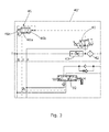
- FIG. 3 shows an alternative embodiment with final valve assembly 40' wherein the flow control valve 44 is replaced by a pressure compensator 46.
- the pressure compensator is provided to discharge the fluid flow coming from valve assembly 20 if there is no load sensing signal (demand) coming from the consumer of the Power Beyond system via amplifier valve 41.
- Pressure compensator 46 can take every position in between Position 46a and 46b .Position 46a is biased with spring 46c (set to 3 bar) resulting in the consumers load sensing signal being reduced by 3 bar which may be compensated by higher amplification.
Landscapes
- Engineering & Computer Science (AREA)
- Physics & Mathematics (AREA)
- Fluid Mechanics (AREA)
- Mechanical Engineering (AREA)
- General Engineering & Computer Science (AREA)
- Fluid-Pressure Circuits (AREA)
Applications Claiming Priority (1)
| Application Number | Priority Date | Filing Date | Title |
|---|---|---|---|
| GB201319116A GB201319116D0 (en) | 2013-10-30 | 2013-10-30 | Hydraulic pressure supply system |
Publications (2)
| Publication Number | Publication Date |
|---|---|
| EP2878829A1 true EP2878829A1 (de) | 2015-06-03 |
| EP2878829B1 EP2878829B1 (de) | 2018-04-25 |
Family
ID=49767345
Family Applications (1)
| Application Number | Title | Priority Date | Filing Date |
|---|---|---|---|
| EP14187163.2A Active EP2878829B1 (de) | 2013-10-30 | 2014-09-30 | Hydraulisches Druckversorgungssystem |
Country Status (2)
| Country | Link |
|---|---|
| EP (1) | EP2878829B1 (de) |
| GB (1) | GB201319116D0 (de) |
Cited By (4)
| Publication number | Priority date | Publication date | Assignee | Title |
|---|---|---|---|---|
| SE2150253A1 (en) * | 2021-03-04 | 2022-09-05 | Husqvarna Ab | An energy efficient hydraulic system for construction machines |
| US12173732B2 (en) | 2021-12-03 | 2024-12-24 | Agco International Gmbh | System and method for controlling a hydraulic supply system on a mobile machine |
| US12188497B2 (en) | 2021-12-03 | 2025-01-07 | Agco International Gmbh | System and method for controlling a hydraulic supply system on a mobile machine |
| US12529388B2 (en) | 2021-12-03 | 2026-01-20 | Agco International Gmbh | Mobile machine and method |
Citations (3)
| Publication number | Priority date | Publication date | Assignee | Title |
|---|---|---|---|---|
| WO2005093263A1 (de) * | 2004-03-09 | 2005-10-06 | Bucher Hydraulics Gmbh | Hydraulisches steuersystem |
| EP1783378A2 (de) * | 2005-11-08 | 2007-05-09 | AGCO GmbH | Hydraulisches System mit Lastdruckerkennung für landwirtschaftliche Traktoren |
| EP1843047A2 (de) * | 2006-04-07 | 2007-10-10 | AGCO GmbH | Hydraulische Zuführungssysteme |
-
2013
- 2013-10-30 GB GB201319116A patent/GB201319116D0/en not_active Ceased
-
2014
- 2014-09-30 EP EP14187163.2A patent/EP2878829B1/de active Active
Patent Citations (3)
| Publication number | Priority date | Publication date | Assignee | Title |
|---|---|---|---|---|
| WO2005093263A1 (de) * | 2004-03-09 | 2005-10-06 | Bucher Hydraulics Gmbh | Hydraulisches steuersystem |
| EP1783378A2 (de) * | 2005-11-08 | 2007-05-09 | AGCO GmbH | Hydraulisches System mit Lastdruckerkennung für landwirtschaftliche Traktoren |
| EP1843047A2 (de) * | 2006-04-07 | 2007-10-10 | AGCO GmbH | Hydraulische Zuführungssysteme |
Cited By (6)
| Publication number | Priority date | Publication date | Assignee | Title |
|---|---|---|---|---|
| SE2150253A1 (en) * | 2021-03-04 | 2022-09-05 | Husqvarna Ab | An energy efficient hydraulic system for construction machines |
| WO2022186752A1 (en) * | 2021-03-04 | 2022-09-09 | Husqvarna Ab | An energy efficient hydraulic system for construction machines |
| SE545533C2 (en) * | 2021-03-04 | 2023-10-17 | Husqvarna Ab | A hydraulic system for construction machines and a method for controlling the hydraulic system |
| US12173732B2 (en) | 2021-12-03 | 2024-12-24 | Agco International Gmbh | System and method for controlling a hydraulic supply system on a mobile machine |
| US12188497B2 (en) | 2021-12-03 | 2025-01-07 | Agco International Gmbh | System and method for controlling a hydraulic supply system on a mobile machine |
| US12529388B2 (en) | 2021-12-03 | 2026-01-20 | Agco International Gmbh | Mobile machine and method |
Also Published As
| Publication number | Publication date |
|---|---|
| EP2878829B1 (de) | 2018-04-25 |
| GB201319116D0 (en) | 2013-12-11 |
Similar Documents
| Publication | Publication Date | Title |
|---|---|---|
| US11572670B2 (en) | Hydraulic control arrangement for an arrangement of mobile machines, and arrangement of mobile machines | |
| US8925439B2 (en) | Valve control valve circuit for operating a single acting hydraulic cylinder | |
| EP2878829B1 (de) | Hydraulisches Druckversorgungssystem | |
| US20100078185A1 (en) | Active implement down force system providing reduced heat generation | |
| US6502500B2 (en) | Hydraulic system for a work machine | |
| EP2884118A1 (de) | Hydraulisches Versorgungssystem | |
| US20110120297A1 (en) | Hydraulic Circuit | |
| EP1760325B1 (de) | Hydraulisches Load-Sensing-System für Traktoren | |
| US8347617B2 (en) | Hydralic two-circuit system and interconnecting valve system | |
| EP1843047B1 (de) | Hydraulische Zuführungssysteme | |
| US7870728B2 (en) | Hydraulic control arrangement | |
| CN211448991U (zh) | 控制设备 | |
| US9404483B2 (en) | Hydraulic control arrangement | |
| US7395664B2 (en) | Hydraulic system for utility vehicles, in particular agricultural tractors | |
| DE102011107218A1 (de) | Hydrostatisches Antriebssystem | |
| EP1070852B1 (de) | Hydraulisches System einer Arbeitsmaschine | |
| EP2256082B9 (de) | Hydrostatisches Antriebssystem einer mobilen Arbeitsmaschine | |
| US9003786B2 (en) | Pressure limiting in hydraulic systems | |
| DE102011107222A1 (de) | Hydrostatisches Antriebssystem mit einer im Fördervolumen verstellbaren Pumpe | |
| EP3002462B1 (de) | Hydraulisches steuersystem | |
| DE102010048890A1 (de) | Hydrostatisches Antriebssystem | |
| DE102016107526A1 (de) | Verstärkerventil für eine als Closed-Center-System ausgebildete Arbeitshydraulik einer land- oder bauwirtschaftlich nutzbaren Arbeitsmaschine | |
| EP2980006B1 (de) | Hydraulikanlage einer mobilen arbeitsmaschine, insbesondere eines flurförderzeugs | |
| WO2023100005A1 (en) | System and method for controlling a hydraulic supply system on a mobile machine | |
| IT202300017646A1 (it) | Architettura idraulica migliorata per un veicolo da lavoro, relativo metodo di controllo, e veicolo da lavoro comprendente tale architettura idraulica |
Legal Events
| Date | Code | Title | Description |
|---|---|---|---|
| PUAI | Public reference made under article 153(3) epc to a published international application that has entered the european phase |
Free format text: ORIGINAL CODE: 0009012 |
|
| 17P | Request for examination filed |
Effective date: 20140930 |
|
| AK | Designated contracting states |
Kind code of ref document: A1 Designated state(s): AL AT BE BG CH CY CZ DE DK EE ES FI FR GB GR HR HU IE IS IT LI LT LU LV MC MK MT NL NO PL PT RO RS SE SI SK SM TR |
|
| AX | Request for extension of the european patent |
Extension state: BA ME |
|
| R17P | Request for examination filed (corrected) |
Effective date: 20151203 |
|
| RBV | Designated contracting states (corrected) |
Designated state(s): AL AT BE BG CH CY CZ DE DK EE ES FI FR GB GR HR HU IE IS IT LI LT LU LV MC MK MT NL NO PL PT RO RS SE SI SK SM TR |
|
| GRAP | Despatch of communication of intention to grant a patent |
Free format text: ORIGINAL CODE: EPIDOSNIGR1 |
|
| STAA | Information on the status of an ep patent application or granted ep patent |
Free format text: STATUS: GRANT OF PATENT IS INTENDED |
|
| INTG | Intention to grant announced |
Effective date: 20171221 |
|
| GRAA | (expected) grant |
Free format text: ORIGINAL CODE: 0009210 |
|
| GRAS | Grant fee paid |
Free format text: ORIGINAL CODE: EPIDOSNIGR3 |
|
| STAA | Information on the status of an ep patent application or granted ep patent |
Free format text: STATUS: THE PATENT HAS BEEN GRANTED |
|
| AK | Designated contracting states |
Kind code of ref document: B1 Designated state(s): AL AT BE BG CH CY CZ DE DK EE ES FI FR GB GR HR HU IE IS IT LI LT LU LV MC MK MT NL NO PL PT RO RS SE SI SK SM TR |
|
| REG | Reference to a national code |
Ref country code: GB Ref legal event code: FG4D |
|
| REG | Reference to a national code |
Ref country code: CH Ref legal event code: EP |
|
| REG | Reference to a national code |
Ref country code: AT Ref legal event code: REF Ref document number: 993222 Country of ref document: AT Kind code of ref document: T Effective date: 20180515 |
|
| REG | Reference to a national code |
Ref country code: IE Ref legal event code: FG4D |
|
| REG | Reference to a national code |
Ref country code: DE Ref legal event code: R096 Ref document number: 602014024336 Country of ref document: DE |
|
| REG | Reference to a national code |
Ref country code: NL Ref legal event code: MP Effective date: 20180425 |
|
| REG | Reference to a national code |
Ref country code: LT Ref legal event code: MG4D |
|
| REG | Reference to a national code |
Ref country code: FR Ref legal event code: PLFP Year of fee payment: 5 |
|
| PG25 | Lapsed in a contracting state [announced via postgrant information from national office to epo] |
Ref country code: NL Free format text: LAPSE BECAUSE OF FAILURE TO SUBMIT A TRANSLATION OF THE DESCRIPTION OR TO PAY THE FEE WITHIN THE PRESCRIBED TIME-LIMIT Effective date: 20180425 |
|
| PG25 | Lapsed in a contracting state [announced via postgrant information from national office to epo] |
Ref country code: BG Free format text: LAPSE BECAUSE OF FAILURE TO SUBMIT A TRANSLATION OF THE DESCRIPTION OR TO PAY THE FEE WITHIN THE PRESCRIBED TIME-LIMIT Effective date: 20180725 Ref country code: NO Free format text: LAPSE BECAUSE OF FAILURE TO SUBMIT A TRANSLATION OF THE DESCRIPTION OR TO PAY THE FEE WITHIN THE PRESCRIBED TIME-LIMIT Effective date: 20180725 Ref country code: FI Free format text: LAPSE BECAUSE OF FAILURE TO SUBMIT A TRANSLATION OF THE DESCRIPTION OR TO PAY THE FEE WITHIN THE PRESCRIBED TIME-LIMIT Effective date: 20180425 Ref country code: SE Free format text: LAPSE BECAUSE OF FAILURE TO SUBMIT A TRANSLATION OF THE DESCRIPTION OR TO PAY THE FEE WITHIN THE PRESCRIBED TIME-LIMIT Effective date: 20180425 Ref country code: PL Free format text: LAPSE BECAUSE OF FAILURE TO SUBMIT A TRANSLATION OF THE DESCRIPTION OR TO PAY THE FEE WITHIN THE PRESCRIBED TIME-LIMIT Effective date: 20180425 Ref country code: LT Free format text: LAPSE BECAUSE OF FAILURE TO SUBMIT A TRANSLATION OF THE DESCRIPTION OR TO PAY THE FEE WITHIN THE PRESCRIBED TIME-LIMIT Effective date: 20180425 Ref country code: ES Free format text: LAPSE BECAUSE OF FAILURE TO SUBMIT A TRANSLATION OF THE DESCRIPTION OR TO PAY THE FEE WITHIN THE PRESCRIBED TIME-LIMIT Effective date: 20180425 |
|
| PG25 | Lapsed in a contracting state [announced via postgrant information from national office to epo] |
Ref country code: RS Free format text: LAPSE BECAUSE OF FAILURE TO SUBMIT A TRANSLATION OF THE DESCRIPTION OR TO PAY THE FEE WITHIN THE PRESCRIBED TIME-LIMIT Effective date: 20180425 Ref country code: LV Free format text: LAPSE BECAUSE OF FAILURE TO SUBMIT A TRANSLATION OF THE DESCRIPTION OR TO PAY THE FEE WITHIN THE PRESCRIBED TIME-LIMIT Effective date: 20180425 Ref country code: HR Free format text: LAPSE BECAUSE OF FAILURE TO SUBMIT A TRANSLATION OF THE DESCRIPTION OR TO PAY THE FEE WITHIN THE PRESCRIBED TIME-LIMIT Effective date: 20180425 Ref country code: GR Free format text: LAPSE BECAUSE OF FAILURE TO SUBMIT A TRANSLATION OF THE DESCRIPTION OR TO PAY THE FEE WITHIN THE PRESCRIBED TIME-LIMIT Effective date: 20180726 |
|
| REG | Reference to a national code |
Ref country code: AT Ref legal event code: MK05 Ref document number: 993222 Country of ref document: AT Kind code of ref document: T Effective date: 20180425 |
|
| PG25 | Lapsed in a contracting state [announced via postgrant information from national office to epo] |
Ref country code: PT Free format text: LAPSE BECAUSE OF FAILURE TO SUBMIT A TRANSLATION OF THE DESCRIPTION OR TO PAY THE FEE WITHIN THE PRESCRIBED TIME-LIMIT Effective date: 20180827 |
|
| REG | Reference to a national code |
Ref country code: DE Ref legal event code: R097 Ref document number: 602014024336 Country of ref document: DE |
|
| PG25 | Lapsed in a contracting state [announced via postgrant information from national office to epo] |
Ref country code: RO Free format text: LAPSE BECAUSE OF FAILURE TO SUBMIT A TRANSLATION OF THE DESCRIPTION OR TO PAY THE FEE WITHIN THE PRESCRIBED TIME-LIMIT Effective date: 20180425 Ref country code: DK Free format text: LAPSE BECAUSE OF FAILURE TO SUBMIT A TRANSLATION OF THE DESCRIPTION OR TO PAY THE FEE WITHIN THE PRESCRIBED TIME-LIMIT Effective date: 20180425 Ref country code: EE Free format text: LAPSE BECAUSE OF FAILURE TO SUBMIT A TRANSLATION OF THE DESCRIPTION OR TO PAY THE FEE WITHIN THE PRESCRIBED TIME-LIMIT Effective date: 20180425 Ref country code: AT Free format text: LAPSE BECAUSE OF FAILURE TO SUBMIT A TRANSLATION OF THE DESCRIPTION OR TO PAY THE FEE WITHIN THE PRESCRIBED TIME-LIMIT Effective date: 20180425 Ref country code: CZ Free format text: LAPSE BECAUSE OF FAILURE TO SUBMIT A TRANSLATION OF THE DESCRIPTION OR TO PAY THE FEE WITHIN THE PRESCRIBED TIME-LIMIT Effective date: 20180425 Ref country code: SK Free format text: LAPSE BECAUSE OF FAILURE TO SUBMIT A TRANSLATION OF THE DESCRIPTION OR TO PAY THE FEE WITHIN THE PRESCRIBED TIME-LIMIT Effective date: 20180425 |
|
| PG25 | Lapsed in a contracting state [announced via postgrant information from national office to epo] |
Ref country code: SM Free format text: LAPSE BECAUSE OF FAILURE TO SUBMIT A TRANSLATION OF THE DESCRIPTION OR TO PAY THE FEE WITHIN THE PRESCRIBED TIME-LIMIT Effective date: 20180425 Ref country code: IT Free format text: LAPSE BECAUSE OF FAILURE TO SUBMIT A TRANSLATION OF THE DESCRIPTION OR TO PAY THE FEE WITHIN THE PRESCRIBED TIME-LIMIT Effective date: 20180425 |
|
| PLBE | No opposition filed within time limit |
Free format text: ORIGINAL CODE: 0009261 |
|
| STAA | Information on the status of an ep patent application or granted ep patent |
Free format text: STATUS: NO OPPOSITION FILED WITHIN TIME LIMIT |
|
| 26N | No opposition filed |
Effective date: 20190128 |
|
| PG25 | Lapsed in a contracting state [announced via postgrant information from national office to epo] |
Ref country code: MC Free format text: LAPSE BECAUSE OF FAILURE TO SUBMIT A TRANSLATION OF THE DESCRIPTION OR TO PAY THE FEE WITHIN THE PRESCRIBED TIME-LIMIT Effective date: 20180425 |
|
| REG | Reference to a national code |
Ref country code: CH Ref legal event code: PL |
|
| GBPC | Gb: european patent ceased through non-payment of renewal fee |
Effective date: 20180930 |
|
| PG25 | Lapsed in a contracting state [announced via postgrant information from national office to epo] |
Ref country code: SI Free format text: LAPSE BECAUSE OF FAILURE TO SUBMIT A TRANSLATION OF THE DESCRIPTION OR TO PAY THE FEE WITHIN THE PRESCRIBED TIME-LIMIT Effective date: 20180425 |
|
| REG | Reference to a national code |
Ref country code: BE Ref legal event code: MM Effective date: 20180930 |
|
| REG | Reference to a national code |
Ref country code: IE Ref legal event code: MM4A |
|
| PG25 | Lapsed in a contracting state [announced via postgrant information from national office to epo] |
Ref country code: LU Free format text: LAPSE BECAUSE OF NON-PAYMENT OF DUE FEES Effective date: 20180930 |
|
| PG25 | Lapsed in a contracting state [announced via postgrant information from national office to epo] |
Ref country code: IE Free format text: LAPSE BECAUSE OF NON-PAYMENT OF DUE FEES Effective date: 20180930 |
|
| PG25 | Lapsed in a contracting state [announced via postgrant information from national office to epo] |
Ref country code: CH Free format text: LAPSE BECAUSE OF NON-PAYMENT OF DUE FEES Effective date: 20180930 Ref country code: BE Free format text: LAPSE BECAUSE OF NON-PAYMENT OF DUE FEES Effective date: 20180930 Ref country code: LI Free format text: LAPSE BECAUSE OF NON-PAYMENT OF DUE FEES Effective date: 20180930 |
|
| PG25 | Lapsed in a contracting state [announced via postgrant information from national office to epo] |
Ref country code: GB Free format text: LAPSE BECAUSE OF NON-PAYMENT OF DUE FEES Effective date: 20180930 |
|
| PG25 | Lapsed in a contracting state [announced via postgrant information from national office to epo] |
Ref country code: AL Free format text: LAPSE BECAUSE OF FAILURE TO SUBMIT A TRANSLATION OF THE DESCRIPTION OR TO PAY THE FEE WITHIN THE PRESCRIBED TIME-LIMIT Effective date: 20180425 |
|
| PG25 | Lapsed in a contracting state [announced via postgrant information from national office to epo] |
Ref country code: MT Free format text: LAPSE BECAUSE OF NON-PAYMENT OF DUE FEES Effective date: 20180930 |
|
| PG25 | Lapsed in a contracting state [announced via postgrant information from national office to epo] |
Ref country code: TR Free format text: LAPSE BECAUSE OF FAILURE TO SUBMIT A TRANSLATION OF THE DESCRIPTION OR TO PAY THE FEE WITHIN THE PRESCRIBED TIME-LIMIT Effective date: 20180425 |
|
| PG25 | Lapsed in a contracting state [announced via postgrant information from national office to epo] |
Ref country code: HU Free format text: LAPSE BECAUSE OF FAILURE TO SUBMIT A TRANSLATION OF THE DESCRIPTION OR TO PAY THE FEE WITHIN THE PRESCRIBED TIME-LIMIT; INVALID AB INITIO Effective date: 20140930 |
|
| PG25 | Lapsed in a contracting state [announced via postgrant information from national office to epo] |
Ref country code: CY Free format text: LAPSE BECAUSE OF FAILURE TO SUBMIT A TRANSLATION OF THE DESCRIPTION OR TO PAY THE FEE WITHIN THE PRESCRIBED TIME-LIMIT Effective date: 20180425 Ref country code: MK Free format text: LAPSE BECAUSE OF NON-PAYMENT OF DUE FEES Effective date: 20180425 |
|
| PG25 | Lapsed in a contracting state [announced via postgrant information from national office to epo] |
Ref country code: IS Free format text: LAPSE BECAUSE OF FAILURE TO SUBMIT A TRANSLATION OF THE DESCRIPTION OR TO PAY THE FEE WITHIN THE PRESCRIBED TIME-LIMIT Effective date: 20180825 |
|
| REG | Reference to a national code |
Ref country code: DE Ref legal event code: R084 Ref document number: 602014024336 Country of ref document: DE |
|
| P01 | Opt-out of the competence of the unified patent court (upc) registered |
Effective date: 20230518 |
|
| PGFP | Annual fee paid to national office [announced via postgrant information from national office to epo] |
Ref country code: DE Payment date: 20250919 Year of fee payment: 12 |
|
| PGFP | Annual fee paid to national office [announced via postgrant information from national office to epo] |
Ref country code: FR Payment date: 20250922 Year of fee payment: 12 |