EP2878856A1 - Engrenage et procédé pour le faire fonctionner - Google Patents
Engrenage et procédé pour le faire fonctionner Download PDFInfo
- Publication number
- EP2878856A1 EP2878856A1 EP13195138.6A EP13195138A EP2878856A1 EP 2878856 A1 EP2878856 A1 EP 2878856A1 EP 13195138 A EP13195138 A EP 13195138A EP 2878856 A1 EP2878856 A1 EP 2878856A1
- Authority
- EP
- European Patent Office
- Prior art keywords
- transmission
- gear
- partial
- output shaft
- input shaft
- Prior art date
- Legal status (The legal status is an assumption and is not a legal conclusion. Google has not performed a legal analysis and makes no representation as to the accuracy of the status listed.)
- Withdrawn
Links
- 238000011017 operating method Methods 0.000 title 1
- 230000005540 biological transmission Effects 0.000 claims abstract description 418
- 238000000034 method Methods 0.000 claims description 9
- 230000008878 coupling Effects 0.000 description 7
- 238000010168 coupling process Methods 0.000 description 7
- 238000005859 coupling reaction Methods 0.000 description 7
- 238000010586 diagram Methods 0.000 description 6
- 238000013461 design Methods 0.000 description 5
- 238000013519 translation Methods 0.000 description 4
- 230000014616 translation Effects 0.000 description 4
- 238000013459 approach Methods 0.000 description 3
- 238000010276 construction Methods 0.000 description 2
- 239000000446 fuel Substances 0.000 description 2
- 230000007935 neutral effect Effects 0.000 description 2
- 230000001133 acceleration Effects 0.000 description 1
- 238000002485 combustion reaction Methods 0.000 description 1
- 238000004891 communication Methods 0.000 description 1
- 238000011161 development Methods 0.000 description 1
- 230000009977 dual effect Effects 0.000 description 1
- 230000008030 elimination Effects 0.000 description 1
- 238000003379 elimination reaction Methods 0.000 description 1
- 238000005461 lubrication Methods 0.000 description 1
- 238000004519 manufacturing process Methods 0.000 description 1
- 238000002360 preparation method Methods 0.000 description 1
- 238000003825 pressing Methods 0.000 description 1
- 230000000284 resting effect Effects 0.000 description 1
Images




Classifications
-
- F—MECHANICAL ENGINEERING; LIGHTING; HEATING; WEAPONS; BLASTING
- F16—ENGINEERING ELEMENTS AND UNITS; GENERAL MEASURES FOR PRODUCING AND MAINTAINING EFFECTIVE FUNCTIONING OF MACHINES OR INSTALLATIONS; THERMAL INSULATION IN GENERAL
- F16H—GEARING
- F16H3/00—Toothed gearings for conveying rotary motion with variable gear ratio or for reversing rotary motion
- F16H3/02—Toothed gearings for conveying rotary motion with variable gear ratio or for reversing rotary motion without gears having orbital motion
- F16H3/08—Toothed gearings for conveying rotary motion with variable gear ratio or for reversing rotary motion without gears having orbital motion exclusively or essentially with continuously meshing gears, that can be disengaged from their shafts
- F16H3/087—Toothed gearings for conveying rotary motion with variable gear ratio or for reversing rotary motion without gears having orbital motion exclusively or essentially with continuously meshing gears, that can be disengaged from their shafts characterised by the disposition of the gears
- F16H3/093—Toothed gearings for conveying rotary motion with variable gear ratio or for reversing rotary motion without gears having orbital motion exclusively or essentially with continuously meshing gears, that can be disengaged from their shafts characterised by the disposition of the gears with two or more countershafts
-
- F—MECHANICAL ENGINEERING; LIGHTING; HEATING; WEAPONS; BLASTING
- F16—ENGINEERING ELEMENTS AND UNITS; GENERAL MEASURES FOR PRODUCING AND MAINTAINING EFFECTIVE FUNCTIONING OF MACHINES OR INSTALLATIONS; THERMAL INSULATION IN GENERAL
- F16H—GEARING
- F16H3/00—Toothed gearings for conveying rotary motion with variable gear ratio or for reversing rotary motion
- F16H3/006—Toothed gearings for conveying rotary motion with variable gear ratio or for reversing rotary motion power being selectively transmitted by parallel flow paths, e.g. dual clutch transmissions
-
- F—MECHANICAL ENGINEERING; LIGHTING; HEATING; WEAPONS; BLASTING
- F16—ENGINEERING ELEMENTS AND UNITS; GENERAL MEASURES FOR PRODUCING AND MAINTAINING EFFECTIVE FUNCTIONING OF MACHINES OR INSTALLATIONS; THERMAL INSULATION IN GENERAL
- F16H—GEARING
- F16H3/00—Toothed gearings for conveying rotary motion with variable gear ratio or for reversing rotary motion
- F16H3/02—Toothed gearings for conveying rotary motion with variable gear ratio or for reversing rotary motion without gears having orbital motion
- F16H3/08—Toothed gearings for conveying rotary motion with variable gear ratio or for reversing rotary motion without gears having orbital motion exclusively or essentially with continuously meshing gears, that can be disengaged from their shafts
- F16H3/087—Toothed gearings for conveying rotary motion with variable gear ratio or for reversing rotary motion without gears having orbital motion exclusively or essentially with continuously meshing gears, that can be disengaged from their shafts characterised by the disposition of the gears
- F16H3/091—Toothed gearings for conveying rotary motion with variable gear ratio or for reversing rotary motion without gears having orbital motion exclusively or essentially with continuously meshing gears, that can be disengaged from their shafts characterised by the disposition of the gears including a single countershaft
- F16H3/0915—Toothed gearings for conveying rotary motion with variable gear ratio or for reversing rotary motion without gears having orbital motion exclusively or essentially with continuously meshing gears, that can be disengaged from their shafts characterised by the disposition of the gears including a single countershaft with coaxial input and output shafts
-
- F—MECHANICAL ENGINEERING; LIGHTING; HEATING; WEAPONS; BLASTING
- F16—ENGINEERING ELEMENTS AND UNITS; GENERAL MEASURES FOR PRODUCING AND MAINTAINING EFFECTIVE FUNCTIONING OF MACHINES OR INSTALLATIONS; THERMAL INSULATION IN GENERAL
- F16H—GEARING
- F16H3/00—Toothed gearings for conveying rotary motion with variable gear ratio or for reversing rotary motion
- F16H3/02—Toothed gearings for conveying rotary motion with variable gear ratio or for reversing rotary motion without gears having orbital motion
- F16H3/08—Toothed gearings for conveying rotary motion with variable gear ratio or for reversing rotary motion without gears having orbital motion exclusively or essentially with continuously meshing gears, that can be disengaged from their shafts
- F16H3/087—Toothed gearings for conveying rotary motion with variable gear ratio or for reversing rotary motion without gears having orbital motion exclusively or essentially with continuously meshing gears, that can be disengaged from their shafts characterised by the disposition of the gears
- F16H3/093—Toothed gearings for conveying rotary motion with variable gear ratio or for reversing rotary motion without gears having orbital motion exclusively or essentially with continuously meshing gears, that can be disengaged from their shafts characterised by the disposition of the gears with two or more countershafts
- F16H3/097—Toothed gearings for conveying rotary motion with variable gear ratio or for reversing rotary motion without gears having orbital motion exclusively or essentially with continuously meshing gears, that can be disengaged from their shafts characterised by the disposition of the gears with two or more countershafts the input and output shafts being aligned on the same axis
-
- F—MECHANICAL ENGINEERING; LIGHTING; HEATING; WEAPONS; BLASTING
- F16—ENGINEERING ELEMENTS AND UNITS; GENERAL MEASURES FOR PRODUCING AND MAINTAINING EFFECTIVE FUNCTIONING OF MACHINES OR INSTALLATIONS; THERMAL INSULATION IN GENERAL
- F16D—COUPLINGS FOR TRANSMITTING ROTATION; CLUTCHES; BRAKES
- F16D11/00—Clutches in which the members have interengaging parts
-
- F—MECHANICAL ENGINEERING; LIGHTING; HEATING; WEAPONS; BLASTING
- F16—ENGINEERING ELEMENTS AND UNITS; GENERAL MEASURES FOR PRODUCING AND MAINTAINING EFFECTIVE FUNCTIONING OF MACHINES OR INSTALLATIONS; THERMAL INSULATION IN GENERAL
- F16D—COUPLINGS FOR TRANSMITTING ROTATION; CLUTCHES; BRAKES
- F16D11/00—Clutches in which the members have interengaging parts
- F16D11/14—Clutches in which the members have interengaging parts with clutching members movable only axially
-
- F—MECHANICAL ENGINEERING; LIGHTING; HEATING; WEAPONS; BLASTING
- F16—ENGINEERING ELEMENTS AND UNITS; GENERAL MEASURES FOR PRODUCING AND MAINTAINING EFFECTIVE FUNCTIONING OF MACHINES OR INSTALLATIONS; THERMAL INSULATION IN GENERAL
- F16D—COUPLINGS FOR TRANSMITTING ROTATION; CLUTCHES; BRAKES
- F16D13/00—Friction clutches
-
- F—MECHANICAL ENGINEERING; LIGHTING; HEATING; WEAPONS; BLASTING
- F16—ENGINEERING ELEMENTS AND UNITS; GENERAL MEASURES FOR PRODUCING AND MAINTAINING EFFECTIVE FUNCTIONING OF MACHINES OR INSTALLATIONS; THERMAL INSULATION IN GENERAL
- F16D—COUPLINGS FOR TRANSMITTING ROTATION; CLUTCHES; BRAKES
- F16D11/00—Clutches in which the members have interengaging parts
- F16D2011/008—Clutches in which the members have interengaging parts characterised by the form of the teeth forming the inter-engaging parts; Details of shape or structure of these teeth
-
- F—MECHANICAL ENGINEERING; LIGHTING; HEATING; WEAPONS; BLASTING
- F16—ENGINEERING ELEMENTS AND UNITS; GENERAL MEASURES FOR PRODUCING AND MAINTAINING EFFECTIVE FUNCTIONING OF MACHINES OR INSTALLATIONS; THERMAL INSULATION IN GENERAL
- F16D—COUPLINGS FOR TRANSMITTING ROTATION; CLUTCHES; BRAKES
- F16D2500/00—External control of clutches by electric or electronic means
- F16D2500/10—System to be controlled
- F16D2500/104—Clutch
- F16D2500/10443—Clutch type
- F16D2500/10462—Dog-type clutch
-
- F—MECHANICAL ENGINEERING; LIGHTING; HEATING; WEAPONS; BLASTING
- F16—ENGINEERING ELEMENTS AND UNITS; GENERAL MEASURES FOR PRODUCING AND MAINTAINING EFFECTIVE FUNCTIONING OF MACHINES OR INSTALLATIONS; THERMAL INSULATION IN GENERAL
- F16H—GEARING
- F16H3/00—Toothed gearings for conveying rotary motion with variable gear ratio or for reversing rotary motion
- F16H3/006—Toothed gearings for conveying rotary motion with variable gear ratio or for reversing rotary motion power being selectively transmitted by parallel flow paths, e.g. dual clutch transmissions
- F16H2003/007—Toothed gearings for conveying rotary motion with variable gear ratio or for reversing rotary motion power being selectively transmitted by parallel flow paths, e.g. dual clutch transmissions with two flow paths, one being directly connected to the input, the other being connected to the input through a clutch
-
- F—MECHANICAL ENGINEERING; LIGHTING; HEATING; WEAPONS; BLASTING
- F16—ENGINEERING ELEMENTS AND UNITS; GENERAL MEASURES FOR PRODUCING AND MAINTAINING EFFECTIVE FUNCTIONING OF MACHINES OR INSTALLATIONS; THERMAL INSULATION IN GENERAL
- F16H—GEARING
- F16H3/00—Toothed gearings for conveying rotary motion with variable gear ratio or for reversing rotary motion
- F16H3/02—Toothed gearings for conveying rotary motion with variable gear ratio or for reversing rotary motion without gears having orbital motion
- F16H3/08—Toothed gearings for conveying rotary motion with variable gear ratio or for reversing rotary motion without gears having orbital motion exclusively or essentially with continuously meshing gears, that can be disengaged from their shafts
- F16H2003/0818—Toothed gearings for conveying rotary motion with variable gear ratio or for reversing rotary motion without gears having orbital motion exclusively or essentially with continuously meshing gears, that can be disengaged from their shafts comprising means for power-shifting
-
- F—MECHANICAL ENGINEERING; LIGHTING; HEATING; WEAPONS; BLASTING
- F16—ENGINEERING ELEMENTS AND UNITS; GENERAL MEASURES FOR PRODUCING AND MAINTAINING EFFECTIVE FUNCTIONING OF MACHINES OR INSTALLATIONS; THERMAL INSULATION IN GENERAL
- F16H—GEARING
- F16H2200/00—Transmissions for multiple ratios
- F16H2200/003—Transmissions for multiple ratios characterised by the number of forward speeds
- F16H2200/0052—Transmissions for multiple ratios characterised by the number of forward speeds the gear ratios comprising six forward speeds
-
- F—MECHANICAL ENGINEERING; LIGHTING; HEATING; WEAPONS; BLASTING
- F16—ENGINEERING ELEMENTS AND UNITS; GENERAL MEASURES FOR PRODUCING AND MAINTAINING EFFECTIVE FUNCTIONING OF MACHINES OR INSTALLATIONS; THERMAL INSULATION IN GENERAL
- F16H—GEARING
- F16H2200/00—Transmissions for multiple ratios
- F16H2200/003—Transmissions for multiple ratios characterised by the number of forward speeds
- F16H2200/0056—Transmissions for multiple ratios characterised by the number of forward speeds the gear ratios comprising seven forward speeds
Definitions
- the invention relates to a transmission with at least two partial transmissions, which have respective partial transmission shafts and are independently switchable, and a method for operating such a transmission.
- dual-clutch transmissions have various disadvantages, in the first place, the high design complexity is mentioned. Due to the fact that during normal driving with engaged gears in both partial transmissions always one clutch open and the other clutch must be kept closed, hydraulic pumps with a very high flow rate for actuation and lubrication are needed, which in addition to the design effort and the efficiency of a such dual-clutch transmission equipped vehicles, since the constant volume flow causes additional fuel consumption.
- dual-clutch transmissions still do not achieve the switching performance of converter transmissions in various areas. For example, can be switched by the division of the transmission in two partial transmissions of the fourth switching stage only in the third or fifth switching stage, but not in the second switching stage, which for example when approaching Intersections can lead to problems when it would be necessary to downshift two switching stages in order to achieve the desired acceleration.
- one of the at least two transmission input shafts bypasses the friction clutch and is connected directly to the engine output shaft.
- a friction clutch is required and it can be dispensed with in comparison to the known dual clutch transmissions on a friction clutch.
- the individual gear stages of at least the second partial transmission can be actuated by means of respective shift elements.
- the switching elements which are directly connected to the motor output shaft are designed as positive, force-actuated switching elements which are deactivated when the actuating force is removed, it is ensured that the switching elements are deactivated as soon as the actuating force is removed so that the corresponding gear stage is taken out automatically or is solved. This reliably prevents two different gear ratios are engaged in the two partial transmissions and are connected to the engine output shaft and the transmission output shaft, which would otherwise lead to significant damage to the transmission.
- the second transmission input shaft can be brought into operative connection with the at least two partial transmission shafts via respective transmission means and switching elements operatively connected thereto.
- the transmission means and standing with the same operatively connected switching elements can be connected to the motor output shaft directly connected, second transmission input shaft to the desired sub-transmission in a very simple manner, in turn, the switching elements can be made relatively simple and therefore cost.
- the standing with the transmission means in operative connection switching elements are designed as positive, power-operated switching elements, which are deactivated when the operating force ceases. As explained above, this ensures that the switching elements are deactivated as soon as the actuating force is removed, thereby automatically removing the engaged gear stage.
- the transmission means are designed as gear pairs.
- Gearwheels are components that have been introduced in gearbox construction and work extremely reliably.
- a structurally simple way of mutual arrangement of the first and second transmission input shaft results when they are coaxially arranged one inside the other.
- a further advantageous embodiment of the invention can be that three or more partial transmissions are provided with respective partial transmission shafts, wherein the second transmission input shaft via respective transmission means and thus operatively connected switching elements with the three or more partial transmission shafts can be brought into operative connection.
- a larger number of gear stages can be realized, on the other hand, a larger selection of gear ratios, in which the transmission can be switched at a gear change possible due to the larger number of sub-transmissions. This leads to greater possibilities of variation in an upcoming or planned gear change, as in contrast to known dual-clutch transmissions and gears can be skipped.
- the two transmission input shafts are each connected to at least two additional transmission means having different translations.
- the number can be doubled to be switched gear ratios, which can bring significant advantages in particular when using the transmission according to the invention in commercial vehicles.
- the drive is via the rigid or direct connection of the second transmission input shaft to the engine output shaft.
- the friction clutch which is used in the switching operations essentially to compensate for the speed difference between two gear stages to be switched
- the gear stage engaged in the partial transmission directly connected to the engine output shaft is taken out.
- a change takes place from the direct connection to the connection via the friction clutch.
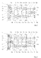
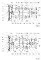
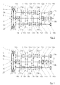
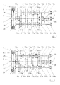
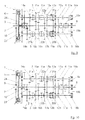
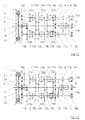
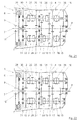
- Fig. 1 shows a first embodiment of a transmission 1, which has two partial transmissions 2 and 3 in the present case, which are referred to below as the first partial transmission 2 and second partial transmission 3.
- the first partial transmission 2 is shown at the top and the second partial transmission 3 respectively below, which is to be regarded as purely exemplary.
- Both partial transmissions 2 and 3 have respective partial transmission shafts 4 and 5, the partial transmission shaft 4 designated by the reference numeral 4 being associated with the first partial transmission 2 and therefore also referred to below as the first partial transmission shaft 4, whereas the partial transmission shaft designated by the reference numeral 5 is the second partial transmission 3 is assigned and therefore hereinafter also referred to as the second partial transmission shaft 5.
- the two partial transmissions 2 and 3 are independently switchable, ie, the respective gear ratios of the two partial transmissions 2 and 3 can be inserted independently. In principle, it is therefore possible that in the two partial transmissions 2 and 3 each have a gear or a "gear" is inserted.
- the transmission 1 further comprises a friction clutch 6, which, like all other components of the transmission 1 in the figures is shown only very schematically and which serves to the occurring during the change between two gear speed differences between a connected to the friction clutch motor output shaft 7 and a leading out of the transmission 1, in a manner not shown with a drive of a motor vehicle, in which the transmission 1 is installed, connected transmission output shaft 8, to bridge.
- the friction clutch 6 may be a multi-plate clutch, a dry clutch or another clutch designed in a manner known per se.
- the transmission 1 has a first, from the friction clutch 6 outgoing transmission input shaft 9 and a friction clutch 6 immediate, with the engine output shaft 7 directly connected second transmission input shaft 10.
- the second transmission input shaft 10 is arranged coaxially in the form of a hollow shaft first transmission input shaft 9.
- the friction clutch 6 may be provided with a recess, not shown.
- the bearings used for mounting the first partial transmission shaft 4, the second partial transmission shaft 5, the engine output shaft 7, the transmission output shaft 8, the first transmission input shaft 9 and the second transmission input shaft 10 are shown schematically in the figures, but these are not described in detail and are not provided with reference numerals, as they play no essential role for the invention.
- An idea connecting all embodiments of the transmission 1 described herein is that the partial transmission shaft 4 of the first partial transmission 2 with the first transmission input shaft 9 and / or the second transmission input shaft 10 is operatively connected, and that the partial transmission shaft 5 of the second partial transmission 3 with the second Transmission input shaft 10 and / or the first transmission input shaft 9 can be brought into operative connection.
- the motor output shaft 7 can be connected by closing the friction clutch 6 via the friction clutch 6 and the first transmission input shaft 9 with the first partial transmission shaft 4 of the first partial transmission 2. In the case where the friction clutch 6 is opened, this connection is broken.
- the second partial transmission shaft 5 of the second partial transmission 3 is constantly connected directly to the engine output shaft 7 via the second transmission input shaft 10.
- the first partial transmission 2 has in the in the FIGS. 1 to 13 illustrated embodiment, seven gear ratios for respective forward gears and a gear stage for a reverse gear.
- the second partial transmission 3 has the identical gear ratios for the seven forward gears and the reverse gear, which are designated by the reference numeral 11b to 18b.
- the gear stages 11a to 18a and 11b to 18b are in the present case in a conventional manner in each case by gear pairs.
- All gear stages 11a to 18a of the first partial transmission 2 and all gear stages 11b to 18b of the second partial transmission 3 can be actuated by means of respective switching elements.
- the first gear 11a is a switching element 19a
- the second and third gear 12a and 13a a common Switching element 20a
- the fourth and fifth gear 14a and 15a associated with a common switching element 21a and the sixth and seventh gear 16a and 17a a common switching element 22a.
- the second partial transmission 3 the assignment of a switching element 19b to the first gear 11b, a common switching element 20b to the two gear stages 12b and 13b, a common switching element 21b to the two gear stages 14b and 15b and a common switching element 22b to the two grades 16b and 17b.
- the switching elements 19a, 19b, 20a, 20b, 21a, 21b, 22a and 22b are each formed as a form-locking, power-operated switching elements, which are deactivated in case of elimination of the same actuating actuation force.
- the positive-locking switching elements 19a, 19b, 20a, 20b, 21a, 21b, 22a and 22b may be jaw clutches, which is based on Fig. 25 will be described in more detail later.
- Fig. 6 was after opening the friction clutch 6 in the first partial transmission 2 by corresponding actuation of the associated switching element 19 a and the first gear 11 a solved, so that in the first partial transmission 2 no gear is engaged.
- the in Fig. 13 illustrated step, in which simultaneously with the closing of the friction clutch 6, the switching element 20b of the second partial transmission 3 is released, so that the second gear 12b is taken out in the second partial transmission 3 and, since the third gear 13a in the second partial transmission 3 was already inserted , the drive of the motor vehicle via the friction clutch 6, the first partial transmission shaft 4 and the third gear 13a takes place on the transmission output shaft 8.
- the other switching operations can be performed in a similar manner, with the downshift being performed in reverse order.
- the transmission 1 has the two partial transmissions 2 and 3 with the respective partial transmission shafts 4 and 5, the friction clutch 6, the engine output shaft 7, the transmission output shaft 8, the first transmission input shaft 9 and the second transmission input shaft 10.
- the two partial transmissions 2 and 3 do not have all the gear ratios. Since the gear stages are all only once available, they were in the embodiment of the FIGS. 14 to 25 denoted by the reference numerals 11 to 18.
- the second gear 12, the fourth gear 14, the sixth gear 16 and the reverse gear 18 are present in the first partial transmission 2, whereas the first gear 11, the third gear 13, the fifth gear 15 and the seventh Gear stage 17 are arranged in the second partial transmission 3.
- this assignment of the gears 11 to 18 has been found to be useful to the two partial transmissions 2 and 3, but it is of course also possible to assign the gear stages 11 to 18 to the two partial transmissions 2 and 3 in a different way.
- the standing with the transmission means 25 and 27 in operative connection switching elements 26 and 28 are designed as a form-locking, power-operated switching elements, which are deactivated when eliminating the force acting on them actuation force.
- these form-fitting switching elements 26 and 28 can be jaw clutches, which, as mentioned above, with reference to Fig. 25 will be described in more detail.
- the transmission means 25, 27, 29 and 31 are formed in the present case as gear pairs, wherein one of the gears on the first transmission input shaft 9 or the second transmission input shaft 10 and the other gear on the first partial transmission shaft 4 or the second partial transmission shaft 5 is arranged.
- the gear stages 11 to 18 are provided with respective switching elements which are able to engage or disengage the individual gear stages 11 to 18.
- the first gear 11 and the third gear 13 is a common switching element 33, the gear 18 for reverse gear and the second gear 12, a common switching element 34, the fourth gear 14 and the sixth gear 16, a common switching element 35 and the fifth Gear stage 15 and the seventh gear 17 associated with a common switching element 36.
- the aforementioned switching elements 33 to 36 may be performed in a conventional manner and serve as mentioned to insert or release the respective gear stage 11 to 18. In contrast to that with reference to the FIGS.
- the switching elements 19b to 22b are formed as a form-locking switching elements
- the switching elements 33 to 36 of the reference to the FIGS. 14 to 24 formed transmission 1 in a conventional manner and provided with synchronizers and the like.
- the switching elements 26 and 28 connected to the transmission transmission shaft 10 connected to the second transmission output shaft 10 the two switching elements 30 and 32 acting on the transmission means 29 and 31 connected to the first transmission input shaft 9 are also provided with synchronizers.
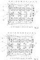
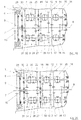
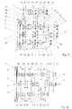
- Fig. 14 shows the resting state of the transmission 1, in which no gear stage is engaged in any of the two partial transmissions 2 and 3.
- the two switching elements 30 and 32 of the two transmission means 29 and 31 were actuated, so that the outgoing of the friction clutch 6 first transmission input shaft 9 is connected to the two partial transmission shafts 4 and 5.
- the friction clutch 6 may be located in the open or the closed position, since in each of the two partial transmission 2 or 3, a gear is engaged. This condition can be called a basic position.
- Fig. 21 shows a switching state in which in the first partial transmission 2 by means of the switching element 34, the second gear 12 was inserted. Since the friction clutch 6 is still open, however, there is no connection of this second gear 12 with the transmission output shaft 8. Rather, this serves as a preparation to switch the transmission 1 in a subsequent step in the second gear 12.
- a jaw clutch is shown which can be seen for both the switching elements 19b, 20b, 21b and 22b with reference to FIGS FIGS. 1 to 13 described first embodiment of the transmission 1 as well as for the switching elements 26 and 28 of the described with reference to the figures 14 to 24 second embodiment of the transmission 1 can be used. It can be seen that this is a part of a dog clutch with two coupling halves, in which a projection 37 of a coupling half 38 engages in a recess 39 of a second coupling half 40, wherein between the projection 37 and the recess 39 is a positive connection.
- the projection 37 and the recess 39 have mutually corresponding inclined surfaces whose angle is selected so that in a loss of operating force, the two coupling halves 38 and 40 separate from each other.
- the force acting on at least one of the two coupling halves 38 and 40 force is applied hydraulically.
- an electric motor can be used to adjust the switching elements electrically.
- switching elements 19b, 20b, 21b and 22b or 26 and 28 could be used.
- the switching elements 19b, 20b, 21b and 22b or 26 and 28, which are in communication with the motor output shaft 7, are not designed as form-locking, force-actuated switching elements, but instead use a device which converts the corresponding switching elements into their respective gear stage does not actuate position.
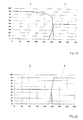
- FIGS. 26 to 29 For example, various exemplary torque curves when upshifting from a gear stage 11 to 16 to one of the gear stages 12 to 17 of one of the transmissions 1 described herein are shown.
- the torque applied to the first transmission input shaft 9 or to the second transmission input shaft 10 is plotted in percent of the maximum torque over time in milliseconds.
- the curve marked "A” shows the torque curve of the transmission input shaft 9 or 10 connected directly to the engine output shaft 7, whereas the curve labeled "B" shows the torque curve on the transmission input shaft 9 or 10 connected to the friction clutch 6.
- FIG. 28 An optimized shift strategy is in Fig. 28 shown.
- the friction clutch 6 is already in engagement before the torque is reduced at the directly connected to the engine output shaft 7 transmission input shaft 9 or 10. This results in a switching time of about 10 ms from the beginning of the reduction of the torque directly connected to the engine output shaft 7 transmission input shaft 9 or 10 until reaching the desired and lower due to the upshift in a higher gear torque at the connected to the friction clutch 6 transmission input shaft 9 or 10. With this short switching time there is in principle no interruption of traction.
- the torque of the directly connected to the engine output shaft 7 transmission input shaft 9 or 10 can be reduced before the switching operation. This is done by reducing the torque of the motor output shaft 7 having drive motor, which may be, for example, an internal combustion engine, but also an electric motor.
- Fig. 30 shows a diagram in which an exemplary torque profile when downshifting of one of the gear stages 12 to 17 in one of the gear stages 11 to 16 of one of the transmission 1 described herein is shown.
- This switching strategy corresponds in principle to in Fig. 28 shown switching strategy when upshifting, ie it is achieved a very short switching time.
- the torque at the transmission input shaft 9 or 10 connected directly to the engine output shaft 7 is shown by the curve "A"
- the torque at the transmission input shaft 9 or 10 connected to the friction clutch 6 is shown by the curve "B".
- the above with reference to the Figures 26 . 27 . 28 and 29 described switching strategies can also be applied to the shift strategy when downshifting.
- a third partial transmission 41 available.
- the gear ratios 11 to 18 are provided, wherein the first gear 11 and the gear stage 18 are arranged for the reverse gear directly on the engine output shaft 7.
- the fourth gear 14 and the seventh gear 17 are arranged on the first sub-transmission shaft 4 of the first sub-transmission 2
- the third gear 13 and the sixth gear 16 are arranged on the second sub-transmission shaft 5 of the second sub-transmission 3
- the second gear 12 and the fifth gear 15 are arranged on a third sub-transmission shaft 42 of the third sub-transmission 41.
- the transmission means 25, 27, 29 and 31 with the same associated switching elements 26, 28, 30 and 32 are also provided here.
- a transmission means 43 connected to the second transmission input shaft 10 and cooperating with the same associated switching element 44 and connected to the first transmission input shaft 9 transmission means 45 with a same associated switching element 46 are provided for the third partial transmission 41.
- the first transmission input shaft 9 is thus brought about the transmission means 29, 31 and 45 and the same associated switching elements 30, 32 and 46 with the three sub-transmission shafts 4, 5 and 41 in operative connection.
- the second transmission input shaft 10 can be brought into operative connection with the three partial transmission shafts 4, 5 and 41 via the transmission means 25, 27 and 43 and the switching elements 26, 29 and 44 associated therewith.
- the third partial transmission 41 is not arranged in a plane with the two partial transmissions 2 and 3, as in Fig. 31 is shown, but spatially offset from the sheet level. This is indicated by the arrows "C".
- the three partial transmissions 2, 3 and 41 are arranged in the manner of a triangle.
- each of the gear stages 11 to 17 is associated with a corresponding switching element.
- a switching element 47 is provided, for actuating the two gear stages 13 and 16 of the second partial transmission 3, a switching element 48 is provided and for actuating the two speed stages 12 and 15 of the third partial transmission 41 is a further switching element 49 is provided.
- the operation of the switching elements 47, 48 and 49 corresponds to that of the switching elements 33 to 36 of the in the FIGS. 14 to 24 illustrated embodiment of the transmission. 1
- FIG. 31 illustrated transmission 1 with the three partial transmissions 2, 3 and 41 may, in principle, analogous to that in the FIGS. 14 to 24 shown gear 1 operated with the two partial transmissions 2 and 3.
- gear 1 operated with the two partial transmissions 2 and 3.
- each shift a greater selection of gear changes is possible because of each of the partial transmissions 2, 3 and 41 can be switched to each other partial transmission 2, 3 and 41, ie there are always two partial transmission available, in which a gear change can take place , This allows greater flexibility when changing gears.
- the third partial transmission 41 it is conceivable to provide additional partial transmissions.
- Fig. 32 is a further embodiment of the transmission 1 is shown. It is a modified form of the in the FIGS. 14 to 24 illustrated embodiment of the transmission 1, but in which the two transmission input shafts 9 and 10 are each connected to two additional transmission means having different translations. In principle, in the case of the embodiment of the FIGS. 14 to 24 existing transmission means 25, 27, 29 and 31 replaced by two transmission means.
- the second transmission input shaft 10 are each assigned two transmission means 50 and 51 having a low gear ratio, and two transmission means 52 and 53 having a higher gear ratio.
- the transmission means 50 and 52 can be switched by means of a switching element 54 arranged between them.
- the transmission means 51 and 53 are switched by means of a switching element 55 arranged between them.
- the two transmission means 50 and 52 of the first partial transmission shaft 4 of the first sub-transmission 2 are assigned, the two transmission means 51 and 53 of the second sub-transmission shaft 5 of the second sub-transmission 3 are assigned.
- the first transmission input shaft 9 is associated with respective transmission means 56 and 57 with a low gear ratio and respective transmission means 58 and 59 with a higher gear ratio.
- transmission means 50, 51, 52 and 53 can be switched between the two transmission means 56 and 58 by means of a switching element 60 and between the two transmission means 57 and 59 by means of a switching element 61 to switch from the lower to the higher translation and vice versa.
Landscapes
- Engineering & Computer Science (AREA)
- General Engineering & Computer Science (AREA)
- Mechanical Engineering (AREA)
- Structure Of Transmissions (AREA)
- Transmission Devices (AREA)
Priority Applications (5)
| Application Number | Priority Date | Filing Date | Title |
|---|---|---|---|
| EP13195138.6A EP2878856A1 (fr) | 2013-11-29 | 2013-11-29 | Engrenage et procédé pour le faire fonctionner |
| EP14805531.2A EP3074660A1 (fr) | 2013-11-29 | 2014-11-24 | Boîte de vitesses et procédé pour la faire fonctionner |
| CN201480071975.1A CN106104077A (zh) | 2013-11-29 | 2014-11-24 | 变速器和用于操作其的方法 |
| PCT/EP2014/075386 WO2015078805A1 (fr) | 2013-11-29 | 2014-11-24 | Boîte de vitesses et procédé pour la faire fonctionner |
| US15/100,230 US20170002899A1 (en) | 2013-11-29 | 2014-11-24 | Transmission and method for operating same |
Applications Claiming Priority (1)
| Application Number | Priority Date | Filing Date | Title |
|---|---|---|---|
| EP13195138.6A EP2878856A1 (fr) | 2013-11-29 | 2013-11-29 | Engrenage et procédé pour le faire fonctionner |
Publications (1)
| Publication Number | Publication Date |
|---|---|
| EP2878856A1 true EP2878856A1 (fr) | 2015-06-03 |
Family
ID=49680884
Family Applications (2)
| Application Number | Title | Priority Date | Filing Date |
|---|---|---|---|
| EP13195138.6A Withdrawn EP2878856A1 (fr) | 2013-11-29 | 2013-11-29 | Engrenage et procédé pour le faire fonctionner |
| EP14805531.2A Withdrawn EP3074660A1 (fr) | 2013-11-29 | 2014-11-24 | Boîte de vitesses et procédé pour la faire fonctionner |
Family Applications After (1)
| Application Number | Title | Priority Date | Filing Date |
|---|---|---|---|
| EP14805531.2A Withdrawn EP3074660A1 (fr) | 2013-11-29 | 2014-11-24 | Boîte de vitesses et procédé pour la faire fonctionner |
Country Status (4)
| Country | Link |
|---|---|
| US (1) | US20170002899A1 (fr) |
| EP (2) | EP2878856A1 (fr) |
| CN (1) | CN106104077A (fr) |
| WO (1) | WO2015078805A1 (fr) |
Cited By (2)
| Publication number | Priority date | Publication date | Assignee | Title |
|---|---|---|---|---|
| EP3171049A1 (fr) | 2015-11-18 | 2017-05-24 | Ricardo Deutschland GmbH | Agencement de couplage |
| US10767734B2 (en) * | 2015-09-02 | 2020-09-08 | Hyundai Motor Company | Transmission for vehicle |
Families Citing this family (2)
| Publication number | Priority date | Publication date | Assignee | Title |
|---|---|---|---|---|
| AT514542B1 (de) * | 2013-06-06 | 2015-04-15 | Avl List Gmbh | Doppelkupplungsgetriebe für ein Kraftfahrzeug |
| DE102022107915C5 (de) * | 2022-04-02 | 2025-12-24 | Wilfried Donner | Verbessertes Schalten von Axialkupplungen mit Flachverzahnungen unter Last |
Citations (6)
| Publication number | Priority date | Publication date | Assignee | Title |
|---|---|---|---|---|
| DE958081C (de) * | 1952-05-07 | 1957-02-14 | Georg Heim | Ohne Unterbrechung der Zugkraft schaltbares Zahnraederwechselgetriebe, insbesondere fuer schwere Kraftfahrzeuge |
| JPS6057033A (ja) * | 1983-09-06 | 1985-04-02 | Aisin Seiki Co Ltd | 自動車用動力伝達装置 |
| DE19853824A1 (de) | 1998-11-21 | 2000-05-31 | Getrag Getriebe Zahnrad | Automatisierbarer Kraftfahrzeug-Antriebsstrang sowie Verfahren zum Steuern eines solchen Antriebsstranges |
| DE19924501A1 (de) * | 1999-05-28 | 2000-12-28 | Daimler Chrysler Ag | Lastschaltbares Stufenwechselgetriebe |
| DE10338558A1 (de) * | 2002-08-23 | 2004-03-04 | Luk Lamellen Und Kupplungsbau Beteiligungs Kg | Verfahren, Vorrichtung und deren Verwendung zum Betrieb eines Kraftfahrzeuges |
| JP2005195115A (ja) * | 2004-01-08 | 2005-07-21 | Honda Motor Co Ltd | 車両用変速機 |
Family Cites Families (2)
| Publication number | Priority date | Publication date | Assignee | Title |
|---|---|---|---|---|
| DE102009023437A1 (de) * | 2009-05-29 | 2010-12-09 | Daimler Ag | Getriebevorrichtung |
| DE102013211591B4 (de) * | 2013-06-20 | 2024-03-28 | Zf Friedrichshafen Ag | Anordnung aus einem Getriebe und einer elektrischen Maschine für einen Hybridantrieb und Hybridantrieb |
-
2013
- 2013-11-29 EP EP13195138.6A patent/EP2878856A1/fr not_active Withdrawn
-
2014
- 2014-11-24 US US15/100,230 patent/US20170002899A1/en not_active Abandoned
- 2014-11-24 EP EP14805531.2A patent/EP3074660A1/fr not_active Withdrawn
- 2014-11-24 WO PCT/EP2014/075386 patent/WO2015078805A1/fr not_active Ceased
- 2014-11-24 CN CN201480071975.1A patent/CN106104077A/zh active Pending
Patent Citations (6)
| Publication number | Priority date | Publication date | Assignee | Title |
|---|---|---|---|---|
| DE958081C (de) * | 1952-05-07 | 1957-02-14 | Georg Heim | Ohne Unterbrechung der Zugkraft schaltbares Zahnraederwechselgetriebe, insbesondere fuer schwere Kraftfahrzeuge |
| JPS6057033A (ja) * | 1983-09-06 | 1985-04-02 | Aisin Seiki Co Ltd | 自動車用動力伝達装置 |
| DE19853824A1 (de) | 1998-11-21 | 2000-05-31 | Getrag Getriebe Zahnrad | Automatisierbarer Kraftfahrzeug-Antriebsstrang sowie Verfahren zum Steuern eines solchen Antriebsstranges |
| DE19924501A1 (de) * | 1999-05-28 | 2000-12-28 | Daimler Chrysler Ag | Lastschaltbares Stufenwechselgetriebe |
| DE10338558A1 (de) * | 2002-08-23 | 2004-03-04 | Luk Lamellen Und Kupplungsbau Beteiligungs Kg | Verfahren, Vorrichtung und deren Verwendung zum Betrieb eines Kraftfahrzeuges |
| JP2005195115A (ja) * | 2004-01-08 | 2005-07-21 | Honda Motor Co Ltd | 車両用変速機 |
Cited By (2)
| Publication number | Priority date | Publication date | Assignee | Title |
|---|---|---|---|---|
| US10767734B2 (en) * | 2015-09-02 | 2020-09-08 | Hyundai Motor Company | Transmission for vehicle |
| EP3171049A1 (fr) | 2015-11-18 | 2017-05-24 | Ricardo Deutschland GmbH | Agencement de couplage |
Also Published As
| Publication number | Publication date |
|---|---|
| EP3074660A1 (fr) | 2016-10-05 |
| US20170002899A1 (en) | 2017-01-05 |
| CN106104077A (zh) | 2016-11-09 |
| WO2015078805A1 (fr) | 2015-06-04 |
Similar Documents
| Publication | Publication Date | Title |
|---|---|---|
| EP2499400B1 (fr) | Dispositif de commutation; et procédé de commande de changement de vitesses de doubleur de gamme automatisé | |
| DE102008010064B4 (de) | Automatgetriebe mit wenigstens einem Planetensatz | |
| DE102004058475A1 (de) | Aktuatoranordnung mit Schaltwalzen für ein Doppelkupplungsgetriebe | |
| EP2722565B1 (fr) | Dispositif de changement de vitesse pour une boîte de vitesses à double embrayage d'un véhicule automobile ou boîte de vitesses à double embrayage dotée d'un tel dispositif de changement de vitesse | |
| DE102013200646B4 (de) | Verfahren zum Schalten eines in Gruppenbauweise ausgeführten Kraftfahrzeuggetriebes | |
| DE10231547A1 (de) | Schaltvorrichtung | |
| WO2014187457A1 (fr) | Boîte de vitesses à double embrayage pourvue de deux tambours de changement de vitesse et d'un nombre mixte de vitesses sur les arbres de transmission partiels | |
| DE102008048902B4 (de) | Gangschaltungssteuerungssystem für ein Automatikgetriebe | |
| EP2426383B1 (fr) | Procédé de suppression d'une position dent sur dent | |
| EP2918877B1 (fr) | Agencement de commutation pour une boîte de vitesses de véhicule automobile et procédé de commutation | |
| EP2878856A1 (fr) | Engrenage et procédé pour le faire fonctionner | |
| DE102018207859B3 (de) | Verfahren und Steuerungseinrichtung zum Betreiben eines Antriebsstrangs | |
| AT512917B1 (de) | Verfahren zum Betreiben eines Doppelkupplungsgetriebes | |
| AT512171B1 (de) | Schaltvorrichtung für ein zahnräderwechselgetriebe, insbesondere für automatik-doppelkupplungsgetriebe | |
| DE102014115373B4 (de) | Schaltanordnung für ein Kraftfahrzeuggetriebe und Schaltverfahren | |
| EP1753982B1 (fr) | Procede de commande d'une transmission automatique | |
| DE102011119833B4 (de) | Schaltvorrichtung für Doppelkupplungsgetriebe in Kraftfahrzeugen | |
| DE102014115371B4 (de) | Schaltanordnung für ein Kraftfahrzeuggetriebe und Schaltverfahren | |
| DE102012203582B4 (de) | Verfahren zur Schaltsteuerung eines automatisierten Gruppengetriebes | |
| DE102012209263A1 (de) | Schaltvorrichtung und Verfahren zur Schaltsteuerung eines Doppelkupplungsgetriebes | |
| DE102019205392B3 (de) | Manuelles Doppelkupplungsgetriebe für ein Kraftfahrzeug | |
| DE102006058973B4 (de) | Verfahren und Vorrichtung zum Steuern des Betriebes eines Parallelschaltgetriebes | |
| DE102019219958B4 (de) | Verfahren zur Schaltsteuerung eines automatisierten Schaltgetriebes | |
| DE102019206746A1 (de) | Verfahrung zur Steuerung der Schaltungen der Gangstufen eines Getriebes eines Fahrzeuges, insbesondere eines Kraftfahrzeuges | |
| EP1300601A1 (fr) | Elément d'accouplement pour changer le rapport de transmission d'un système d'engrenages, sans interrompre le moment de torsion |
Legal Events
| Date | Code | Title | Description |
|---|---|---|---|
| PUAI | Public reference made under article 153(3) epc to a published international application that has entered the european phase |
Free format text: ORIGINAL CODE: 0009012 |
|
| 17P | Request for examination filed |
Effective date: 20131129 |
|
| AK | Designated contracting states |
Kind code of ref document: A1 Designated state(s): AL AT BE BG CH CY CZ DE DK EE ES FI FR GB GR HR HU IE IS IT LI LT LU LV MC MK MT NL NO PL PT RO RS SE SI SK SM TR |
|
| AX | Request for extension of the european patent |
Extension state: BA ME |
|
| STAA | Information on the status of an ep patent application or granted ep patent |
Free format text: STATUS: THE APPLICATION IS DEEMED TO BE WITHDRAWN |
|
| 18D | Application deemed to be withdrawn |
Effective date: 20151204 |