EP2878876A1 - Integriertes led-modul - Google Patents
Integriertes led-modul Download PDFInfo
- Publication number
- EP2878876A1 EP2878876A1 EP12881584.2A EP12881584A EP2878876A1 EP 2878876 A1 EP2878876 A1 EP 2878876A1 EP 12881584 A EP12881584 A EP 12881584A EP 2878876 A1 EP2878876 A1 EP 2878876A1
- Authority
- EP
- European Patent Office
- Prior art keywords
- heat
- led
- led module
- conducting
- module
- Prior art date
- Legal status (The legal status is an assumption and is not a legal conclusion. Google has not performed a legal analysis and makes no representation as to the accuracy of the status listed.)
- Withdrawn
Links
Images


Classifications
-
- F—MECHANICAL ENGINEERING; LIGHTING; HEATING; WEAPONS; BLASTING
- F21—LIGHTING
- F21V—FUNCTIONAL FEATURES OR DETAILS OF LIGHTING DEVICES OR SYSTEMS THEREOF; STRUCTURAL COMBINATIONS OF LIGHTING DEVICES WITH OTHER ARTICLES, NOT OTHERWISE PROVIDED FOR
- F21V23/00—Arrangement of electric circuit elements in or on lighting devices
- F21V23/003—Arrangement of electric circuit elements in or on lighting devices the elements being electronics drivers or controllers for operating the light source, e.g. for a LED array
- F21V23/004—Arrangement of electric circuit elements in or on lighting devices the elements being electronics drivers or controllers for operating the light source, e.g. for a LED array arranged on a substrate, e.g. a printed circuit board
- F21V23/005—Arrangement of electric circuit elements in or on lighting devices the elements being electronics drivers or controllers for operating the light source, e.g. for a LED array arranged on a substrate, e.g. a printed circuit board the substrate is supporting also the light source
-
- F—MECHANICAL ENGINEERING; LIGHTING; HEATING; WEAPONS; BLASTING
- F21—LIGHTING
- F21K—NON-ELECTRIC LIGHT SOURCES USING LUMINESCENCE; LIGHT SOURCES USING ELECTROCHEMILUMINESCENCE; LIGHT SOURCES USING CHARGES OF COMBUSTIBLE MATERIAL; LIGHT SOURCES USING SEMICONDUCTOR DEVICES AS LIGHT-GENERATING ELEMENTS; LIGHT SOURCES NOT OTHERWISE PROVIDED FOR
- F21K9/00—Light sources using semiconductor devices as light-generating elements, e.g. using light-emitting diodes [LED] or lasers
- F21K9/20—Light sources comprising attachment means
-
- F—MECHANICAL ENGINEERING; LIGHTING; HEATING; WEAPONS; BLASTING
- F21—LIGHTING
- F21V—FUNCTIONAL FEATURES OR DETAILS OF LIGHTING DEVICES OR SYSTEMS THEREOF; STRUCTURAL COMBINATIONS OF LIGHTING DEVICES WITH OTHER ARTICLES, NOT OTHERWISE PROVIDED FOR
- F21V17/00—Fastening of component parts of lighting devices, e.g. shades, globes, refractors, reflectors, filters, screens, grids or protective cages
- F21V17/10—Fastening of component parts of lighting devices, e.g. shades, globes, refractors, reflectors, filters, screens, grids or protective cages characterised by specific fastening means or way of fastening
- F21V17/101—Fastening of component parts of lighting devices, e.g. shades, globes, refractors, reflectors, filters, screens, grids or protective cages characterised by specific fastening means or way of fastening permanently, e.g. welding, gluing or riveting
-
- F—MECHANICAL ENGINEERING; LIGHTING; HEATING; WEAPONS; BLASTING
- F21—LIGHTING
- F21V—FUNCTIONAL FEATURES OR DETAILS OF LIGHTING DEVICES OR SYSTEMS THEREOF; STRUCTURAL COMBINATIONS OF LIGHTING DEVICES WITH OTHER ARTICLES, NOT OTHERWISE PROVIDED FOR
- F21V29/00—Protecting lighting devices from thermal damage; Cooling or heating arrangements specially adapted for lighting devices or systems
- F21V29/50—Cooling arrangements
- F21V29/70—Cooling arrangements characterised by passive heat-dissipating elements, e.g. heat-sinks
- F21V29/74—Cooling arrangements characterised by passive heat-dissipating elements, e.g. heat-sinks with fins or blades
-
- F—MECHANICAL ENGINEERING; LIGHTING; HEATING; WEAPONS; BLASTING
- F21—LIGHTING
- F21V—FUNCTIONAL FEATURES OR DETAILS OF LIGHTING DEVICES OR SYSTEMS THEREOF; STRUCTURAL COMBINATIONS OF LIGHTING DEVICES WITH OTHER ARTICLES, NOT OTHERWISE PROVIDED FOR
- F21V29/00—Protecting lighting devices from thermal damage; Cooling or heating arrangements specially adapted for lighting devices or systems
- F21V29/50—Cooling arrangements
- F21V29/70—Cooling arrangements characterised by passive heat-dissipating elements, e.g. heat-sinks
- F21V29/74—Cooling arrangements characterised by passive heat-dissipating elements, e.g. heat-sinks with fins or blades
- F21V29/76—Cooling arrangements characterised by passive heat-dissipating elements, e.g. heat-sinks with fins or blades with essentially identical parallel planar fins or blades, e.g. with comb-like cross-section
- F21V29/763—Cooling arrangements characterised by passive heat-dissipating elements, e.g. heat-sinks with fins or blades with essentially identical parallel planar fins or blades, e.g. with comb-like cross-section the planes containing the fins or blades having the direction of the light emitting axis
-
- H—ELECTRICITY
- H05—ELECTRIC TECHNIQUES NOT OTHERWISE PROVIDED FOR
- H05B—ELECTRIC HEATING; ELECTRIC LIGHT SOURCES NOT OTHERWISE PROVIDED FOR; CIRCUIT ARRANGEMENTS FOR ELECTRIC LIGHT SOURCES, IN GENERAL
- H05B45/00—Circuit arrangements for operating light-emitting diodes [LED]
- H05B45/30—Driver circuits
- H05B45/37—Converter circuits
-
- H—ELECTRICITY
- H05—ELECTRIC TECHNIQUES NOT OTHERWISE PROVIDED FOR
- H05B—ELECTRIC HEATING; ELECTRIC LIGHT SOURCES NOT OTHERWISE PROVIDED FOR; CIRCUIT ARRANGEMENTS FOR ELECTRIC LIGHT SOURCES, IN GENERAL
- H05B45/00—Circuit arrangements for operating light-emitting diodes [LED]
- H05B45/40—Details of LED load circuits
- H05B45/44—Details of LED load circuits with an active control inside an LED matrix
- H05B45/46—Details of LED load circuits with an active control inside an LED matrix having LEDs disposed in parallel lines
-
- H—ELECTRICITY
- H05—ELECTRIC TECHNIQUES NOT OTHERWISE PROVIDED FOR
- H05B—ELECTRIC HEATING; ELECTRIC LIGHT SOURCES NOT OTHERWISE PROVIDED FOR; CIRCUIT ARRANGEMENTS FOR ELECTRIC LIGHT SOURCES, IN GENERAL
- H05B45/00—Circuit arrangements for operating light-emitting diodes [LED]
- H05B45/40—Details of LED load circuits
- H05B45/44—Details of LED load circuits with an active control inside an LED matrix
- H05B45/48—Details of LED load circuits with an active control inside an LED matrix having LEDs organised in strings and incorporating parallel shunting devices
-
- F—MECHANICAL ENGINEERING; LIGHTING; HEATING; WEAPONS; BLASTING
- F21—LIGHTING
- F21V—FUNCTIONAL FEATURES OR DETAILS OF LIGHTING DEVICES OR SYSTEMS THEREOF; STRUCTURAL COMBINATIONS OF LIGHTING DEVICES WITH OTHER ARTICLES, NOT OTHERWISE PROVIDED FOR
- F21V17/00—Fastening of component parts of lighting devices, e.g. shades, globes, refractors, reflectors, filters, screens, grids or protective cages
- F21V17/10—Fastening of component parts of lighting devices, e.g. shades, globes, refractors, reflectors, filters, screens, grids or protective cages characterised by specific fastening means or way of fastening
- F21V17/12—Fastening of component parts of lighting devices, e.g. shades, globes, refractors, reflectors, filters, screens, grids or protective cages characterised by specific fastening means or way of fastening by screwing
-
- F—MECHANICAL ENGINEERING; LIGHTING; HEATING; WEAPONS; BLASTING
- F21—LIGHTING
- F21V—FUNCTIONAL FEATURES OR DETAILS OF LIGHTING DEVICES OR SYSTEMS THEREOF; STRUCTURAL COMBINATIONS OF LIGHTING DEVICES WITH OTHER ARTICLES, NOT OTHERWISE PROVIDED FOR
- F21V29/00—Protecting lighting devices from thermal damage; Cooling or heating arrangements specially adapted for lighting devices or systems
- F21V29/50—Cooling arrangements
- F21V29/502—Cooling arrangements characterised by the adaptation for cooling of specific components
- F21V29/503—Cooling arrangements characterised by the adaptation for cooling of specific components of light sources
-
- F—MECHANICAL ENGINEERING; LIGHTING; HEATING; WEAPONS; BLASTING
- F21—LIGHTING
- F21V—FUNCTIONAL FEATURES OR DETAILS OF LIGHTING DEVICES OR SYSTEMS THEREOF; STRUCTURAL COMBINATIONS OF LIGHTING DEVICES WITH OTHER ARTICLES, NOT OTHERWISE PROVIDED FOR
- F21V31/00—Gas-tight or water-tight arrangements
- F21V31/005—Sealing arrangements therefor
-
- F—MECHANICAL ENGINEERING; LIGHTING; HEATING; WEAPONS; BLASTING
- F21—LIGHTING
- F21Y—INDEXING SCHEME ASSOCIATED WITH SUBCLASSES F21K, F21L, F21S and F21V, RELATING TO THE FORM OR THE KIND OF THE LIGHT SOURCES OR OF THE COLOUR OF THE LIGHT EMITTED
- F21Y2105/00—Planar light sources
- F21Y2105/10—Planar light sources comprising a two-dimensional [2D] array of point-like light-generating elements
-
- F—MECHANICAL ENGINEERING; LIGHTING; HEATING; WEAPONS; BLASTING
- F21—LIGHTING
- F21Y—INDEXING SCHEME ASSOCIATED WITH SUBCLASSES F21K, F21L, F21S and F21V, RELATING TO THE FORM OR THE KIND OF THE LIGHT SOURCES OR OF THE COLOUR OF THE LIGHT EMITTED
- F21Y2115/00—Light-generating elements of semiconductor light sources
- F21Y2115/10—Light-emitting diodes [LED]
-
- H—ELECTRICITY
- H05—ELECTRIC TECHNIQUES NOT OTHERWISE PROVIDED FOR
- H05B—ELECTRIC HEATING; ELECTRIC LIGHT SOURCES NOT OTHERWISE PROVIDED FOR; CIRCUIT ARRANGEMENTS FOR ELECTRIC LIGHT SOURCES, IN GENERAL
- H05B45/00—Circuit arrangements for operating light-emitting diodes [LED]
- H05B45/30—Driver circuits
- H05B45/355—Power factor correction [PFC]; Reactive power compensation
-
- H—ELECTRICITY
- H05—ELECTRIC TECHNIQUES NOT OTHERWISE PROVIDED FOR
- H05B—ELECTRIC HEATING; ELECTRIC LIGHT SOURCES NOT OTHERWISE PROVIDED FOR; CIRCUIT ARRANGEMENTS FOR ELECTRIC LIGHT SOURCES, IN GENERAL
- H05B45/00—Circuit arrangements for operating light-emitting diodes [LED]
- H05B45/30—Driver circuits
- H05B45/36—Circuits for reducing or suppressing harmonics, ripples or electromagnetic interferences [EMI]
Definitions
- the present invention relates to the field of light-emitting diode (LED) lighting, and specifically to an integrated LED module.
- LED light-emitting diode
- light sources for street lighting include an incandescent lamp, a high pressure mercury lamp, a high pressure sodium lamp, a metal halide lamp, a fluorescent lamp, and the like.
- These street lamps generally have the following disadvantages: they are less environmentally friendly (mercury, lead, arsenic and other heavy metals contained therein are harmful to the environment), have high energy consumption and a short service life. Therefore, with the enhancement of global environmental protection consciousness, in countries throughout the world, especially in developed countries and regions, environmentally friendly lighting is more widely applied, and an environmentally-friendly light source will gradually substitute for these street lamps.
- An LED module with a 3-5V forward voltage is an environmentally friendly light source that has high efficiency, saves energy, and has a long luminescence lifetime, which is of great significance to environmental protection, energy saving, and protection of human health.
- a conventional LED drive power supply includes an electromagnetic interference (EMI) unit 121, an analog/digital (A/D) conversion unit 122, an input and output isolation unit 123, a constant-voltage and constant-current output and overvoltage and overcurrent (an open circuit and a short circuit) protection unit 124, and a power factor correction (PFC) power supply 125, and the like.
- EMI electromagnetic interference
- A/D analog/digital
- PFC power factor correction
- Fig. 2 is a schematic structural exploded view of a conventional LED lamp. As shown in Fig.
- the LED lamp structure consists of an LED module 10, a heat sink 11 disposed on the back of the LED module 10 and used for dissipating heat from the LED module 10, a power supply housing 12 for receiving a drive power supply, a light-transmitting shade 13 covering an out-light surface of the LED module, a lid body 14 for sealing the power supply housing, a suspension member 15 connected to the lid body, and the like.
- an objective of the present invention is to provide an integrated LED module, so as to solve the problem in the prior art that an LED lamp presented after assembly has a large size and is heavy as a part of a line of a drive power supply in the LED lamp is complicated.
- Another objective of the present invention is to provide an integrated LED module, which is used to solve the problem in the prior art that separate structures of the components in the LED lamp cause a waste of material costs, prolong processing and assembling time, and result in a waste of production costs.
- the present invention provides an integrated LED module, where the integrated LED module at least comprises: a light-transmitting plate, having a heat-conducting substrate and a transparent package that covers the heat-conducting substrate and has a built-in space; an LED array, laid on a circuit board and sealed in the light-transmitting plate by the transparent package; a drive circuit, laid on the circuit board, sealed in the light-transmitting plate by the package, electrically connected to the LED array by the circuit board, and used for converting an external power supply into a 12V-75V forward voltage that drives each LED in the LED array; and a heat sink, having a heat-conducting surface clinging to the light-transmitting plate and a plurality of heat-dissipation fins integrally formed with the heat-conducting surface.
- the plurality of heat-dissipation fins of the heat sink has notches, to form slots for retaining the control panel.
- a periphery of the transparent package has a flange, four corners of the flange are provided with through holes, and the heat-conducting surface of the heat sink has screw holes corresponding to the through holes.
- the LED module in accordance with the present invention further comprises a seal ring, which is circularly disposed on the periphery of the heat-conducting substrate and the circuit board, and is pressed between the transparent package and the heat sink to seal a gap therebetween.
- the light-transmitting plate clings to the heat-conducting surface of the heat sink by screw locking, bonding or fastening.
- the heat-conducting surface of the heat sink and the light-transmitting plate have a heat-conducting medium therebetween, where the heat-conducting medium is a heat-conducting glue, a heat-conducting grease, or a heat-conducting pad.
- power of each LED in the LED array is 1W-4W
- the LED array is a square, rectangular, circular or elongated array arranged by a plurality of singly packaged LEDs, or a square, rectangular, circular or elongated array arranged by LEDs packaged by LED chips on board (COB).
- COB LED chips on board
- the LED array comprises a plurality of parallel groups formed by a plurality of LEDs connected in parallel, where the parallel groups are connected in series.
- the drive circuit comprises: a power supply module, connected to an external alternating current (AC) or direct current (DC) power supply and the LED array, comprising a rectifying unit and an overcurrent overvoltage protection unit connected to the rectifying unit, and used for converting the external power supply into a 12V-75V forward voltage that drives each LED in the LED array; and a control module connected between the power supply module and the LED array, and comprising a plurality of gating switches and a control unit, where the gating switches are disposed corresponding to the parallel groups and used for conducting or cutting off power supply loops of the parallel groups, and the control unit is used for controlling the gating switches to perform a conduction or cutoff operation according to a detected input voltage.
- the control module further comprises a detection unit used for outputting a different gating instruction to the control unit after detecting a different input voltage.
- the integrated LED module in accordance with the present invention has the following beneficial effects:
- the number of electronic components is reduced a lot in the drive circuit, and restrictive elements such as electrolytic capacitors and inductors are removed; therefore, it is possible to combine lines and load and make a standardized light source, which can reduce the size of the entire product; and the lamps can be combined into products with different power by using the standardized light source, thereby reducing design costs, shortening a product development cycle and reducing product costs, shortening time to market, and further controlling product quality.
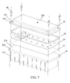
- Fig. 3 is a schematic structural exploded view of an integrated LED module in accordance with the present invention
- Fig. 4 is a schematic structural sectional view of assembly of an integrated LED module consistent with the present invention.
- the present invention provides an integrated LED module, applied to street lighting, industrial lighting and commercial lighting, specifically, for example, stadiums, event plazas, parks and other outdoor venue lighting, or used in many occasions and fields such as lighting and rendering of city beautification buildings.
- the integrated LED module in accordance with the present invention can be assembled into lamps so as to realize convenience and diversification of design and manufacturing of LED lamps.
- the LED module at least comprises: a light-transmitting plate 20, and LED array 21, a drive circuit 22, a heat sink 24, and a control panel 27.
- the light-transmitting plate 20 has a heat-conducting substrate 25, and a transparent package that covers the heat-conducting substrate 25 and has a built-in space 200; specifically, a material of the transparent package comprises plastic, glass, and the like, and the heat-conducting substrate 25 may be made of, for example, metal, FR4, ceramic, silicon or the like.
- the heat-conducting substrate 25, for example, is an aluminum alloy plate with good thermal conductivity
- the transparent package for example, is a transparent plastic encloser with good light transmission properties, and in more details, the transparent plastic encloser may be a light-transmitting shade having a focalization or scattered reflection function.
- each LED in the LED array 21 is an LED 210 with power of 1 W-4W, and in this embodiment, an LED whose power is preferably 1.5W is used as an example for illustration.
- a plurality of LEDs 210 is connected in parallel to form one or more parallel groups, and then the parallel groups are connected in series to form the LED array 21.
- the LED array 21 is a rectangular array arranged by a plurality of singly packaged LEDs 210, but the present invention is not limited thereto, and in other implementation manners, the LED array 21 may also be a square, a rectangular, a circular or an elongated array arranged by a plurality of singly packaged LEDs, or a square, a rectangular, a circular or an elongated array arranged by LEDs packaged by LED COBs.
- the drive circuit 22 is laid on the circuit board 23, sealed in the light-transmitting plate 20 by the package, electrically connected to the LED array 21 by the circuit board 23, and used for converting an external power supply into a 12V-75V forward voltage that drives each LED 210 in the LED array, so as to drive the LED 210 to be turned on.
- the drive circuit 22 preferably converts the external power supply into a 50V forward voltage to drive each LED 210 in the LED array 21.
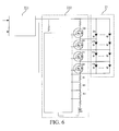
- Fig. 6 which is a view of a circuit principle of an integrated LED module in accordance with the present invention.
- the drive circuit 22 comprises a plurality of electronic elements 220, and the plurality of electronic elements 220 forms a power supply module 221 and a control module 222.
- the power supply module 221 is connected to an external AC or DC power supply and the LED array 21, comprises a rectifying unit and an overcurrent overvoltage protection unit connected to the rectifying unit, and is used for converting the external power supply into a 12V-75V forward voltage that drives each LED in the LED array, so as to drive each LED 210 to be turned on.
- the power supply module 221 is directly connected to AC main power, for example, a 220V AC power supply generally used in China, a 230V AC power supply generally used in Europe, a 110V AC power supply generally used in North America, or a 277V AC power supply generally used in other regions.
- the control module 222 is connected between the power supply module 221 and the LED array 21, and comprises a plurality of gating switches, a control unit and a detection unit, where the gating switches are disposed corresponding to the parallel groups and used for conducting or cutting off power supply loops of the parallel groups, the control unit is used for controlling the gating switches to perform a conduction or cutoff operation according to a detected input voltage, and the detection unit is used for outputting a different gating instruction to the control unit after detecting a different input voltage.
- the control unit for example, is a control chip comprising a peripheral circuit thereof, and the plurality of gating switches is a transistor Q1, a transistor Q2, a transistor Q3, and a transistor Q4.
- the LED array 21 is a series circuit formed by a plurality of parallel groups (for example, the parallel groups D1, D2, D3, D4 shown in Fig. 6 ).
- the plurality of gating switches is a transistor Q1, a transistor Q2, a transistor Q3, and a transistor Q4 that can divide a drive voltage input to the LED array 21 into four stages to take control.
- the control unit makes the transistor Q1 switched on and grounded, so that LED D1 is conducted to the ground;
- the control unit makes the transistor Q1 turned off and the transistor Q2 turned on and grounded, so that LED D1 and D2 are conducted to the ground;
- the control unit makes the transistor Q1 and the transistor Q2 turned off and the transistor Q3 turned on and grounded, so that LED D1, D2 and D3 are conducted to the ground;
- the detection unit detects that the drive voltage input to the LED array 21 reaches a third-stage LED voltage
- the control unit makes the transistor Q1 and the transistor Q2 turned off and the transistor Q3 turned on and grounded, so that LED D1, D2 and D3 are conducted to the ground; and when the detection unit detects that the drive voltage input to the LED array 21
- the heat sink 24 has a heat-conducting surface 240 clinging to the light-transmitting plate 20 and a plurality of heat-dissipation fins 241 integrally formed with the heat-conducting surface 240.
- the heat sink 24 is made of, for example, aluminum with good thermal conductivity, and is formed by means of, for example, aluminum extrusion, aluminum die casting, aluminum lamps, and the like.
- the light-transmitting plate 20 clings to the heat-conducting surface 240 of the heat sink 24 by screw locking, bonding or fastening.
- the heat-conducting surface 240 of the heat sink 24 and the light-transmitting plate 20 have a heat-conducting medium (not shown) therebetween, where the heat-conducting medium is a heat-conducting glue, a heat-conducting grease or a heat-conducting pad.
- the control panel 27 is disposed on the heat-dissipation fins 241, electrically connected to the drive circuit 22, and used for outputting a control instruction to the drive circuit 22 to instruct it to control the LED array 21 to be turned on or turned off, or to adjust brightness or color temperature.
- the control panel 27 comprises a wired or wireless communication module, used for controlling, according to a control instruction sent by a remote control center, the LED array 21 to be turned on or turned off, or to adjust brightness or color temperature.
- the plurality of heat-dissipation fins 241 of the heat sink 24 have notches (not shown), to form slots (not shown) for retaining the control panel 27.
- the control panel 27 may also be fixed to another position of the LED module, for example, be integrated inside the light-transmitting plate 20.
- the LED module at least comprises: a light-transmitting plate 20, an LED array 21, a drive circuit 22, a circuit board 23, a heat sink 24, a heat-conducting substrate 25, and a seal ring 26.
- the light-transmitting plate 20 has a heat-conducting substrate 25, and a transparent package that covers the heat-conducting substrate 25 and has a built-in space 200; specifically, a material of the transparent package comprises plastic, glass, and the like, and the heat-conducting substrate 25 may be made of, for example, metal, FR4, ceramic, silicon and the like.
- the heat-conducting substrate 25, for example is an aluminum alloy plate with good thermal conductivity.
- a periphery of the transparent package has a flange 201, four corners of the flange 201 are provided with through holes 202.
- the transparent package for example, is a transparent plastic encloser with good light transmission properties, and in more details, the transparent plastic encloser may be a light-transmitting shade having a focalization or scattered reflection function.
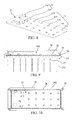
- Fig. 8 is a schematic view of a circuit board provided with an LED array and a drive circuit in the present invention.
- the LED array 21 is laid on a circuit board 23, and is sealed in the light-transmitting plate 20 by the transparent package; in this embodiment, each LED in the LED array 21 is an LED 210 with power of 1 W-4W, and in this embodiment, an LED whose power is preferably 1.5W is used as an example for illustration.
- a plurality of LEDs 210 are connected in parallel to form one or more parallel groups, and then the parallel groups are connected in series to form the LED array 21.
- the drive circuit 22 is laid on the circuit board 23, sealed in the light-transmitting plate 20 by the package, electrically connected to the LED array 21 through the circuit board 23, and used for converting an external power supply into a 12V-75V forward voltage that drives each LED 210 in the LED array, so as to drive the LED 210 to be turned on.
- the drive circuit 22 preferably converts the external power supply into a 50V forward voltage to drive each LED 210 in the LED array 21.
- the drive circuit 22 comprises a plurality of electronic elements 220, and the plurality of electronic elements 220 forms a power supply module and a control module. It should be noted that, a principle of the drive circuit in this embodiment is the same as that in Embodiment 1, which is not repeated herein for simplicity.
- the heat sink 24 has a heat-conducting surface 240 clinging to the light-transmitting plate 20 and a plurality of heat-dissipation fins 241 integrally formed with the heat-conducting surface 240.
- the heat sink 24 is made of, for example, aluminum with good thermal conductivity, which is formed by means of, for example, aluminum extrusion, aluminum die casting, aluminum lamps and the like.
- the heat-conducting surface 240 of the heat sink 24 has screw holes 242 corresponding to the through holes 202.
- the light-transmitting plate 20 is locked to the heat sink 24 by screws 28, which will be detailed later.
- Fig. 9 is a schematic structural sectional view of assembly of another embodiment of an integrated LED module in accordance with the present invention
- Fig. 10 is a top view of another embodiment of an integrated LED module in accordance with the present invention.
- the seal ring 26 is circularly disposed on the periphery of the circuit board 23 and the heat-conducting substrate 25, and is pressed between the transparent package and the heat sink 24 to seal a gap therebetween.
- the seal ring 26, for example is a rubber material or a silicone material with an elastic property and high-temperature resistance.
- the seal ring 26 is pressed between the flange of the transparent package and the heat-conducting surface 240 of the heat sink 24 to seal a gap therebetween, and in this embodiment, the seal ring 26 is disposed in a manner in which the screws 28 penetrate the through holes 202 of the transparent package and are locked to the screw holes 242 of the heat sink 24, so that the seal ring is pressed between the transparent package and the heat sink 24 to seal a gap therebetween.
- the seal ring is directly disposed on the LED module in the lamp, an internal circuit of a conventional lamp is prevented from being damaged due to encloser seepage.
- a lamp formed by the LED module in accordance with the present invention has good waterproof performance.
- the LED module in accordance with the present invention has changed the traditional waterproofing concept, and first proposes a concept of directly disposing a waterproof structure on a built-in module of a lamp, so that an internal circuit of a conventional lamp is prevented from being damaged due to encloser seepage, and thus the lamp having the LED module in accordance with the present invention can be applied in more environments.
- the LED module in accordance with the present invention combines an LED array and a drive circuit into one-piece, they can be assembled to a heat sink in a simple connection manner, to achieve a three-in-one effect, so that the overall size and weight are greatly reduced, thereby effectively reducing the lamp size corresponding thereto, saving materials and saving costs; moreover, the number of electronic components is reduced a lot in the drive circuit, and restrictive elements such as electrolytic capacitors and inductors are removed; therefore, it is possible to combine lines and load and make a standardized light source, which can reduce the size of the entire product; and the lamps can be combined into products with different power by using the standardized light source, thereby reducing design costs, shortening a product development cycle and reducing product costs, shortening time to market, and further controlling product quality. Therefore, the present invention effectively overcomes the defects in the prior art and has a high industrial utilization value.
Landscapes
- Engineering & Computer Science (AREA)
- General Engineering & Computer Science (AREA)
- Microelectronics & Electronic Packaging (AREA)
- Physics & Mathematics (AREA)
- Optics & Photonics (AREA)
- Arrangement Of Elements, Cooling, Sealing, Or The Like Of Lighting Devices (AREA)
- Non-Portable Lighting Devices Or Systems Thereof (AREA)
- Led Device Packages (AREA)
Applications Claiming Priority (3)
| Application Number | Priority Date | Filing Date | Title |
|---|---|---|---|
| CN201210258443.1A CN102818152B (zh) | 2012-07-24 | 2012-07-24 | 一体化集成型led模组 |
| CN2012203889911U CN202733806U (zh) | 2012-08-07 | 2012-08-07 | 具有防水结构的led模组 |
| PCT/CN2012/082010 WO2014015561A1 (zh) | 2012-07-24 | 2012-09-26 | 一体化集成型led模组 |
Publications (2)
| Publication Number | Publication Date |
|---|---|
| EP2878876A1 true EP2878876A1 (de) | 2015-06-03 |
| EP2878876A4 EP2878876A4 (de) | 2016-01-06 |
Family
ID=49996533
Family Applications (1)
| Application Number | Title | Priority Date | Filing Date |
|---|---|---|---|
| EP12881584.2A Withdrawn EP2878876A4 (de) | 2012-07-24 | 2012-09-26 | Integriertes led-modul |
Country Status (3)
| Country | Link |
|---|---|
| US (1) | US9482418B2 (de) |
| EP (1) | EP2878876A4 (de) |
| WO (1) | WO2014015561A1 (de) |
Families Citing this family (12)
| Publication number | Priority date | Publication date | Assignee | Title |
|---|---|---|---|---|
| EP2829795B1 (de) * | 2013-07-23 | 2017-10-18 | OSRAM GmbH | Beleuchtungsvorrichtung und zugehöriges Verfahren zur Montage |
| US9353968B2 (en) * | 2014-03-27 | 2016-05-31 | Daikin Industries, Ltd. | Heat source unit of refrigerating apparatus |
| CN103945605A (zh) * | 2014-04-03 | 2014-07-23 | 吴光 | 一种led驱动电源及led日光灯 |
| WO2015182884A1 (ko) * | 2014-05-29 | 2015-12-03 | 주식회사 포스코엘이디 | 광 반도체 조명장치 |
| JP6691792B2 (ja) * | 2016-02-26 | 2020-05-13 | 株式会社小糸製作所 | 車両用灯具 |
| US10399200B2 (en) * | 2016-12-21 | 2019-09-03 | Ronald Lipson | Intelligent polisher/buffer with selective color-matching light |
| WO2019218329A1 (zh) * | 2018-05-18 | 2019-11-21 | 深圳福凯半导体技术股份有限公司 | 智能感应工矿灯 |
| CN110594601A (zh) * | 2019-10-12 | 2019-12-20 | 佛山市爱居光电有限公司 | 可变色温无线wf可控ac模组 |
| USD924028S1 (en) | 2019-11-04 | 2021-07-06 | B&B Blending, Llc | Polisher |
| CN112325246A (zh) * | 2020-07-08 | 2021-02-05 | 海洋王(东莞)照明科技有限公司 | 壳体结构及灯具 |
| RU200441U1 (ru) * | 2020-07-30 | 2020-10-23 | Общество С Ограниченной Ответственностью "Комлед" | Модульный светодиодный светильник |
| US12158260B2 (en) * | 2021-12-09 | 2024-12-03 | Shenzhen Torshare Technology Co., Ltd. | Lamp control box and lamp |
Family Cites Families (20)
| Publication number | Priority date | Publication date | Assignee | Title |
|---|---|---|---|---|
| US6999318B2 (en) * | 2003-07-28 | 2006-02-14 | Honeywell International Inc. | Heatsinking electronic devices |
| KR101097486B1 (ko) * | 2004-06-28 | 2011-12-22 | 엘지디스플레이 주식회사 | 액정표시장치의 백라이트 유닛 |
| US7125146B2 (en) * | 2004-06-30 | 2006-10-24 | H-Tech, Inc. | Underwater LED light |
| DE102004062990A1 (de) * | 2004-12-22 | 2006-07-06 | Patent-Treuhand-Gesellschaft für elektrische Glühlampen mbH | Beleuchtungseinrichtung mit mindestens einer Leuchtdiode und Fahrzeugscheinwerfer |
| US7284882B2 (en) * | 2005-02-17 | 2007-10-23 | Federal-Mogul World Wide, Inc. | LED light module assembly |
| US20100135020A1 (en) * | 2005-08-15 | 2010-06-03 | Moore Harold A | Modular illumination systems |
| JP5099661B2 (ja) * | 2005-10-28 | 2012-12-19 | 株式会社寺田電機製作所 | Led駆動回路およびled駆動方法 |
| US7307391B2 (en) * | 2006-02-09 | 2007-12-11 | Led Smart Inc. | LED lighting system |
| CN201074792Y (zh) * | 2007-08-16 | 2008-06-18 | 陈照军 | 散热型led灯具 |
| TWM334269U (en) * | 2007-12-07 | 2008-06-11 | Cooler Master Co Ltd | Light-emitting diode (LED) lighting device and lighting module having device |
| TWI407043B (zh) * | 2008-11-04 | 2013-09-01 | Advanced Optoelectronic Tech | 發光二極體光源模組及其光學引擎 |
| CN101749671A (zh) * | 2008-12-18 | 2010-06-23 | 富准精密工业(深圳)有限公司 | 照明装置及其可旋转发光板模组 |
| US20100177511A1 (en) * | 2009-01-10 | 2010-07-15 | Yu qing-lu | Led luminescent light bar |
| KR100961840B1 (ko) * | 2009-10-30 | 2010-06-08 | 화우테크놀러지 주식회사 | 엘이디 램프 |
| TWM364281U (en) * | 2009-04-28 | 2009-09-01 | Kwo Ger Metal Technology Inc | LED light-emitting module |
| US20100277077A1 (en) * | 2009-05-04 | 2010-11-04 | Man Hay Pong | Apparatus and method to enhance the life of Light Emitting diode (LED) devices in an LED matrix |
| CN201515523U (zh) * | 2009-05-27 | 2010-06-23 | 彩虹集团公司 | 一种发光二极管led的驱动装置 |
| EP2284440A1 (de) * | 2009-08-14 | 2011-02-16 | Koninklijke Philips Electronics N.V. | Verbindungsteil zum Verbinden einer Komponenten an einem Kühlkörper |
| US8358081B2 (en) * | 2009-08-21 | 2013-01-22 | Teledyne Technologies Incorporated | Lamp assembly |
| JP2012015148A (ja) * | 2010-06-29 | 2012-01-19 | Rohm Co Ltd | Ledモジュールおよびled照明装置 |
-
2012
- 2012-09-26 WO PCT/CN2012/082010 patent/WO2014015561A1/zh not_active Ceased
- 2012-09-26 EP EP12881584.2A patent/EP2878876A4/de not_active Withdrawn
- 2012-09-26 US US14/416,882 patent/US9482418B2/en active Active
Also Published As
| Publication number | Publication date |
|---|---|
| WO2014015561A1 (zh) | 2014-01-30 |
| US20150204528A1 (en) | 2015-07-23 |
| US9482418B2 (en) | 2016-11-01 |
| EP2878876A4 (de) | 2016-01-06 |
Similar Documents
| Publication | Publication Date | Title |
|---|---|---|
| US9482418B2 (en) | Integrated LED module | |
| CN102782404B (zh) | 具有散热件的照明设备 | |
| US20110292647A1 (en) | Led tube lamp | |
| WO2012139306A1 (zh) | 高出光率led灯泡 | |
| CN102818152B (zh) | 一体化集成型led模组 | |
| CN201935091U (zh) | 一种大功率led汽车前大灯 | |
| CN201475723U (zh) | 液冷配光中空式led灯 | |
| CN203322806U (zh) | 一种线性发光的led光源模组 | |
| CN201836709U (zh) | 外置电源led日光灯 | |
| CN103216755B (zh) | 小型低噪声主动散热的大功率led电光源 | |
| CN201858555U (zh) | 多角度发光的led日光灯管 | |
| SK50662009A3 (sk) | Kompaktné usporiadanie svietidla a kompaktnej LED žiarovky | |
| CN201093219Y (zh) | 一种交流大功率led照明灯 | |
| Yadav et al. | A Review on Light-Emitting-Diodes Characteristics | |
| CN201475710U (zh) | Led节能灯泡 | |
| CN203190161U (zh) | 一种高灵敏度一体式微波感应led灯 | |
| CN103227266B (zh) | Led封装结构 | |
| CN101709840B (zh) | 一种应用导向型发光二极管模块的路灯 | |
| CN101855493B (zh) | 一种大功率led灯 | |
| CN202452231U (zh) | 一种led节能灯 | |
| CN202001966U (zh) | 灯壳散热一体化led吸顶灯 | |
| CN202733806U (zh) | 具有防水结构的led模组 | |
| CN202613142U (zh) | 一种用来取代mr16卤钨灯的高压mr16led灯 | |
| CN203131490U (zh) | 一种列阵集成大功率led组件及led灯具 | |
| CN203784832U (zh) | 整体透镜led模组 |
Legal Events
| Date | Code | Title | Description |
|---|---|---|---|
| PUAI | Public reference made under article 153(3) epc to a published international application that has entered the european phase |
Free format text: ORIGINAL CODE: 0009012 |
|
| 17P | Request for examination filed |
Effective date: 20150223 |
|
| AK | Designated contracting states |
Kind code of ref document: A1 Designated state(s): AL AT BE BG CH CY CZ DE DK EE ES FI FR GB GR HR HU IE IS IT LI LT LU LV MC MK MT NL NO PL PT RO RS SE SI SK SM TR |
|
| AX | Request for extension of the european patent |
Extension state: BA ME |
|
| DAX | Request for extension of the european patent (deleted) | ||
| RA4 | Supplementary search report drawn up and despatched (corrected) |
Effective date: 20151204 |
|
| RIC1 | Information provided on ipc code assigned before grant |
Ipc: F21V 23/00 20150101ALI20151130BHEP Ipc: F21S 2/00 20160101AFI20151130BHEP Ipc: F21K 99/00 20160101ALI20151130BHEP Ipc: F21V 17/12 20060101ALN20151130BHEP Ipc: F21V 29/00 20150101ALI20151130BHEP Ipc: F21Y 105/00 20160101ALN20151130BHEP Ipc: H05B 37/02 20060101ALI20151130BHEP Ipc: F21V 29/76 20150101ALI20151130BHEP Ipc: F21Y 101/02 00000000ALN20151130BHEP Ipc: F21V 31/00 20060101ALN20151130BHEP Ipc: H05B 33/08 20060101ALI20151130BHEP |
|
| 17Q | First examination report despatched |
Effective date: 20160824 |
|
| STAA | Information on the status of an ep patent application or granted ep patent |
Free format text: STATUS: EXAMINATION IS IN PROGRESS |
|
| RIC1 | Information provided on ipc code assigned before grant |
Ipc: F21K 9/20 20160101ALI20171211BHEP Ipc: H05B 37/02 20060101ALI20171211BHEP Ipc: F21V 29/76 20150101ALI20171211BHEP Ipc: F21S 2/00 20160101AFI20171211BHEP Ipc: F21Y 115/10 20160101ALN20171211BHEP Ipc: H05B 33/08 20060101ALI20171211BHEP Ipc: F21V 23/00 20150101ALI20171211BHEP Ipc: F21V 29/00 20150101ALI20171211BHEP Ipc: F21V 17/12 20060101ALN20171211BHEP Ipc: F21Y 105/10 20160101ALN20171211BHEP Ipc: F21V 31/00 20060101ALN20171211BHEP |
|
| GRAP | Despatch of communication of intention to grant a patent |
Free format text: ORIGINAL CODE: EPIDOSNIGR1 |
|
| STAA | Information on the status of an ep patent application or granted ep patent |
Free format text: STATUS: GRANT OF PATENT IS INTENDED |
|
| INTG | Intention to grant announced |
Effective date: 20180201 |
|
| STAA | Information on the status of an ep patent application or granted ep patent |
Free format text: STATUS: THE APPLICATION IS DEEMED TO BE WITHDRAWN |
|
| 18D | Application deemed to be withdrawn |
Effective date: 20180612 |
|
| RIC1 | Information provided on ipc code assigned before grant |
Ipc: H05B 37/02 20060101ALI20171211BHEP Ipc: F21Y 105/10 20160101ALN20171211BHEP Ipc: H05B 33/08 20060101ALI20171211BHEP Ipc: F21Y 115/10 20160101ALN20171211BHEP Ipc: F21K 9/20 20160101ALI20171211BHEP Ipc: F21V 17/12 20060101ALN20171211BHEP Ipc: F21S 2/00 20160101AFI20171211BHEP Ipc: F21V 31/00 20060101ALN20171211BHEP Ipc: F21V 23/00 20150101ALI20171211BHEP Ipc: F21V 29/76 20150101ALI20171211BHEP Ipc: F21V 29/00 20150101ALI20171211BHEP |