EP2878935A1 - Procédé, système et appareil de pesée dynamique de véhicule routier - Google Patents
Procédé, système et appareil de pesée dynamique de véhicule routier Download PDFInfo
- Publication number
- EP2878935A1 EP2878935A1 EP13194770.7A EP13194770A EP2878935A1 EP 2878935 A1 EP2878935 A1 EP 2878935A1 EP 13194770 A EP13194770 A EP 13194770A EP 2878935 A1 EP2878935 A1 EP 2878935A1
- Authority
- EP
- European Patent Office
- Prior art keywords
- wheel
- signal
- footprint
- vehicle
- weight
- Prior art date
- Legal status (The legal status is an assumption and is not a legal conclusion. Google has not performed a legal analysis and makes no representation as to the accuracy of the status listed.)
- Withdrawn
Links
Images

Classifications
-
- G—PHYSICS
- G01—MEASURING; TESTING
- G01G—WEIGHING
- G01G19/00—Weighing apparatus or methods adapted for special purposes not provided for in the preceding groups
- G01G19/02—Weighing apparatus or methods adapted for special purposes not provided for in the preceding groups for weighing wheeled or rolling bodies, e.g. vehicles
Definitions
- the invention relates to road vehicle weigh-in-motion method, system and apparatus, in particular to such method, system and apparatus using fibre-optic sensors.
- the task of measuring a weight of a moving road vehicle also called weigh-in-motion or WIM is important for road management.
- WIM weigh-in-motion
- Analysis of the WIM current trends indicates that fibre-optic sensors are more reliable and durable in comparison to the strain gauge and piezoelectric sensors.
- the traditional methods of calculating a wheel weight, as an integral of a load sensor signal do not provide required accuracy when applied to fibre-optics sensors.
- the problem with accuracy of fibre-optic sensors is, for example, discussed in details in Grakovski et al., 2013.
- the main causes of low accuracy are the blurred front and end parts of the wheel signal and general non-linearity of the sensor's characteristics.
- U.S. Pat. No. 5.260.520 issued Nov. 9, 1993 discloses an apparatus for weighing a vehicle in motion using a plurality of elongated fibre-optic sensors defined by an optical fibre embedded in a casement of electrometric material and disposed parallel to each other on the roadway in the path of a moving vehicle.
- Switch means are used in conjunction with the sensors to provide signals indicative of the speed of the moving vehicle, the number of axles, weight distribution, tire position, and the wheel base of the vehicle.
- the switch means are formed of optical fibres and the extent of light transmission through the fibres during contact with the tire of the vehicle is indicative of the vehicle weight. While the apparatus may be useful in many applications where a high degree of accuracy in weighing vehicles is not essential, it is desirable to improve the accuracy of fibre-optic sensor apparatus for weighing vehicles.
- the object of the present invention is to improve the accuracy of the weigh-in-motion systems which are based on fibre-optics sensors.
- the problem of improving accuracy of measuring road vehicle weight in a weigh-in-motion system based on fibre-optic sensors is solved by decomposing the sensor signal on even and odd components and using the odd component for reconstructing tire footprint and the even component to calculate wheel weight taking into account the footprint area.
- the invention provides a method for road vehicle weigh-in-motion comprising the steps of obtaining wheel load signals from a plurality of elongated fibre-optic sensors embedded in a road surface, each signal being indicative of a wheel load as the vehicle travels across the sensor;
- the step of calculating the wheel weight comprises calculating an integral of the even component of the signal. Still more preferably, the step of calculating the wheel weight comprises calculating of an integral over time from the result of multiplication of the even component of the signal, proportional the pressure, and an instantaneous footprint width, multiplied by the velocity of the vehicle.
- the method comprises the process of linearisation of the even component of the signals prior to using it in the wheel weight calculation.
- the footprint model is in shape of stadium and comprises a first half-ellipse part, a rectangular part, and a second half-ellipse part.
- a model provides a good approximation of the real footprint and four characteristic points that can be aligned with the four extremums of the odd component of the sensor signal.
- the characteristic points of the footprint model are beginning of the footprint, beginning of the rectangular part, end of the rectangular part, end of the footprint, and the characteristic points of the odd component of the signal are first maximum, first minimum, second maximum, and second minimum. In other words, two extremum points from each side of the odd component's point of symmetry are used.
- the step of decomposing the signal into an even and odd components comprises the determination of a centre line of mass for the pulse shape in the signal and using this line position on the time scale as the origin point for the decomposing the signal into even and odd components. Using the centre of mass as the centre for the signal decomposition produces the odd component with clearly distinctive points.
- the method comprises the step of determining an axle weight and/or the total weight of the vehicle as the sum of the weights of the axel wheels and/or the sum of the weights of all wheels of the vehicle.
- the axel weight and total vehicle weight are used in many traffic regulations.
- the invention provides a system for road vehicle weigh-in-motion comprising:
- the plurality of fibre-optic sensors comprises at least one sensor embedded at an angle to transverse direction to the vehicle path.
- the angle between two sensors should be less than 90°, the difference in sensors signals allows to calculate the width of a tire.
- each fibre-optic sensor is installed in a groove made in the road surface.
- the installation in a groove makes the sensor surface even with the road surface, thus the sensors do not disturb the vehicle movements.
- the fibre-optic sensors comprise a fibre-optic cable wound around an elongated core.
- This type of fibre-optic sensors provides a reliable signal that is suitable for the present method for restoring the tire footprint and accurate weighing.
- the invention provides an apparatus for road vehicle weigh-in-motion configured to obtain signals from a plurality of fibre-optic sensors embedded in the road surface, each sensor providing a signal indicative of a wheel loading of a vehicle wheel running over the sensor, the apparatus comprising:
- the processor is being configured to calculate the wheel weight by calculating an integral over time from the result of multiplication of the even component of the signal, proportional the pressure, and an instantaneous footprint width, multiplied by the velocity of the vehicle.
- Fibre-optic sensor - is the sensor where a fibre-optic cable is used as the element of sensing.
- Wheel weight - by the wheel weight in the context of this application is meant the part of the vehicle's weight acting upon the road through the given wheel.
- Centre of mass or centre line of mass for the signal is the point on the time scale (or a line conducted through this point) at which the areas under the left and right parts of the signal are equal.
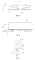
- a weigh-in-motion system 10 generally is composed of the fibre-optic sensors 12-17 installed in the road surface generally transverse to the driving direction 22 and an electronic apparatus 18 for processing the sensor signals.
- the sensors 12-17 are connected with the electronic apparatus 18 by cables 20.
- the fibre-optic sensors 12-17 also comprise an electronic transducer (not shown) for supplying an input light to the sensors and converting the output light into electrical signals
- the electronic apparatus 18 may supply the optical radiation to the sensors 12-17, receive the optical output from the sensors 12-17 and convert it into electrical signals.
- the elongated fibre-optic sensors 12-17 are installed on both sides of the traffic line.
- the fibre-optic sensors 12-17 are embedded into the road surface, by making a grove in the road surface, installing a sensor in the grove and filling the remaining gap with resilient rubber or other elastic material.
- PUR sensors produced- by Sensor Line GmbH are used. The signal in these sensors depends on the change of the transparency and correspondingly the intensity of the light during the deformation. However any other fibre-optic sensors with similar characteristics may be used.
- the sensors 13, 15, and 17 provide the signals from the left wheels of a vehicle running over the sensors, and sensors 12, 14, and 16 provide the signals from the right wheels of the vehicle.
- various vehicle parameters may be determined from the signals of the sensors.
- a time delay between signals from two sensors, for example, sensors 12 and 16 may be used to determine the velocity of the vehicle, whereas a difference in signal duration between signals from two sensors aligned at different angles to the direction of vehicle movement, for example sensors 12 and 14, may be used to determine the tire width.
- FIG. 2 shows a truck 24 having ten wheels 26 and FIG. 3 shows one of the truck wheels 26 running over one of the sensors 12 embedded in the road surface 46. It is clear that at any given moment only part of the tire 28 impacts the sensor 12 and the sensor output represent the tire footprint 30 over time.
- the traditional methods of determining the wheel weight from the length of the tire footprint 30 and the amplitude of the sensor signal, or by integrating the sensor output work well with traditional sensors, for example, strain gouge sensor but do not provide required accuracy when used with the fibre-optic sensors.
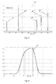
- a road vehicle 24 running over a sensor 12 produces a signal that has a number of separate pulses each pulse representing an impact of one wheel.
- An example of the sensor signal 32 is shown in FIG. 4 .
- a five-axle truck 24 similar to those shown in FIG. 2 may produce a signal similar to the signal 32.
- that signal 34 is used for the wheel weight calculation in the electronic apparatus 18.
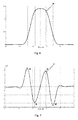
- each wheel load signal 34 is decomposed into even and odd components (36, 37).
- the even component 36 of the signal 34 is shown in FIG. 6 and the odd component 37 in FIG. 7 .
- the decomposition of the wheel signal 34 into even and odd components may be done by any method known in the art. For example, the polynomial approximation using the least square method and the further grouping of the members with even and odd powers separately may be used. Alternatively, standard even-odd decomposition of the signal on finite window may be used. Generally, any known method for decomposition of a function into an even and odd components may be used.
- the odd component 37 has four extremums, designated by lower case letters a, b, c and d.
- FIG. 8 shows a footprint model 38 used in the wheel weight calculation that also has four characteristic points, designated by upper case letters A, B, C, and D.
- the footprint consists of a first half-ellipse (from A to B), a rectangular BC, and a second half-ellipse CD.
- the model is transformed along the time axis so that the characteristic points A, B, C, D of the model be located at the same points on the time axis where the characteristic points a, b, c, d of the odd component 37 are located.
- point A of the model is placed at the time where point a of the odd component 37 of the signal 34 is located, point B of the model is aligned with point b of the signal, C with c and D with d.
- the instantaneous footprint width that is the width of the reconstructed footprint at any given time moment, is used in the further wheel weight calculation.
- the footprint width is defined by ellipse forms for the time intervals from A to B and from C to D and is equal to the tire width W for the time interval from B to C.
- the even component 36 of the wheel signal 34 is indicative of the force with which the wheel or the tire is pressing on the sensor.
- the form of the even component 36 is distorted along the vertical scale because of the non-linearity of the sensors characteristic and the even component 36 needs to be linearised before it can be used in the weight calculation.
- the linearisation may be performed by means of a lookup table as the storage of sensor's characteristics measured in advance for different values of temperature, speed of the wheel, and width of the tire.
- the number of sensor's characteristics measured for different conditions may be stored and a certain characteristic may be used for the linearisation depending on these conditions.
- axle weights are calculated by summarising the weights of the separate wheels belonging to each axle.
- total weight of the vehicle is calculated as either the sum of the wheel weights or as the sum of the axle weights.
- the process of estimating or calculating the weight of the vehicle may be summarised in as follows.
- the signals from the sensors are digitised and stored in the memory.
- the velocity of the vehicle, and the width of the tire are calculated.
- a signal that corresponds to one wheel running over the sensor is chosen and the centre line of mass is determined for this signal and the signal is decomposed into even and odd components taking the centre line of mass location as the origin point for the decomposition.
- the even component of the signal is linearised taking into account the non-linearity of the sensor pressure-output characteristic.
- the tire footprint is reconstructed or the footprint model is aligned with the odd component of the signal.
- the wheel weight is calculated as an integral over time from the result of multiplication of the even component of the signal, and an instantaneous footprint width, multiplied by the velocity of the vehicle.
- the weight calculation is performed for each wheel of the vehicle and the total vehicle weight is calculated as the sum of the wheel weights. If needed, the axle weights may be calculated in the same manner.
- the calibration of the fibre-optic sensors should be conducted twice: at first in the laboratory, and once more, after installing the sensor in the road surface using the vehicles with known weight.
- the electronic apparatus 18 may be further configured to adjust wheel weight calculation taking into account other parameters influencing the sensor response. For example, environment temperature, vehicle acceleration, etc. may be allowed for when calculating wheel weight.
- the present invention may be utilized for road vehicle weigh-in-motion systems.
- the invention provides for the improved accuracy and reliability of weighing road vehicle in motion.
Landscapes
- Physics & Mathematics (AREA)
- General Physics & Mathematics (AREA)
- Force Measurement Appropriate To Specific Purposes (AREA)
Priority Applications (1)
| Application Number | Priority Date | Filing Date | Title |
|---|---|---|---|
| EP13194770.7A EP2878935A1 (fr) | 2013-11-28 | 2013-11-28 | Procédé, système et appareil de pesée dynamique de véhicule routier |
Applications Claiming Priority (1)
| Application Number | Priority Date | Filing Date | Title |
|---|---|---|---|
| EP13194770.7A EP2878935A1 (fr) | 2013-11-28 | 2013-11-28 | Procédé, système et appareil de pesée dynamique de véhicule routier |
Publications (1)
| Publication Number | Publication Date |
|---|---|
| EP2878935A1 true EP2878935A1 (fr) | 2015-06-03 |
Family
ID=49709521
Family Applications (1)
| Application Number | Title | Priority Date | Filing Date |
|---|---|---|---|
| EP13194770.7A Withdrawn EP2878935A1 (fr) | 2013-11-28 | 2013-11-28 | Procédé, système et appareil de pesée dynamique de véhicule routier |
Country Status (1)
| Country | Link |
|---|---|
| EP (1) | EP2878935A1 (fr) |
Cited By (3)
| Publication number | Priority date | Publication date | Assignee | Title |
|---|---|---|---|---|
| CN112255476A (zh) * | 2020-09-22 | 2021-01-22 | 兰州万里航空机电有限责任公司 | 一种应用于飞机舵面锁的自动控制电路 |
| CN116147746A (zh) * | 2022-12-30 | 2023-05-23 | 北京万集科技股份有限公司 | 车辆的称重方法、系统及计算机可读存储介质 |
| CN119413264A (zh) * | 2024-11-08 | 2025-02-11 | 宁波大学 | 一种动态车辆称重系统 |
Citations (1)
| Publication number | Priority date | Publication date | Assignee | Title |
|---|---|---|---|---|
| US5260520A (en) | 1992-04-02 | 1993-11-09 | Martin Marietta Energy Systems, Inc. | Apparatus for weighing and identifying characteristics of a moving vehicle |
-
2013
- 2013-11-28 EP EP13194770.7A patent/EP2878935A1/fr not_active Withdrawn
Patent Citations (1)
| Publication number | Priority date | Publication date | Assignee | Title |
|---|---|---|---|---|
| US5260520A (en) | 1992-04-02 | 1993-11-09 | Martin Marietta Energy Systems, Inc. | Apparatus for weighing and identifying characteristics of a moving vehicle |
Non-Patent Citations (2)
| Title |
|---|
| ALEXANDER GRAKOVSKI ET AL: "Tyre Footprint Reconstruction in the Vehicle Axle Weight-in-Motion Measurement by Fibre-optic Sensors", ICINCO 2013 - PROCEEDINGS OF THE 10TH INTERNATIONAL CONFERENCE ON INFORMATICS IN CONTROL, AUTOMATION AND ROBOTICS; REYKJAVÍK, ICELAND : 2013.07.29-31, SCITEPRESS, ICELAND, vol. 1, 31 July 2013 (2013-07-31), pages 527 - 536, XP008167770, ISBN: 978-989-8565-70-9, DOI: 10.5220/0004620905270536 * |
| GRAKOVSKI, ALEXANDER ET AL.: "Tyre Footprint Reconstruction in the Vehicle Axle Wight-in-Motion Measurement by Fibre-optic Sensors", PROCEEDINGS OF THE 10TH INT. CONF ON INFORMATICS IN CONTROL, AUTOMATION AND ROBOTICS (ICINCO-2013, 2013, pages 527 - 536 |
Cited By (3)
| Publication number | Priority date | Publication date | Assignee | Title |
|---|---|---|---|---|
| CN112255476A (zh) * | 2020-09-22 | 2021-01-22 | 兰州万里航空机电有限责任公司 | 一种应用于飞机舵面锁的自动控制电路 |
| CN116147746A (zh) * | 2022-12-30 | 2023-05-23 | 北京万集科技股份有限公司 | 车辆的称重方法、系统及计算机可读存储介质 |
| CN119413264A (zh) * | 2024-11-08 | 2025-02-11 | 宁波大学 | 一种动态车辆称重系统 |
Similar Documents
| Publication | Publication Date | Title |
|---|---|---|
| EP2932490B1 (fr) | Procédé de mesure d'un véhicule mobile | |
| EA030190B1 (ru) | Датчик, содержащий электрическую линию передачи, параметр которого меняется в зависимости от транспортной нагрузки | |
| EP1573290B1 (fr) | Procede permettant de mesurer les proprietes caracteristiques d'un pneumatique pour roues de vehicules | |
| CN203011351U (zh) | 一种采用光纤光栅传感器的薄板形变测量装置 | |
| EP2878935A1 (fr) | Procédé, système et appareil de pesée dynamique de véhicule routier | |
| Rocheti et al. | Weigh-in-motion systems review: methods for axle and gross vehicle weight estimation | |
| CN113624311A (zh) | 一种多参量的车辆动态称重光纤传感系统 | |
| JP2019109238A (ja) | 加速度センサを備えるwimセンサ、並びにwimセンサを使用してたわみ及び存在を測定する方法 | |
| CN110108340B (zh) | 一种汽车动态称重装置 | |
| US20220042840A1 (en) | Determining weights of vehicles in motion | |
| Ding et al. | Distributed acoustic sensing-based weight measurement method | |
| EP2157002B1 (fr) | Procédé de détermination de la dérive d'un véhicule automobile | |
| CN113639668B (zh) | 一种基于光纤感测技术的角度位移计及其安装方法 | |
| Grakovski et al. | Dynamics of interaction between the road surface and vehicle's wheel in fibre-optic system for automatic weighing in motion of transport | |
| Bin et al. | Study of vehicle weight-in-motion system based on fiber-optic microbend sensor | |
| CN109916487A (zh) | 行车重量智能监控系统及方法 | |
| McCann et al. | System identification for a model-based observer of a road roughness profiler | |
| CN101391568A (zh) | 一种估计车辆悬架行程的方法及实现该方法的装置 | |
| CN207850503U (zh) | 一种行车重量智能监控系统 | |
| US20240337522A1 (en) | In-motion weighing system for motor vehicles based on rigid and fiber optic sensors | |
| CN106872008A (zh) | 一种动态称重传感器横向灵敏度校正方法 | |
| CN215893541U (zh) | 一种基于光纤感测技术的角度位移计 | |
| Tobin Jr et al. | Algorithm for a novel fiber optic weigh-in-motion sensor system | |
| Nieoczym et al. | Geometric optimization of a beam detector for a WIM system | |
| Mihaila et al. | Static calibration of a modified weigh-in-motion sensor |
Legal Events
| Date | Code | Title | Description |
|---|---|---|---|
| PUAI | Public reference made under article 153(3) epc to a published international application that has entered the european phase |
Free format text: ORIGINAL CODE: 0009012 |
|
| 17P | Request for examination filed |
Effective date: 20131128 |
|
| AK | Designated contracting states |
Kind code of ref document: A1 Designated state(s): AL AT BE BG CH CY CZ DE DK EE ES FI FR GB GR HR HU IE IS IT LI LT LU LV MC MK MT NL NO PL PT RO RS SE SI SK SM TR |
|
| AX | Request for extension of the european patent |
Extension state: BA ME |
|
| STAA | Information on the status of an ep patent application or granted ep patent |
Free format text: STATUS: THE APPLICATION IS DEEMED TO BE WITHDRAWN |
|
| 18D | Application deemed to be withdrawn |
Effective date: 20151204 |