EP2878971A1 - Procédé de mesure de la vitesse d'un véhicule se déplaçant sur une route - Google Patents
Procédé de mesure de la vitesse d'un véhicule se déplaçant sur une route Download PDFInfo
- Publication number
- EP2878971A1 EP2878971A1 EP14003812.6A EP14003812A EP2878971A1 EP 2878971 A1 EP2878971 A1 EP 2878971A1 EP 14003812 A EP14003812 A EP 14003812A EP 2878971 A1 EP2878971 A1 EP 2878971A1
- Authority
- EP
- European Patent Office
- Prior art keywords
- speed
- measuring
- measured values
- motor vehicle
- range
- Prior art date
- Legal status (The legal status is an assumption and is not a legal conclusion. Google has not performed a legal analysis and makes no representation as to the accuracy of the status listed.)
- Granted
Links
Images


Classifications
-
- G—PHYSICS
- G01—MEASURING; TESTING
- G01S—RADIO DIRECTION-FINDING; RADIO NAVIGATION; DETERMINING DISTANCE OR VELOCITY BY USE OF RADIO WAVES; LOCATING OR PRESENCE-DETECTING BY USE OF THE REFLECTION OR RERADIATION OF RADIO WAVES; ANALOGOUS ARRANGEMENTS USING OTHER WAVES
- G01S17/00—Systems using the reflection or reradiation of electromagnetic waves other than radio waves, e.g. lidar systems
- G01S17/88—Lidar systems specially adapted for specific applications
-
- G—PHYSICS
- G01—MEASURING; TESTING
- G01S—RADIO DIRECTION-FINDING; RADIO NAVIGATION; DETERMINING DISTANCE OR VELOCITY BY USE OF RADIO WAVES; LOCATING OR PRESENCE-DETECTING BY USE OF THE REFLECTION OR RERADIATION OF RADIO WAVES; ANALOGOUS ARRANGEMENTS USING OTHER WAVES
- G01S13/00—Systems using the reflection or reradiation of radio waves, e.g. radar systems; Analogous systems using reflection or reradiation of waves whose nature or wavelength is irrelevant or unspecified
- G01S13/88—Radar or analogous systems specially adapted for specific applications
- G01S13/91—Radar or analogous systems specially adapted for specific applications for traffic control
- G01S13/92—Radar or analogous systems specially adapted for specific applications for traffic control for velocity measurement
-
- G—PHYSICS
- G01—MEASURING; TESTING
- G01S—RADIO DIRECTION-FINDING; RADIO NAVIGATION; DETERMINING DISTANCE OR VELOCITY BY USE OF RADIO WAVES; LOCATING OR PRESENCE-DETECTING BY USE OF THE REFLECTION OR RERADIATION OF RADIO WAVES; ANALOGOUS ARRANGEMENTS USING OTHER WAVES
- G01S17/00—Systems using the reflection or reradiation of electromagnetic waves other than radio waves, e.g. lidar systems
- G01S17/02—Systems using the reflection of electromagnetic waves other than radio waves
- G01S17/50—Systems of measurement based on relative movement of target
- G01S17/58—Velocity or trajectory determination systems; Sense-of-movement determination systems
-
- G—PHYSICS
- G08—SIGNALLING
- G08G—TRAFFIC CONTROL SYSTEMS
- G08G1/00—Traffic control systems for road vehicles
- G08G1/01—Detecting movement of traffic to be counted or controlled
- G08G1/052—Detecting movement of traffic to be counted or controlled with provision for determining speed or overspeed
- G08G1/054—Detecting movement of traffic to be counted or controlled with provision for determining speed or overspeed photographing overspeeding vehicles
Definitions
- the present invention relates to a method for measuring the speed of a vehicle moving on a road according to the features of claim 1.
- the quality of the measurement result in particular the travel speed, depends on the number of recorded measured values.
- a small number of recorded measured values often provides an inaccurate measurement result, too large a number of measured values leads to an aborted measurement in the case of accelerated or decelerated driving behavior of the motor vehicle.
- a traffic surveillance apparatus for photographic registration of motor vehicles in which a first speed value is obtained by means of Doppler radar on a relatively short, entry-side part of a measuring section and serves to trigger the camera.
- a second speed value is obtained by a plurality of speed measurements over the entire measuring section.
- the DE 10 2007 038 364 A1 discloses a method of measuring speed of a motor vehicle. By means of a laser scanner measured values are recorded with every scan. When the motor vehicle passes through the working area of the laser scanner, a change of position is detected in order to determine the speed therefrom. When a photo line is reached, vehicles driving too fast are captured photographically.
- the distance range of the working area can be limited by being trained specifically for the installation site to areas in which moving objects are expected.
- the measured values that describe a right angle are used for each scan.
- the working range of the laser scanner can be limited to angular ranges that provide measured values that describe a right angle.
- Wave-beam based sensors like the one in the DE 10 2007 038 364 A1 shown laser sensor or laser scanner a relatively large workspace. Although it is known to restrict the work area to certain areas by not capturing the measurements of the entire coverage angle and / or the measurement data of the entire distance range of the work area, these then specified areas are completely read. This has the serious disadvantage that, depending on the speed of the appropriate motor vehicle, there is a different number of measured values. In fast-moving motor vehicles, there are a small number of recorded measured values, which causes the work area to be as large as possible, since otherwise an inaccurate measurement result is delivered. In the case of slow objects, a large number of measured values are present, which causes the working area to be as small as possible, since otherwise acceleration or deceleration may result in termination of the measurement.
- the size of the work area can only be a compromise if both fast and slow moving vehicles are to be reliably detected.
- Such situations are particularly prevalent on highways where, for example, at a speed limit of 80 km / h, lorries slightly exceeding the speed limit, but also heavily motorized passenger cars, can exceed the speed limit many times over.
- a method for measuring the speed of a motor vehicle moving on a road surface comprises the following steps: providing a sensor unit for emitting a measuring radiation into a working range determining a maximum measuring range and receiving a measuring radiation reflected on the motor vehicle; Specify a Number of first measured values; Detecting first measured values obtained by the received measuring radiation in a first partial measuring range of the working range; Canceling the acquisition of first measured values when the predetermined number of measured values is reached; Deriving a traveling speed of the moving motor vehicle from the first measured values obtained by the received measuring radiation in the first partial measuring range of the working range; Comparing the travel speed with a limit speed; Taking a proof by means of a camera, if the travel speed is greater than the limit speed.
- the solution according to the invention ensures fairness by equal treatment of slow speed, high speed speed violations.
- the step of taking a proof is taken with a camera immediately after comparing the travel speed with the limit speed.
- the step of picking up takes place when the motor vehicle is on a predetermined photo line. It is thus preferred to specify such a number of measured values, so that the measurement is completed for typical speeds present in the measuring range before the motor vehicle reaches the predetermined photo line.
- an estimated speed is derived at a time t_recision of the moving motor vehicle from the second measured values obtained by the received measuring radiation in a second partial measuring range of the working range. Subsequently, the acquisition of measured values received by the received measuring radiation in a first partial measuring range of the working range is then started at a time t_Start, so that the detection of the first measured values is stopped before the photo-line.
- the first partial measuring range is optimally adapted to the speed of the motor vehicle, ie a rather large measuring range for high speeds and a smaller measuring range for low speeds.
- the first partial measuring range is arranged in an exit-side part and the second partial measuring area is arranged in an entry-side part of the working area.
- a size of a measuring range is understood according to the invention to mean a measuring length that a motor vehicle leaves on a roadway.
- the maximum measuring range ie the working range
- one partial measuring range or several partial measuring ranges are cut out, in which the Measurements are used to derive a speed, while in the other areas of the work area, the measured values are discarded.
- the second partial measuring range is thus preferably smaller than the first partial measuring range.
- the method step of deriving the first speed and the travel speed from the reflected measuring radiation can be carried out as follows:
- the measuring radiation can be a pulsed laser radiation which scans a horizontal scanning plane repeatedly at a constant scanning frequency and a constant pulse frequency.
- the laser sensor laser scanner
- the laser sensor can be placed next to a roadway at an acute angle to the roadway.
- the laser beam hits motor vehicles in the work area and is reflected.
- the respective impact point is described by a measuring point P n .
- the transit time of the pulsed laser beam to the appropriate motor vehicle and back correlates with the distance traveled, from which a distance e n of the measuring point P n from the roadside positioned laser sensor (laser scanner) derived and a time t n and a current scan angle ⁇ n can be assigned.
- a distance e n of the measuring point P n from the roadside positioned laser sensor (laser scanner) derived and a time t n and a current scan angle ⁇ n can be assigned.
- the measuring points P n can be described with temporal assignment in a polar coordinate system, which is determined by the location and orientation of the laser sensor (laser scanner). From this information, a speed of the motor vehicle can now be derived.
- the measuring radiation may also be radar radiation
- the sensor unit in this exemplary embodiment comprises a radar sensor which emits a radar lobe.
- the radar radiation is reflected on motor vehicles located within the radar lobe, and from the reflection signals or the derived Doppler signals, value triplets are derived in a known manner for the respective impact points on the motor vehicle, each of a distance and an angle value which together determine the position of the impact point within the radar lobe, as well as a speed value.
- the obtained value triplets which are each effected by a point of impact, are combined to form a track and continuously checked for plausibility (so-called "tracking method") by comparing the measured values with calculated setpoint values.
- the setpoints result from the assumption that a motor vehicle makes changes in direction only to a limited extent and accelerates or decelerates only within certain limits.
- the sensor unit may have a first sensor for deriving the first speed and a second sensor for deriving the travel speed include. This ensures that the first speed and the driving speed can be measured independently of each other.
- the size of the first partial measuring range is adapted with a first correction factor. Since hardly any strong dynamic changes are to be expected in the case of very fast motor vehicles, the first part measuring range can be increased by an additional factor in order to detect vehicles with high speeds more reliably. Depending on the location of the measurement, an additional correction factor with respect to the dependence of the estimated speed may also be useful for taking a priori knowledge into account, such as intersections provided with traffic lights. In this case, in slow vehicles, for example, the first part measuring range can be increased or reduced, since when switching to red light, a strong deceleration or acceleration is possible.
- the step of deriving a travel speed comprises the following further features: Defining a termination criterion for deriving a travel speed when a scatter of the first measured values is above a predetermined limit value; Statistical analysis of possible crashes of several motor vehicles; Adjusting the size of the first sub-range with a second correction factor to reduce the number of aborts.
- the detection rate of detected low-speed vehicles can be increased without simultaneously decreasing the detection rate of high-speed vehicles because there are too few speed measurements. This also ensures fairness by equal treatment of slow speed, high speed speed bumps.
- the amount of the predetermined limit value for the scattering of the first measured values is less than or equal to 3%.
- the first and / or second sensor is designed as a radar sensor or laser sensor. Such sensors are particularly suitable for measuring the speed of a motor vehicle.
- the first part measuring range in the direction of travel on a start region and an end region, wherein a distance between the end portion of the first Operamess Schemees and the photo line is at most an average length of a motor vehicle. If the first partial measuring range ends before the photo line, it is preferably provided that the distance to the photo line is so small that if a motor vehicle in the first partial measuring range is adequate, during or after the measuring process no other vehicle can engage between the first partial measuring range and the photo line and thus triggering the taking of evidence the retracted motor vehicle is not photographically recorded and incorrectly assigned to the measured values of the motor vehicle suitable for the first part of the measuring range.
- a preferred embodiment comprises a "and / or" link between a first feature and a second feature, then this is to be read so that the embodiment is either the first feature or the second feature and according to another embodiment, either only the first feature or only the second feature.
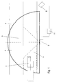
- Fig.1 shows a schematic structure of a first embodiment of an apparatus according to the invention for carrying out a method for speed measurement.
- the device has a sensor unit 3 for emitting a measuring radiation 4 into a working area 5 determining a maximum measuring range and receiving the measuring radiation reflected on a motor vehicle 2.
- the measuring radiation is a strongly focused pulsed laser beam, which is deflected by a rotating or oscillating mirror in a horizontal scanning plane with a constant scanning frequency and a constant pulse rate and which scans the working area several times.
- For the speed measurement is preferably a working range with an expansion angle of ⁇ up to 180 ° suitable.
- the central axis of the working area is at an expansion angle of 180 °, preferably perpendicular to the direction of travel.
- the laser sensor (laser scanner) is placed next to the lane 1.
- the laser beam hits motor vehicles in the work area and is reflected.
- the respective impact point is described by a measuring point P n .
- the duration of the pulsed laser beam to the appropriate motor vehicle and back correlates with the distance traveled, resulting in a distance e n of the Measuring point P n derived from the roadside laser sensor (laser scanner) 3 derived and a time t n and a current scan angle ⁇ n can be assigned.
- a radar sensor which emits a radar lobe which detects a working area with a comparable opening angle.
- the measuring points P n are described with temporal assignment in a polar coordinate system, which is determined by the location and orientation of the laser sensor (laser scanner) 3. From this information, a driving speed of the motor vehicle can now be derived.
- the working area 5 has a first partial measuring area 9. In the case of a radar sensor, this is done in the same way on the basis of the first measured values in the form of Doppler signals, which are combined to form a measured value at a time t1.
- a number of first measured values are now specified. If the predetermined number of first measured values is reached by the received measuring radiation in the first partial measuring range 9 of the working range, the detection of first measured values is stopped. Thus, not the measuring range before the measurement is determined, but the number of measured values. Depending on the driving speed, different sizes thus result for the measuring range. Overall, the solution according to the invention ensures fairness by equal treatment of slow speed, high speed speed violations. From the detected first measured values, a travel speed of the moving motor vehicle is derived and compared with a limit speed. If, then, the travel speed is greater than the limit speed, a taking of evidence is recorded by means of a camera 6. For this purpose, the camera 6 and the sensor unit 3 are connected to one another via a computer and control unit 11.
- Fig. 2 shows a schematic structure of a second embodiment of a device according to the invention for carrying out a method for speed measurement.
- the device and the principles of measuring radiation and measured value acquisition essentially correspond to those in Fig. 1 ,
- the working area 5 has at least a first partial measuring area 9 and a second partial measuring area 8, wherein the size of the first partial measuring area for deriving the traveling speed is chosen as a function of the estimated speed of the motor vehicle 2 derived in the second partial measuring area.
- the estimated speed is derived.
- a few second measured values are needed, which are combined to form a measured value at a time t estim . This is done while entering or passing through the work area, where it is detected how the contour of the vehicle in the work area shifts over time. In the case of a radar sensor, this is done in the same way on the basis of the second measured values in the form of Doppler signals, which are combined to form a measured value at a time t estim .
- the size of the measuring range in which the first measured values are detected is determined.
- the arrow Z shows the time shift of the beginning of the first partial measuring range for different estimated speeds. This means that the beginning of the first measuring range shifts in the direction of travel.
- the travel speed is compared with a limit speed. If the travel speed is greater than the limit speed, a proof is taken by means of a camera 6 when the motor vehicle is on a predetermined photo line 7.
- the camera 6 and the sensor unit 3 are connected to one another via a computer and control unit 11.
- the first partial measuring area 9 is optimally adapted to the speed of the motor vehicle, ie a rather large measuring range for high speeds and a smaller measuring range for low speeds.
- the second partial measuring area 8 is preferably arranged in an entry-side part and the first partial measuring area 9 is arranged in an exit-side part of the working area 5.
- the size of the measuring range is understood to mean the measuring length which the motor vehicle 2 leaves on a roadway 1.
- the maximum measuring range ie in the working range 5
- partial measuring ranges are defined in which the measured values are used to derive a speed, while in the other ranges of the working range the measured values for determining the traveling speed remain unused.
- the first partial measuring range ends independently of the estimated speed at or up to an average vehicle length away from the photo line 7.
- a gap 10 arises between the two partial measuring ranges, which is the smaller, the higher the estimated speed.
- FIG. 3 a third preferred embodiment of a device according to the invention for carrying out a method for speed measurement is shown.
- the device has a sensor unit 3 for emitting a measuring radiation 4 into a working area 5 determining a maximum measuring range and receiving the measuring radiation reflected on a motor vehicle 2.
- the measuring radiation is a strongly focused pulsed laser beam, which is deflected by a rotating or oscillating mirror in a horizontal scanning plane with a constant scanning frequency and a constant pulse rate and which scans the working area several times.
- a working range with a preferred expansion angle of 10 ° ⁇ ⁇ 60 ° is used for the speed measurement.
- the central axis of the working area is rotated between 15 ° and 40 ° counter to the direction of travel at an acute horizontal angle ⁇ in the direction of the roadway.
- the laser sensor (laser scanner) can be placed next to a roadway 1 at an acute angle to the roadway.
- the laser beam strikes motor vehicles located in the working area 5 and is reflected.
- the respective impact point is described by a measuring point P n .
- the transit time of the pulsed laser beam to the appropriate motor vehicle and back correlates with the traveled distance, from which a distance e n of the measuring point P n of the roadside positioned laser sensor (laser scanner) 3 derived and a time t n and a current scan angle ⁇ n can be assigned.
- a radar sensor which emits a radar lobe which detects a working area with a comparable opening angle.
- the working area 5 has at least a first partial measuring area 9 and a second partial measuring area 8, wherein the size of the second partial measuring area for deriving the traveling speed is selected as a function of the first speed of the motor vehicle 2 derived in the first partial measuring area.
- the estimated speed is derived from the comparison of the transmitted radiation and the radiation reflected by the motor vehicle. For the derivation of the estimated speed, only a few second measured values are needed, which are combined to form a measured value at a time t estim . This is done while entering or passing through the work area, in which it is detected how the contour of the vehicle 2 shifts in the work area over time. In the case of a radar sensor, this is done in the same way on the basis of the second measured values in the form of Doppler signals, which are combined to form a measured value at a time t estim .
- the size of the measuring range in which the first measured values are detected, from which the traveling speed of the same vehicle 2 'is determined at a time t start is determined.
- the shift of the beginning of the first part measuring range is shown, the further the beginning of the first measuring range shifts in the direction of travel, the smaller the first measuring range.
- the travel speed is compared with a limit speed, if the travel speed is greater than the limit speed, a proof is taken by means of a camera 6 when the motor vehicle is on a predetermined photo line 7.
- the camera 6 and the sensor unit 3 are connected to one another via a computer and control unit 11.
- the first partial measuring area 9 is optimally adapted to the speed of the motor vehicle, ie a rather large measuring range for high speeds and a smaller measuring range for low speeds.
- the second partial measuring area 8 is preferably arranged in an entry-side part and the first partial measuring area 9 is arranged in an exit-side part of the working area 5.
- the second part measuring range is formed smaller than the area that is available for the maximum part measuring range.
- the second partial measuring range 8 is preferably only so large that, for all motor vehicles with a maximum speed, e.g. An estimation speed can be determined up to 300 km / h.
- the maximum part between the first part measuring area and the photo line is then available to the first partial measuring area when the photo line 7 is arranged within the working area 5 and at most the area between the second partial measuring area and the edge of the exit side part of the working area 5.
- the first partial measuring area ends irrespective of the estimated speed on the photo line 7 or up to an average vehicle length away from the photo line 71. In practice, depending on the estimated speed, a gap 10 arises between the two partial measuring ranges, which is the smaller, the higher the estimated speed.
- the photo-line 7 comes, in a second embodiment, the photo-line 71 is used.
- the embodiment according to Fig. 4 differs from the first three embodiments by the design of the sensor unit 3.
- the sensor unit comprises a first sensor 3a and a second sensor 3b.
- one sensor is assigned to one partial measuring range 8 in each case.
- the first sensor 3a is assigned to the second partial measuring range and the second sensor 3b is assigned to the first partial measuring range 9.
- the second sensor 3b for the first measuring range in which the driving speed is determined has a higher measuring accuracy than the first sensor 3a.
- the first sensor 3a can be made more cost-effective than the second sensor 3b.
- the two sensors can be brought together at one location and / or in a structural unit or be set up at different locations.
- the two independent sensors can be sensors of the same type, in particular laser scanners or radar sensors.
- the first sensor 3a can also be any other active or passive wave-beam-based sensor, the z. B. works with laser beams, radar beams or sound waves.
- Fig. 4 is also a distance 12 between an end portion of the first part measuring range and the photo line 7 located.
- This distance is inventively chosen relatively small, ideally zero to a maximum of an average vehicle length, so that no further second motor vehicle is erroneously associated with the measured values of the appropriate in the first part measuring range motor vehicle.
Landscapes
- Physics & Mathematics (AREA)
- Engineering & Computer Science (AREA)
- Radar, Positioning & Navigation (AREA)
- Remote Sensing (AREA)
- General Physics & Mathematics (AREA)
- Electromagnetism (AREA)
- Computer Networks & Wireless Communication (AREA)
- Optical Radar Systems And Details Thereof (AREA)
- Traffic Control Systems (AREA)
Applications Claiming Priority (1)
| Application Number | Priority Date | Filing Date | Title |
|---|---|---|---|
| DE102013019801.1A DE102013019801B4 (de) | 2013-11-27 | 2013-11-27 | Verfahren zur Geschwindigkeitsmessung eines sich auf einer Straße bewegenden Kraftfahrzeuges |
Publications (2)
| Publication Number | Publication Date |
|---|---|
| EP2878971A1 true EP2878971A1 (fr) | 2015-06-03 |
| EP2878971B1 EP2878971B1 (fr) | 2021-12-29 |
Family
ID=51897058
Family Applications (1)
| Application Number | Title | Priority Date | Filing Date |
|---|---|---|---|
| EP14003812.6A Active EP2878971B1 (fr) | 2013-11-27 | 2014-11-12 | Procédé de mesure de la vitesse d'un véhicule se déplaçant sur une route |
Country Status (2)
| Country | Link |
|---|---|
| EP (1) | EP2878971B1 (fr) |
| DE (1) | DE102013019801B4 (fr) |
Families Citing this family (1)
| Publication number | Priority date | Publication date | Assignee | Title |
|---|---|---|---|---|
| FR3086066B1 (fr) * | 2018-09-13 | 2021-01-29 | Idemia Identity & Security France | Procede et dispositif de controle du fonctionnement d'un radar routier. |
Citations (9)
| Publication number | Priority date | Publication date | Assignee | Title |
|---|---|---|---|---|
| EP0286910A2 (fr) | 1987-04-11 | 1988-10-19 | Robot Foto & Electronic GmbH & Co KG | Dispositif de contrôle du trafic |
| DE3908785A1 (de) * | 1989-03-17 | 1990-09-27 | Bke Bildtechnisches Konstrukti | Verfahren und einrichtungen zur messung der geschwindigkeit von kraftfahrzeugen |
| US6160494A (en) * | 1996-07-26 | 2000-12-12 | Sodi; Paolo | Machine and method for detecting traffic offenses with dynamic aiming systems |
| US20040174294A1 (en) * | 2003-01-10 | 2004-09-09 | Wavetronix | Systems and methods for monitoring speed |
| DE102007038364A1 (de) | 2007-08-10 | 2009-02-12 | Robot Visual Systems Gmbh | Verfahren zur Geschwindigkeitsmessung von Fahrzeugen mittels Laserscanner |
| US20110187580A1 (en) * | 2007-10-09 | 2011-08-04 | Guy Laenen | Device for detecting a vehicle on an airport runway |
| DE102010010656A1 (de) * | 2010-03-09 | 2011-09-15 | Rtb Gmbh & Co. Kg | Klassifizierungsverfahren und -einrichtung für Fahrzeuge |
| US20120188115A1 (en) * | 2011-01-24 | 2012-07-26 | Lang Hong | Using Forward-Look and Side-Look Doppler Radars for Precise Vehicle Association in Automated Traffic Surveillance |
| EP2650696A1 (fr) * | 2012-03-26 | 2013-10-16 | Sierzega Elektronik GmbH | Procédé et dispositif pour le recensement de la circulation |
-
2013
- 2013-11-27 DE DE102013019801.1A patent/DE102013019801B4/de active Active
-
2014
- 2014-11-12 EP EP14003812.6A patent/EP2878971B1/fr active Active
Patent Citations (9)
| Publication number | Priority date | Publication date | Assignee | Title |
|---|---|---|---|---|
| EP0286910A2 (fr) | 1987-04-11 | 1988-10-19 | Robot Foto & Electronic GmbH & Co KG | Dispositif de contrôle du trafic |
| DE3908785A1 (de) * | 1989-03-17 | 1990-09-27 | Bke Bildtechnisches Konstrukti | Verfahren und einrichtungen zur messung der geschwindigkeit von kraftfahrzeugen |
| US6160494A (en) * | 1996-07-26 | 2000-12-12 | Sodi; Paolo | Machine and method for detecting traffic offenses with dynamic aiming systems |
| US20040174294A1 (en) * | 2003-01-10 | 2004-09-09 | Wavetronix | Systems and methods for monitoring speed |
| DE102007038364A1 (de) | 2007-08-10 | 2009-02-12 | Robot Visual Systems Gmbh | Verfahren zur Geschwindigkeitsmessung von Fahrzeugen mittels Laserscanner |
| US20110187580A1 (en) * | 2007-10-09 | 2011-08-04 | Guy Laenen | Device for detecting a vehicle on an airport runway |
| DE102010010656A1 (de) * | 2010-03-09 | 2011-09-15 | Rtb Gmbh & Co. Kg | Klassifizierungsverfahren und -einrichtung für Fahrzeuge |
| US20120188115A1 (en) * | 2011-01-24 | 2012-07-26 | Lang Hong | Using Forward-Look and Side-Look Doppler Radars for Precise Vehicle Association in Automated Traffic Surveillance |
| EP2650696A1 (fr) * | 2012-03-26 | 2013-10-16 | Sierzega Elektronik GmbH | Procédé et dispositif pour le recensement de la circulation |
Also Published As
| Publication number | Publication date |
|---|---|
| DE102013019801B4 (de) | 2018-01-11 |
| DE102013019801A1 (de) | 2015-05-28 |
| EP2878971B1 (fr) | 2021-12-29 |
Similar Documents
| Publication | Publication Date | Title |
|---|---|---|
| EP1990654B1 (fr) | Procédé et dispositif de détermination de la classe de véhicules | |
| DE102012107444B3 (de) | Verfahren zur Klassifizierung von fahrenden Fahrzeugen durch Verfolgung einer Positionsgröße des Fahrzeuges | |
| DE19743255B4 (de) | Erkennungssystem für sich bewegende Objekte für Kraftfahrzeuge | |
| EP2048515B1 (fr) | Procédé pour déterminer et documenter des infractions à un feux de signalisation | |
| DE102012107445B4 (de) | 2Verfahren zur Klassifizierung von fahrenden Fahrzeugen | |
| EP2106530B1 (fr) | Procédé et dispositif pour détecter la surface tridimensionnelle d'un objet, en particulier d'un pneu de véhicule | |
| EP3058391B1 (fr) | Utilisation d'un procédé et d'un dispositif de classification d'obstacles | |
| DE112017003974B4 (de) | Geschwindigkeitsregelungsvorrichtung | |
| EP0936471A2 (fr) | Dispositif de détection d'objets | |
| DE102007022373A1 (de) | Verfahren zur beweiskräftigen Erfassung der Geschwindigkeit eines Fahrzeuges | |
| EP2804014B1 (fr) | Dispositif et procédé destinés à la détermination d'une caractéristique de véhicule | |
| EP3485290A1 (fr) | Procédé et système de balayage d'un produit | |
| DE102018201220A1 (de) | Abstandsdetektionssystem, Verfahren für ein Abstandsdetektionssystem und Fahrzeug | |
| DE102013102683A1 (de) | Verfahren zur Erfassung von Verkehrsverstößen in einem Ampelbereich durch Heckanmessung mit einem Radargerät | |
| EP2026103A1 (fr) | Procédé de mesure de vitesse de véhicules à l'aide d'un scanner laser | |
| WO2003036320A2 (fr) | Procede et dispositif de mesure des vitesses d'objets en mouvement | |
| EP2221640B1 (fr) | Procédé de mesure de la vitesse d'un véhicule et affectation visible dans une documentation | |
| WO2002095445A1 (fr) | Systeme d'avertissement et procede de surveillance d'un angle mort pour vehicule | |
| EP2341367A2 (fr) | Procédé et agencement de détection des infractions au code de la route dans une zone de feux de signalisation | |
| EP2656105B1 (fr) | Procédé pour établir un document image selon lequel un véhicule mesuré par un appareil radar peut être identifié et document image établi par ce procédé | |
| EP2306217B1 (fr) | Détermination d'un environnement | |
| DE102013019801B4 (de) | Verfahren zur Geschwindigkeitsmessung eines sich auf einer Straße bewegenden Kraftfahrzeuges | |
| DE10320723B4 (de) | Messeinrichtung in Kraftfahrzeugen zur Vermessung von Parklücken und Verfahren zur Vermessung von Parklücken | |
| EP3433632B1 (fr) | Procédé de détection d'au moins un objet, dispositif d'un appareil de détection, appareil de détection et système d'assistance à la conduite comprenant au moins un appareil de détection | |
| DE102015118080B4 (de) | Erfassung einer Bewegung eines Landfahrzeugs und Landfahrzeug mit Bewegungserfassungsvorrichtung |
Legal Events
| Date | Code | Title | Description |
|---|---|---|---|
| PUAI | Public reference made under article 153(3) epc to a published international application that has entered the european phase |
Free format text: ORIGINAL CODE: 0009012 |
|
| 17P | Request for examination filed |
Effective date: 20141112 |
|
| AK | Designated contracting states |
Kind code of ref document: A1 Designated state(s): AL AT BE BG CH CY CZ DE DK EE ES FI FR GB GR HR HU IE IS IT LI LT LU LV MC MK MT NL NO PL PT RO RS SE SI SK SM TR |
|
| AX | Request for extension of the european patent |
Extension state: BA ME |
|
| R17P | Request for examination filed (corrected) |
Effective date: 20150909 |
|
| RBV | Designated contracting states (corrected) |
Designated state(s): AL AT BE BG CH CY CZ DE DK EE ES FI FR GB GR HR HU IE IS IT LI LT LU LV MC MK MT NL NO PL PT RO RS SE SI SK SM TR |
|
| STAA | Information on the status of an ep patent application or granted ep patent |
Free format text: STATUS: EXAMINATION IS IN PROGRESS |
|
| 17Q | First examination report despatched |
Effective date: 20170920 |
|
| GRAP | Despatch of communication of intention to grant a patent |
Free format text: ORIGINAL CODE: EPIDOSNIGR1 |
|
| STAA | Information on the status of an ep patent application or granted ep patent |
Free format text: STATUS: GRANT OF PATENT IS INTENDED |
|
| INTG | Intention to grant announced |
Effective date: 20210913 |
|
| GRAS | Grant fee paid |
Free format text: ORIGINAL CODE: EPIDOSNIGR3 |
|
| GRAA | (expected) grant |
Free format text: ORIGINAL CODE: 0009210 |
|
| STAA | Information on the status of an ep patent application or granted ep patent |
Free format text: STATUS: THE PATENT HAS BEEN GRANTED |
|
| AK | Designated contracting states |
Kind code of ref document: B1 Designated state(s): AL AT BE BG CH CY CZ DE DK EE ES FI FR GB GR HR HU IE IS IT LI LT LU LV MC MK MT NL NO PL PT RO RS SE SI SK SM TR |
|
| REG | Reference to a national code |
Ref country code: GB Ref legal event code: FG4D Free format text: NOT ENGLISH |
|
| REG | Reference to a national code |
Ref country code: CH Ref legal event code: EP |
|
| REG | Reference to a national code |
Ref country code: AT Ref legal event code: REF Ref document number: 1459089 Country of ref document: AT Kind code of ref document: T Effective date: 20220115 |
|
| REG | Reference to a national code |
Ref country code: IE Ref legal event code: FG4D Free format text: LANGUAGE OF EP DOCUMENT: GERMAN |
|
| REG | Reference to a national code |
Ref country code: DE Ref legal event code: R096 Ref document number: 502014016052 Country of ref document: DE |
|
| REG | Reference to a national code |
Ref country code: LT Ref legal event code: MG9D |
|
| PG25 | Lapsed in a contracting state [announced via postgrant information from national office to epo] |
Ref country code: RS Free format text: LAPSE BECAUSE OF FAILURE TO SUBMIT A TRANSLATION OF THE DESCRIPTION OR TO PAY THE FEE WITHIN THE PRESCRIBED TIME-LIMIT Effective date: 20211229 Ref country code: LT Free format text: LAPSE BECAUSE OF FAILURE TO SUBMIT A TRANSLATION OF THE DESCRIPTION OR TO PAY THE FEE WITHIN THE PRESCRIBED TIME-LIMIT Effective date: 20211229 Ref country code: FI Free format text: LAPSE BECAUSE OF FAILURE TO SUBMIT A TRANSLATION OF THE DESCRIPTION OR TO PAY THE FEE WITHIN THE PRESCRIBED TIME-LIMIT Effective date: 20211229 Ref country code: BG Free format text: LAPSE BECAUSE OF FAILURE TO SUBMIT A TRANSLATION OF THE DESCRIPTION OR TO PAY THE FEE WITHIN THE PRESCRIBED TIME-LIMIT Effective date: 20220329 |
|
| REG | Reference to a national code |
Ref country code: NL Ref legal event code: MP Effective date: 20211229 |
|
| PG25 | Lapsed in a contracting state [announced via postgrant information from national office to epo] |
Ref country code: SE Free format text: LAPSE BECAUSE OF FAILURE TO SUBMIT A TRANSLATION OF THE DESCRIPTION OR TO PAY THE FEE WITHIN THE PRESCRIBED TIME-LIMIT Effective date: 20211229 Ref country code: NO Free format text: LAPSE BECAUSE OF FAILURE TO SUBMIT A TRANSLATION OF THE DESCRIPTION OR TO PAY THE FEE WITHIN THE PRESCRIBED TIME-LIMIT Effective date: 20220329 Ref country code: LV Free format text: LAPSE BECAUSE OF FAILURE TO SUBMIT A TRANSLATION OF THE DESCRIPTION OR TO PAY THE FEE WITHIN THE PRESCRIBED TIME-LIMIT Effective date: 20211229 Ref country code: HR Free format text: LAPSE BECAUSE OF FAILURE TO SUBMIT A TRANSLATION OF THE DESCRIPTION OR TO PAY THE FEE WITHIN THE PRESCRIBED TIME-LIMIT Effective date: 20211229 Ref country code: GR Free format text: LAPSE BECAUSE OF FAILURE TO SUBMIT A TRANSLATION OF THE DESCRIPTION OR TO PAY THE FEE WITHIN THE PRESCRIBED TIME-LIMIT Effective date: 20220330 |
|
| PG25 | Lapsed in a contracting state [announced via postgrant information from national office to epo] |
Ref country code: NL Free format text: LAPSE BECAUSE OF FAILURE TO SUBMIT A TRANSLATION OF THE DESCRIPTION OR TO PAY THE FEE WITHIN THE PRESCRIBED TIME-LIMIT Effective date: 20211229 |
|
| PG25 | Lapsed in a contracting state [announced via postgrant information from national office to epo] |
Ref country code: SM Free format text: LAPSE BECAUSE OF FAILURE TO SUBMIT A TRANSLATION OF THE DESCRIPTION OR TO PAY THE FEE WITHIN THE PRESCRIBED TIME-LIMIT Effective date: 20211229 Ref country code: SK Free format text: LAPSE BECAUSE OF FAILURE TO SUBMIT A TRANSLATION OF THE DESCRIPTION OR TO PAY THE FEE WITHIN THE PRESCRIBED TIME-LIMIT Effective date: 20211229 Ref country code: RO Free format text: LAPSE BECAUSE OF FAILURE TO SUBMIT A TRANSLATION OF THE DESCRIPTION OR TO PAY THE FEE WITHIN THE PRESCRIBED TIME-LIMIT Effective date: 20211229 Ref country code: PT Free format text: LAPSE BECAUSE OF FAILURE TO SUBMIT A TRANSLATION OF THE DESCRIPTION OR TO PAY THE FEE WITHIN THE PRESCRIBED TIME-LIMIT Effective date: 20220429 Ref country code: ES Free format text: LAPSE BECAUSE OF FAILURE TO SUBMIT A TRANSLATION OF THE DESCRIPTION OR TO PAY THE FEE WITHIN THE PRESCRIBED TIME-LIMIT Effective date: 20211229 Ref country code: EE Free format text: LAPSE BECAUSE OF FAILURE TO SUBMIT A TRANSLATION OF THE DESCRIPTION OR TO PAY THE FEE WITHIN THE PRESCRIBED TIME-LIMIT Effective date: 20211229 Ref country code: CZ Free format text: LAPSE BECAUSE OF FAILURE TO SUBMIT A TRANSLATION OF THE DESCRIPTION OR TO PAY THE FEE WITHIN THE PRESCRIBED TIME-LIMIT Effective date: 20211229 |
|
| PG25 | Lapsed in a contracting state [announced via postgrant information from national office to epo] |
Ref country code: PL Free format text: LAPSE BECAUSE OF FAILURE TO SUBMIT A TRANSLATION OF THE DESCRIPTION OR TO PAY THE FEE WITHIN THE PRESCRIBED TIME-LIMIT Effective date: 20211229 |
|
| PG25 | Lapsed in a contracting state [announced via postgrant information from national office to epo] |
Ref country code: IS Free format text: LAPSE BECAUSE OF FAILURE TO SUBMIT A TRANSLATION OF THE DESCRIPTION OR TO PAY THE FEE WITHIN THE PRESCRIBED TIME-LIMIT Effective date: 20220429 |
|
| REG | Reference to a national code |
Ref country code: DE Ref legal event code: R097 Ref document number: 502014016052 Country of ref document: DE |
|
| PG25 | Lapsed in a contracting state [announced via postgrant information from national office to epo] |
Ref country code: DK Free format text: LAPSE BECAUSE OF FAILURE TO SUBMIT A TRANSLATION OF THE DESCRIPTION OR TO PAY THE FEE WITHIN THE PRESCRIBED TIME-LIMIT Effective date: 20211229 Ref country code: AL Free format text: LAPSE BECAUSE OF FAILURE TO SUBMIT A TRANSLATION OF THE DESCRIPTION OR TO PAY THE FEE WITHIN THE PRESCRIBED TIME-LIMIT Effective date: 20211229 |
|
| PLBE | No opposition filed within time limit |
Free format text: ORIGINAL CODE: 0009261 |
|
| STAA | Information on the status of an ep patent application or granted ep patent |
Free format text: STATUS: NO OPPOSITION FILED WITHIN TIME LIMIT |
|
| 26N | No opposition filed |
Effective date: 20220930 |
|
| PG25 | Lapsed in a contracting state [announced via postgrant information from national office to epo] |
Ref country code: SI Free format text: LAPSE BECAUSE OF FAILURE TO SUBMIT A TRANSLATION OF THE DESCRIPTION OR TO PAY THE FEE WITHIN THE PRESCRIBED TIME-LIMIT Effective date: 20211229 |
|
| PG25 | Lapsed in a contracting state [announced via postgrant information from national office to epo] |
Ref country code: IT Free format text: LAPSE BECAUSE OF FAILURE TO SUBMIT A TRANSLATION OF THE DESCRIPTION OR TO PAY THE FEE WITHIN THE PRESCRIBED TIME-LIMIT Effective date: 20211229 |
|
| PG25 | Lapsed in a contracting state [announced via postgrant information from national office to epo] |
Ref country code: MC Free format text: LAPSE BECAUSE OF FAILURE TO SUBMIT A TRANSLATION OF THE DESCRIPTION OR TO PAY THE FEE WITHIN THE PRESCRIBED TIME-LIMIT Effective date: 20211229 |
|
| REG | Reference to a national code |
Ref country code: BE Ref legal event code: MM Effective date: 20221130 |
|
| PG25 | Lapsed in a contracting state [announced via postgrant information from national office to epo] |
Ref country code: LU Free format text: LAPSE BECAUSE OF NON-PAYMENT OF DUE FEES Effective date: 20221112 |
|
| PG25 | Lapsed in a contracting state [announced via postgrant information from national office to epo] |
Ref country code: IE Free format text: LAPSE BECAUSE OF NON-PAYMENT OF DUE FEES Effective date: 20221112 |
|
| PG25 | Lapsed in a contracting state [announced via postgrant information from national office to epo] |
Ref country code: BE Free format text: LAPSE BECAUSE OF NON-PAYMENT OF DUE FEES Effective date: 20221130 |
|
| PG25 | Lapsed in a contracting state [announced via postgrant information from national office to epo] |
Ref country code: HU Free format text: LAPSE BECAUSE OF FAILURE TO SUBMIT A TRANSLATION OF THE DESCRIPTION OR TO PAY THE FEE WITHIN THE PRESCRIBED TIME-LIMIT; INVALID AB INITIO Effective date: 20141112 |
|
| PG25 | Lapsed in a contracting state [announced via postgrant information from national office to epo] |
Ref country code: CY Free format text: LAPSE BECAUSE OF FAILURE TO SUBMIT A TRANSLATION OF THE DESCRIPTION OR TO PAY THE FEE WITHIN THE PRESCRIBED TIME-LIMIT Effective date: 20211229 |
|
| PG25 | Lapsed in a contracting state [announced via postgrant information from national office to epo] |
Ref country code: MK Free format text: LAPSE BECAUSE OF FAILURE TO SUBMIT A TRANSLATION OF THE DESCRIPTION OR TO PAY THE FEE WITHIN THE PRESCRIBED TIME-LIMIT Effective date: 20211229 |
|
| PG25 | Lapsed in a contracting state [announced via postgrant information from national office to epo] |
Ref country code: MT Free format text: LAPSE BECAUSE OF FAILURE TO SUBMIT A TRANSLATION OF THE DESCRIPTION OR TO PAY THE FEE WITHIN THE PRESCRIBED TIME-LIMIT Effective date: 20211229 |
|
| REG | Reference to a national code |
Ref country code: CH Ref legal event code: U11 Free format text: ST27 STATUS EVENT CODE: U-0-0-U10-U11 (AS PROVIDED BY THE NATIONAL OFFICE) Effective date: 20251201 |
|
| PG25 | Lapsed in a contracting state [announced via postgrant information from national office to epo] |
Ref country code: TR Free format text: LAPSE BECAUSE OF FAILURE TO SUBMIT A TRANSLATION OF THE DESCRIPTION OR TO PAY THE FEE WITHIN THE PRESCRIBED TIME-LIMIT Effective date: 20211229 |
|
| PGFP | Annual fee paid to national office [announced via postgrant information from national office to epo] |
Ref country code: DE Payment date: 20251118 Year of fee payment: 12 |
|
| PGFP | Annual fee paid to national office [announced via postgrant information from national office to epo] |
Ref country code: GB Payment date: 20251120 Year of fee payment: 12 |
|
| PGFP | Annual fee paid to national office [announced via postgrant information from national office to epo] |
Ref country code: AT Payment date: 20251117 Year of fee payment: 12 |
|
| PGFP | Annual fee paid to national office [announced via postgrant information from national office to epo] |
Ref country code: FR Payment date: 20251120 Year of fee payment: 12 |
|
| PGFP | Annual fee paid to national office [announced via postgrant information from national office to epo] |
Ref country code: CH Payment date: 20251201 Year of fee payment: 12 |