EP2879105A1 - Bedienfeld für ein Feuermeldesystem - Google Patents
Bedienfeld für ein Feuermeldesystem Download PDFInfo
- Publication number
- EP2879105A1 EP2879105A1 EP14195284.6A EP14195284A EP2879105A1 EP 2879105 A1 EP2879105 A1 EP 2879105A1 EP 14195284 A EP14195284 A EP 14195284A EP 2879105 A1 EP2879105 A1 EP 2879105A1
- Authority
- EP
- European Patent Office
- Prior art keywords
- detector
- control panel
- time
- values
- user interface
- Prior art date
- Legal status (The legal status is an assumption and is not a legal conclusion. Google has not performed a legal analysis and makes no representation as to the accuracy of the status listed.)
- Granted
Links
Images

Classifications
-
- G—PHYSICS
- G08—SIGNALLING
- G08B—SIGNALLING SYSTEMS, e.g. PERSONAL CALLING SYSTEMS; ORDER TELEGRAPHS; ALARM SYSTEMS
- G08B25/00—Alarm systems in which the location of the alarm condition is signalled to a central station, e.g. fire or police telegraphic systems
- G08B25/14—Central alarm receiver or annunciator arrangements
-
- G—PHYSICS
- G08—SIGNALLING
- G08B—SIGNALLING SYSTEMS, e.g. PERSONAL CALLING SYSTEMS; ORDER TELEGRAPHS; ALARM SYSTEMS
- G08B17/00—Fire alarms; Alarms responsive to explosion
-
- G—PHYSICS
- G08—SIGNALLING
- G08B—SIGNALLING SYSTEMS, e.g. PERSONAL CALLING SYSTEMS; ORDER TELEGRAPHS; ALARM SYSTEMS
- G08B29/00—Checking or monitoring of signalling or alarm systems; Prevention or correction of operating errors, e.g. preventing unauthorised operation
- G08B29/12—Checking intermittently signalling or alarm systems
- G08B29/14—Checking intermittently signalling or alarm systems checking the detection circuits
- G08B29/145—Checking intermittently signalling or alarm systems checking the detection circuits of fire detection circuits
Definitions
- This invention relates to a fire detection control panel of a fire detection system.
- Such panels are generally known in Europe as control and indicating equipment (CIE).
- a building, factory or industrial plant typically includes a plurality of fire detection system devices such as detectors, call points, sounders and beacons, which devices may be controlled from a fire detection control panel, typically at a central location.
- fire detection system devices such as detectors, call points, sounders and beacons, which devices may be controlled from a fire detection control panel, typically at a central location.
- a fire detection control panel is arranged so that a technician or other user may inspect or modify instantaneous system states or control individual parts of the detection system.
- the detectors measure parameters which are indicative of a fire, and produce instantaneous detector values representing the measured parameters and these detector values can be viewed by the technician or user depending on the particular application of the detection system.
- parameters include the carbon dioxide level, temperature, and obscuration (in the case of smoke detection), depending on the type of detector. This allows the technician to easily see if there is a fault somewhere in the system, or see if an alarm condition is present at a particular detector.
- fire detection systems are installed across a wide area, with detectors installed in many different locations, the locations having different environmental characteristics. This can often lead to improper location of detectors, or improper detectors being installed in a particular location.
- An example of an improper installation might be a smoke detector installed in a kitchen area. Frequent alarm conditions are likely to be generated when the air in the kitchen becomes smoky through cooking, although no fire exists.
- a heat detector is likely to be a more appropriate detector in this environment because it is less likely to indicate a false alarm condition during cooking, but will correctly indicate a fire if excessive heat is detected.
- a technician can look at, and review, the instantaneous detector values of the detectors in the installation above where there is a kitchen installed with a smoke detector. However, if there is no cooking activity at the time of the technician's review, the technician will not realise that an inappropriate smoke detector has been installed in the kitchen, and that false alarms will result.
- the technician really needs to be able to analyse the detector values of the detectors over a longer period of time including times when cooking activity is taking place. He would then be able to identify that an inappropriate detector has been installed by the elevated detector value of the smoke detector in the kitchen.
- the performance of such a system over time is difficult to analyse.
- the control panel is generally not provided with processing power beyond that which is required to process incoming data from the detectors or groups of detectors and generate alarm conditions, which might be indicated by the sounding of an alarm, or by a warning light being illuminated on the panel or elsewhere.
- This minimisation of processing power minimises the cost of the control panel, which makes it attractive to buyers.
- it is also important that any functionality which is added to the control panel does not interfere with the incoming data stream from the detectors or increase the load on the processor which might impair the proper functioning of the system.
- the present invention provides a fire control panel of a fire detection system, the fire control panel comprising: a processor; a storage medium; a user interface having a graphical display; and a detector interface arranged for connection to a plurality of fire detectors of the fire detection system, and which generate detector values indicative of a parameter detected by the detector; wherein the processor includes a sampler arranged to periodically sample the detector values received by the detector interface, and the processor is arranged to time stamp the sampled detector values, and to store the time-stamped detector values in the storage medium; and wherein the user interface is arranged to display the time-stamped detector values from a detector graphically on the graphical display.
- a user may assess the performance of the system or part of the system from within the control panel itself.
- the fact that the processor periodically samples and stores the detector values received from the detectors allows for an intuitive graphical plot to be produced and displayed on the graphical display. This eliminates the requirement that the technician must attach a computing device to the system in order to collect and view the data.
- the periodic sampling also allows inspection of the performance of the system or part of the system over a period of time.
- the sampler is arranged to periodically sample the detector values from more than one sensor
- the processor is arranged to time stamp the detector values and to store the time stamped detector values in the storage medium.
- the user interface is arranged to display the time-stamped detector values from two or more detectors concurrently. This means that a comparison can be made easily between the parameters detected by two or more detectors, making evaluating their relative performance over a defined period easier.
- the processor is provided with a system condition generator, which is arranged to generate system condition information based on the detector values.
- This information is indicative of the state of the system, such as a fault condition, alarm condition or normal condition. It is based upon analysis of at least the detector values received from the detectors, which relate to a parameter being measured at the detector location, but would be expected to use other system information too.
- the processor can then store the system condition information with each time-stamped detector value in the storage medium. This ensures that as well as the detector values being stored, that they are associated with the system condition information relating to them at the sample time.
- the user interface is arranged to display the time stamped detector values and the system condition information concurrently on the user interface display. Displaying the combination of the detector values and the system condition information allows the user to more easily cross reference the two things for example to assess detector values at the time of an alarm condition.
- the user interface includes an input to receive user instructions specifying the sample period and the sample duration.
- the user might set the sample period to be one minute (that is, sampling the detector value every one minute), for example, if a high resolution of detector value information is required, and the sample duration to be 1200 minutes, therefore giving a sample size of 1200 values for each detector. This would be useful in reviewing aspects of the daily cycle of a detector. If a longer duration of operation is required for analysis, the user might set the sample period to 1 sample per hour, with a sample duration of 1200 hours, which would give the same sample size as before, and record the characteristics of the system over a period of weeks. Of course, the data storage of the system could be increased to increase the sample size, if necessary.
- the user interface input is arranged to receive user instructions specifying the detector values to be displayed on the graphical display.
- the user interface input is arranged to receive user instructions specifying the range of time-stamped detector values to be displayed.
- the technician or user may provide instructions such that the graphical display displays a particular selected parameter over a specific time period.
- the time period might be the whole period over which data was collected, or it might be a specific range of interest.
- the processor includes a loop processor and a main processor; wherein the loop processor is arranged to communicate with the detectors via the detector interface, and transmits the values to the main processor.
- the loop processor takes the incoming data streams from the detector interface and samples the values from all of the detectors and passes these onto the main processor.
- the user interface has a user interface local memory. This can be used to store user instructions, such as the sample period and duration, and user preferences.
- the time-stamped detector values are streamed to and stored in the user interface local memory. In this way, when the user is providing instructions to the user interface, the navigation of the displayed values does not interfere with the processing necessary to maintain the function of the system with regard to receiving detector data and generating system condition information.
- a fire detection system comprises a fire control panel according to the first aspect of the invention, and a plurality of detectors connected to the fire control panel.
- a method of forming a graphical image on a fire control panel of a fire detection system comprises the steps:
- the method includes the steps of generating system condition information and storing the system condition information with each time-stamped detector value. It is further preferred that the step of graphically displaying the time-stamped detector values includes displaying the associated system condition information.
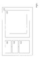
- a fire control panel 100 of a fire detection system is shown, by way of example, in Figure 1 .
- the control panel 100 has a processor 101, which, through a detector interface 102 communicates with one or more detectors (not shown) via a communication link 106. Although the detectors can be connected radially from the detector interface, groups of detectors are normally connected in series on a loop with the ends of the loops meeting at the detector interface 102. In most systems, more than one loop of detectors are connected at the detector interface.
- the processor 101 has a sampler 103, which samples incoming information.
- the control panel 100 also includes a system condition generator 104 and a storage medium 105.
- a loop processor 107 is also located in the control panel 100, between the processor 101 and the detector interface 102.
- the control panel 100 includes a user interface 110. The user interface is shown in more detail in Figure 2 , and comprises a display 114 and local memory 112.
- Each detector in the system is provided with a sensing element, or sensor.
- the sensor is designed to sense a particular parameter which relates to the conditions at the location of the detector and to transmit a detector value indicative of the sensed parameter to the control panel in a sensor signal.
- the parameter that is to be measured is dependent on the specific conditions to be measured at the location of the detector, and the particular use to which the detector is put. For example, if the sensor is an optical smoke detector, it will transmit signals including detector values corresponding to the amount of obscuration caused by smoke at the location of that detector, the percentage of obscuration being the parameter which is an indication of the amount of smoke at that location.
- a temperature sensor would transmit a signal having a detector value indicative of the temperature at the location of the detector. The temperature is the parameter.
- a CO 2 detector will transmit a signal having a detector value indicative of the CO 2 level at the location of the detector. The CO 2 level is the parameter. Of course, other parameters could also be measured.
- One individual detector may be provided with more than one sensing element, and therefore an individual detector can measure more than one parameter at the detector location at the same time generating detector values which are indicative of those parameters.
- the signals include the detector values relating to the parameters that are measured by the sensing elements within the detector and are transmitted along the communications link 106. The signals are received at the detector interface 102.
- the detector interface 102 controls and manages the signals sent to and received from the detectors, and transmits the signals received from the detectors to the loop processor 107.
- the loop processor 107 time-multiplexes the incoming detector values from all of the detectors at high frequency, so that the integrity of the system is known to a resolution of a matter of a few seconds.
- the loop processor passes the data to the processor 101.
- the system condition generator 104 receives and analyses the loop processor output values.
- the system condition generator 104 provides the processor 101 with information relating to the status of the detection system based on the signals received from the detector interface.
- the system condition generated will be a fault condition if a fault has been detected, or an alarm condition if detector values indicate that a parameter detected by a sensor element is outside a normal range, or a normal condition if the system is operating normally with no fire detected.
- the sampler 103 periodically samples the detector values and the system condition from the system condition generator 104.
- the time period between samples and the duration of sampling may be defined by a user on the user interface, and varied depending on the parameter or parameters being sampled, and the specific conditions of the system.
- the period and duration are stored in the storage medium 105 or within the user interface 110, as is mentioned later.
- the processor 101 time-stamps the periodically sampled detector value or values and the system condition information at the time at which the value was sampled. These values and information are stored by the processor 101 in the storage medium 105.
- the detector values and information may be stored at separate locations in the storage medium. In one embodiment of the invention, the values relating to different detectors are stored in separate files in the storage medium.
- the processor 101 is in communication with the user interface 110.
- the user interface 110 has a local user interface processor 112, a local memory 111, a user input 113, and a graphical display 114.
- the user interface processor 112 performs operations relating to the control of the sampler 103 and to the display of the sampled values.
- the user interface processor 112 retrieves the time-stamped detector values from one or more detectors stored in the storage medium 105 on instruction from a user, and stores the information in its local memory 111. The time-stamped detector values may then be displayed graphically on the graphical display 114 without impairing the performance of the processor 101.
- the graphical display 114 is used to display the time-stamped detector information graphically in the form of an X-Y plot, a line graph, or other plot. Values from more than one detector or group of detectors may be displayed concurrently. This allows the user to view specific system characteristics either independently or in relation to each other, which facilitates the analysis of the system's behaviour over time.
- the system condition information may also be indicated on the graphical display 114 of the user interface 110.
- the user input 113 is a keypad in this embodiment, although other user inputs are possible.
- the control panel 100 is accessed by a user, typically a technician, using the user input 113 of the user interface 110.
- the user may configure the control panel 100 to store detector values from one or more of the detectors, or groups of detectors in the storage medium 105.
- the user may define the time period between which the samples are taken, and the time duration over which they are to be taken. For example, the user might define a sample period of one minute with a sample duration of 1000 minutes, for each detector in the system.
- the processor 101 then samples the required detector values of the detectors at one minute intervals from a defined start time selected by the user. The sampling can be made to begin immediately or to be delayed so as to start at a predetermined later time.
- each detector transmits a sensor signal which includes the detector value which is indicative of the parameter being sensed by that detector and this is received by the detector interface 102 and passed to the loop processor 107.
- the sampler 103 samples the detector values from the detectors that have been selected for sampling.
- the sampled values are time-stamped as they are collected and stored in the storage medium 105, with values relating to each detector or group of detectors being stored in a different location on the storage medium 105 if multiple detectors are selected to be sampled.
- the technician later selects some or all of the stored detector values to be displayed using the user interface 110, and they are loaded into the local memory 111.
- the selected detector values can be graphically displayed on the display 114 plotted against time, using the time stamps.
- the graphical representation of the selected values may take the form of a line plot, a histogram or other graphical plot, as discussed above.
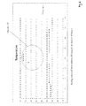
- Figure 3 is an example of a graphical plot showing the temperature detected by a detector on the Y axis against time.
- the user may use the user interface to view data from one or more sensor elements which may be displayed on the same graph, and the user may also make a selection to display a plot of the condition status.
- the user can also view a specific time portion of the sampled data, if analysis of a particular event is required.
- Fig. 3 shows that the temperature at a particular detector on a loop of detectors (Loop A) was elevated for a period in the middle of the range of sampled values, possibly signifying an alarm condition.
- Loop A loop A
- the selected values are streamed from the storage medium and stored there prior to being displayed, so that the user may manipulate or view the display without impairing the main processor 101 of the control panel 100.
- the storage of the values to be graphically displayed in the local memory 111 of the user interface 110 precludes the graphical display from making unnecessary demands on the processor 100, which is required to maintain the integrity of the detection system.
- a fire detection system has been installed in a building, one part of the building being a kitchen, that kitchen will include a fire detector.
- a kitchen has the characteristic of frequently becoming partly filled with smoke as a result of cooking activity, but that smoke is not necessarily indicative of a fire which must be signalled.
- smoke detectors in kitchens tend to lead to frequent false alarms.
- a more appropriate type of detector might be a heat detector since this is more indicative in a kitchen of a fire condition.
- smoke detectors are sometimes inappropriately installed in kitchens.
- a technician is able to arrange for the detector values in the fire detection system to be stored for a period of time, perhaps 24 hours, so that he can then study the values the following day once the sampling period has been completed.
- the values from the smoke detector in the kitchen were significantly increased for a short period of time during the sampling period.
- An example of this might be that shown in Figure 3 in which the value of a particular detector is raised.
- the technician can then investigate the cause of the increase in values from that detector and is likely to notice that a smoke detector has been installed when a temperature detector would have been a better choice. He is then able to take the necessary remedial action by replacing the detector with an appropriate one.
- the processor 101 can be arranged so that its constituent parts are distributed rather than held within a single unit.
- the storage 105 is shown as being part of the processor 104, but the storage 105 could be placed separately.
Landscapes
- Physics & Mathematics (AREA)
- General Physics & Mathematics (AREA)
- Business, Economics & Management (AREA)
- Emergency Management (AREA)
- Engineering & Computer Science (AREA)
- Computer Security & Cryptography (AREA)
- Fire Alarms (AREA)
- Investigating Or Analyzing Materials By The Use Of Fluid Adsorption Or Reactions (AREA)
Applications Claiming Priority (1)
| Application Number | Priority Date | Filing Date | Title |
|---|---|---|---|
| GB1321139.6A GB2520757A (en) | 2013-11-29 | 2013-11-29 | Control panel for a fire detection system |
Publications (2)
| Publication Number | Publication Date |
|---|---|
| EP2879105A1 true EP2879105A1 (de) | 2015-06-03 |
| EP2879105B1 EP2879105B1 (de) | 2018-09-26 |
Family
ID=49979577
Family Applications (1)
| Application Number | Title | Priority Date | Filing Date |
|---|---|---|---|
| EP14195284.6A Active EP2879105B1 (de) | 2013-11-29 | 2014-11-27 | Bedienfeld für ein Feuermeldesystem |
Country Status (2)
| Country | Link |
|---|---|
| EP (1) | EP2879105B1 (de) |
| GB (1) | GB2520757A (de) |
Cited By (3)
| Publication number | Priority date | Publication date | Assignee | Title |
|---|---|---|---|---|
| CN114207683A (zh) * | 2019-05-22 | 2022-03-18 | 泰科消防产品有限合伙公司 | 具有学习模式的火灾检测系统 |
| WO2024209374A1 (en) * | 2023-04-07 | 2024-10-10 | Tyco Fire & Security Gmbh | Fire detection system data device |
| US12592145B2 (en) | 2022-07-01 | 2026-03-31 | Kidde Fire Protection, Llc | Fire detection system testing |
Families Citing this family (1)
| Publication number | Priority date | Publication date | Assignee | Title |
|---|---|---|---|---|
| GB2635569A (en) * | 2023-11-17 | 2025-05-21 | Tyco Fire & Security Gmbh | Data logging in a fire alarm system |
Citations (3)
| Publication number | Priority date | Publication date | Assignee | Title |
|---|---|---|---|---|
| JPH0896265A (ja) * | 1994-09-29 | 1996-04-12 | Hochiki Corp | 火災報知装置 |
| JP2000163669A (ja) * | 1998-11-30 | 2000-06-16 | Hochiki Corp | 火災感知設備における感知情報表示システム |
| US20130024800A1 (en) * | 2011-07-20 | 2013-01-24 | Honeywell International Inc. | System and Method for Playing Back Wireless Fire System History Events |
Family Cites Families (1)
| Publication number | Priority date | Publication date | Assignee | Title |
|---|---|---|---|---|
| US20090045937A1 (en) * | 2007-08-15 | 2009-02-19 | Larry Zimmerman | Hazard and Threat Assessment System |
-
2013
- 2013-11-29 GB GB1321139.6A patent/GB2520757A/en not_active Withdrawn
-
2014
- 2014-11-27 EP EP14195284.6A patent/EP2879105B1/de active Active
Patent Citations (3)
| Publication number | Priority date | Publication date | Assignee | Title |
|---|---|---|---|---|
| JPH0896265A (ja) * | 1994-09-29 | 1996-04-12 | Hochiki Corp | 火災報知装置 |
| JP2000163669A (ja) * | 1998-11-30 | 2000-06-16 | Hochiki Corp | 火災感知設備における感知情報表示システム |
| US20130024800A1 (en) * | 2011-07-20 | 2013-01-24 | Honeywell International Inc. | System and Method for Playing Back Wireless Fire System History Events |
Cited By (4)
| Publication number | Priority date | Publication date | Assignee | Title |
|---|---|---|---|---|
| CN114207683A (zh) * | 2019-05-22 | 2022-03-18 | 泰科消防产品有限合伙公司 | 具有学习模式的火灾检测系统 |
| US12179051B2 (en) | 2019-05-22 | 2024-12-31 | Tyco Fire Products Lp | Fire detection system with a learning mode |
| US12592145B2 (en) | 2022-07-01 | 2026-03-31 | Kidde Fire Protection, Llc | Fire detection system testing |
| WO2024209374A1 (en) * | 2023-04-07 | 2024-10-10 | Tyco Fire & Security Gmbh | Fire detection system data device |
Also Published As
| Publication number | Publication date |
|---|---|
| GB2520757A (en) | 2015-06-03 |
| GB201321139D0 (en) | 2014-01-15 |
| EP2879105B1 (de) | 2018-09-26 |
Similar Documents
| Publication | Publication Date | Title |
|---|---|---|
| KR102290850B1 (ko) | 다중 센서 데이터 수집 전파 장치 및 안전 모니터링 시스템 | |
| RU2517309C2 (ru) | Система и способ оповещения о пожаре и воспламеняющемся газе | |
| EP3859706B1 (de) | Selbstprüfende brandmeldevorrichtung | |
| US8485019B2 (en) | Methods and systems for analysis, reporting and display of environmental data | |
| RU2636007C2 (ru) | Устройство и способ динамического измерения показателя качества среды | |
| US20050246119A1 (en) | Event occurrence graph | |
| EP2879105B1 (de) | Bedienfeld für ein Feuermeldesystem | |
| EP3044769B1 (de) | Verfahren und überwachungszentrale zur überwachung des auftretens eines ereignisses | |
| US9720015B2 (en) | Intelligent visualization in the monitoring of process and/or system variables | |
| KR102237792B1 (ko) | 센스 디바이스 상태 모니터링 장치 | |
| KR20180121389A (ko) | 시설 감시 장치 | |
| JP2009009538A (ja) | 運転状況分析方法および運転状況分析システム | |
| JP6807240B2 (ja) | 送信システム | |
| JP7045200B2 (ja) | 火災検知システム | |
| US12431008B2 (en) | Performing a self-clean of a fire sensing device | |
| KR101701733B1 (ko) | 감시진단기기의 시험 평가 장치 | |
| JP2017098834A (ja) | 集中管理装置および通信障害要因解析方法 | |
| JP2011039676A (ja) | 監視装置及び警報通知方法 | |
| JP2002149234A (ja) | 集中監視装置、集中監視方法、及び記録媒体 | |
| JP7174535B2 (ja) | 火災受信機 | |
| US11676477B2 (en) | Fire alarm system | |
| JP2012023644A (ja) | 監視カメラ、及び監視カメラシステム | |
| CN121409427A (zh) | 一种恒温房温度监控和预警方法、装置、设备及介质 | |
| KR20170126585A (ko) | 데이터 관리 시스템 | |
| CN118200183A (zh) | 异常检测方法、装置、设备及存储介质 |
Legal Events
| Date | Code | Title | Description |
|---|---|---|---|
| PUAI | Public reference made under article 153(3) epc to a published international application that has entered the european phase |
Free format text: ORIGINAL CODE: 0009012 |
|
| 17P | Request for examination filed |
Effective date: 20141127 |
|
| AK | Designated contracting states |
Kind code of ref document: A1 Designated state(s): AL AT BE BG CH CY CZ DE DK EE ES FI FR GB GR HR HU IE IS IT LI LT LU LV MC MK MT NL NO PL PT RO RS SE SI SK SM TR |
|
| AX | Request for extension of the european patent |
Extension state: BA ME |
|
| RIN1 | Information on inventor provided before grant (corrected) |
Inventor name: BRENNER, ANDREAS Inventor name: KULKARNI, PRASAD |
|
| R17P | Request for examination filed (corrected) |
Effective date: 20151203 |
|
| RBV | Designated contracting states (corrected) |
Designated state(s): AL AT BE BG CH CY CZ DE DK EE ES FI FR GB GR HR HU IE IS IT LI LT LU LV MC MK MT NL NO PL PT RO RS SE SI SK SM TR |
|
| RAP1 | Party data changed (applicant data changed or rights of an application transferred) |
Owner name: TYCO FIRE & SECURITY GMBH |
|
| GRAP | Despatch of communication of intention to grant a patent |
Free format text: ORIGINAL CODE: EPIDOSNIGR1 |
|
| STAA | Information on the status of an ep patent application or granted ep patent |
Free format text: STATUS: GRANT OF PATENT IS INTENDED |
|
| INTG | Intention to grant announced |
Effective date: 20180410 |
|
| GRAS | Grant fee paid |
Free format text: ORIGINAL CODE: EPIDOSNIGR3 |
|
| GRAA | (expected) grant |
Free format text: ORIGINAL CODE: 0009210 |
|
| STAA | Information on the status of an ep patent application or granted ep patent |
Free format text: STATUS: THE PATENT HAS BEEN GRANTED |
|
| AK | Designated contracting states |
Kind code of ref document: B1 Designated state(s): AL AT BE BG CH CY CZ DE DK EE ES FI FR GB GR HR HU IE IS IT LI LT LU LV MC MK MT NL NO PL PT RO RS SE SI SK SM TR |
|
| REG | Reference to a national code |
Ref country code: GB Ref legal event code: FG4D |
|
| REG | Reference to a national code |
Ref country code: CH Ref legal event code: EP |
|
| REG | Reference to a national code |
Ref country code: AT Ref legal event code: REF Ref document number: 1046940 Country of ref document: AT Kind code of ref document: T Effective date: 20181015 |
|
| REG | Reference to a national code |
Ref country code: IE Ref legal event code: FG4D |
|
| REG | Reference to a national code |
Ref country code: DE Ref legal event code: R096 Ref document number: 602014032935 Country of ref document: DE |
|
| REG | Reference to a national code |
Ref country code: NL Ref legal event code: MP Effective date: 20180926 |
|
| PG25 | Lapsed in a contracting state [announced via postgrant information from national office to epo] |
Ref country code: LT Free format text: LAPSE BECAUSE OF FAILURE TO SUBMIT A TRANSLATION OF THE DESCRIPTION OR TO PAY THE FEE WITHIN THE PRESCRIBED TIME-LIMIT Effective date: 20180926 Ref country code: RS Free format text: LAPSE BECAUSE OF FAILURE TO SUBMIT A TRANSLATION OF THE DESCRIPTION OR TO PAY THE FEE WITHIN THE PRESCRIBED TIME-LIMIT Effective date: 20180926 Ref country code: SE Free format text: LAPSE BECAUSE OF FAILURE TO SUBMIT A TRANSLATION OF THE DESCRIPTION OR TO PAY THE FEE WITHIN THE PRESCRIBED TIME-LIMIT Effective date: 20180926 Ref country code: GR Free format text: LAPSE BECAUSE OF FAILURE TO SUBMIT A TRANSLATION OF THE DESCRIPTION OR TO PAY THE FEE WITHIN THE PRESCRIBED TIME-LIMIT Effective date: 20181227 Ref country code: FI Free format text: LAPSE BECAUSE OF FAILURE TO SUBMIT A TRANSLATION OF THE DESCRIPTION OR TO PAY THE FEE WITHIN THE PRESCRIBED TIME-LIMIT Effective date: 20180926 Ref country code: NO Free format text: LAPSE BECAUSE OF FAILURE TO SUBMIT A TRANSLATION OF THE DESCRIPTION OR TO PAY THE FEE WITHIN THE PRESCRIBED TIME-LIMIT Effective date: 20181226 Ref country code: BG Free format text: LAPSE BECAUSE OF FAILURE TO SUBMIT A TRANSLATION OF THE DESCRIPTION OR TO PAY THE FEE WITHIN THE PRESCRIBED TIME-LIMIT Effective date: 20181226 |
|
| REG | Reference to a national code |
Ref country code: LT Ref legal event code: MG4D |
|
| PG25 | Lapsed in a contracting state [announced via postgrant information from national office to epo] |
Ref country code: LV Free format text: LAPSE BECAUSE OF FAILURE TO SUBMIT A TRANSLATION OF THE DESCRIPTION OR TO PAY THE FEE WITHIN THE PRESCRIBED TIME-LIMIT Effective date: 20180926 Ref country code: HR Free format text: LAPSE BECAUSE OF FAILURE TO SUBMIT A TRANSLATION OF THE DESCRIPTION OR TO PAY THE FEE WITHIN THE PRESCRIBED TIME-LIMIT Effective date: 20180926 Ref country code: AL Free format text: LAPSE BECAUSE OF FAILURE TO SUBMIT A TRANSLATION OF THE DESCRIPTION OR TO PAY THE FEE WITHIN THE PRESCRIBED TIME-LIMIT Effective date: 20180926 |
|
| REG | Reference to a national code |
Ref country code: AT Ref legal event code: MK05 Ref document number: 1046940 Country of ref document: AT Kind code of ref document: T Effective date: 20180926 |
|
| PG25 | Lapsed in a contracting state [announced via postgrant information from national office to epo] |
Ref country code: IT Free format text: LAPSE BECAUSE OF FAILURE TO SUBMIT A TRANSLATION OF THE DESCRIPTION OR TO PAY THE FEE WITHIN THE PRESCRIBED TIME-LIMIT Effective date: 20180926 Ref country code: ES Free format text: LAPSE BECAUSE OF FAILURE TO SUBMIT A TRANSLATION OF THE DESCRIPTION OR TO PAY THE FEE WITHIN THE PRESCRIBED TIME-LIMIT Effective date: 20180926 Ref country code: RO Free format text: LAPSE BECAUSE OF FAILURE TO SUBMIT A TRANSLATION OF THE DESCRIPTION OR TO PAY THE FEE WITHIN THE PRESCRIBED TIME-LIMIT Effective date: 20180926 Ref country code: NL Free format text: LAPSE BECAUSE OF FAILURE TO SUBMIT A TRANSLATION OF THE DESCRIPTION OR TO PAY THE FEE WITHIN THE PRESCRIBED TIME-LIMIT Effective date: 20180926 Ref country code: CZ Free format text: LAPSE BECAUSE OF FAILURE TO SUBMIT A TRANSLATION OF THE DESCRIPTION OR TO PAY THE FEE WITHIN THE PRESCRIBED TIME-LIMIT Effective date: 20180926 Ref country code: PL Free format text: LAPSE BECAUSE OF FAILURE TO SUBMIT A TRANSLATION OF THE DESCRIPTION OR TO PAY THE FEE WITHIN THE PRESCRIBED TIME-LIMIT Effective date: 20180926 Ref country code: AT Free format text: LAPSE BECAUSE OF FAILURE TO SUBMIT A TRANSLATION OF THE DESCRIPTION OR TO PAY THE FEE WITHIN THE PRESCRIBED TIME-LIMIT Effective date: 20180926 Ref country code: EE Free format text: LAPSE BECAUSE OF FAILURE TO SUBMIT A TRANSLATION OF THE DESCRIPTION OR TO PAY THE FEE WITHIN THE PRESCRIBED TIME-LIMIT Effective date: 20180926 Ref country code: IS Free format text: LAPSE BECAUSE OF FAILURE TO SUBMIT A TRANSLATION OF THE DESCRIPTION OR TO PAY THE FEE WITHIN THE PRESCRIBED TIME-LIMIT Effective date: 20190126 |
|
| PG25 | Lapsed in a contracting state [announced via postgrant information from national office to epo] |
Ref country code: SK Free format text: LAPSE BECAUSE OF FAILURE TO SUBMIT A TRANSLATION OF THE DESCRIPTION OR TO PAY THE FEE WITHIN THE PRESCRIBED TIME-LIMIT Effective date: 20180926 Ref country code: PT Free format text: LAPSE BECAUSE OF FAILURE TO SUBMIT A TRANSLATION OF THE DESCRIPTION OR TO PAY THE FEE WITHIN THE PRESCRIBED TIME-LIMIT Effective date: 20190126 Ref country code: SM Free format text: LAPSE BECAUSE OF FAILURE TO SUBMIT A TRANSLATION OF THE DESCRIPTION OR TO PAY THE FEE WITHIN THE PRESCRIBED TIME-LIMIT Effective date: 20180926 |
|
| REG | Reference to a national code |
Ref country code: DE Ref legal event code: R097 Ref document number: 602014032935 Country of ref document: DE |
|
| REG | Reference to a national code |
Ref country code: CH Ref legal event code: PL |
|
| PG25 | Lapsed in a contracting state [announced via postgrant information from national office to epo] |
Ref country code: LU Free format text: LAPSE BECAUSE OF NON-PAYMENT OF DUE FEES Effective date: 20181127 Ref country code: MC Free format text: LAPSE BECAUSE OF FAILURE TO SUBMIT A TRANSLATION OF THE DESCRIPTION OR TO PAY THE FEE WITHIN THE PRESCRIBED TIME-LIMIT Effective date: 20180926 Ref country code: DK Free format text: LAPSE BECAUSE OF FAILURE TO SUBMIT A TRANSLATION OF THE DESCRIPTION OR TO PAY THE FEE WITHIN THE PRESCRIBED TIME-LIMIT Effective date: 20180926 |
|
| PLBE | No opposition filed within time limit |
Free format text: ORIGINAL CODE: 0009261 |
|
| STAA | Information on the status of an ep patent application or granted ep patent |
Free format text: STATUS: NO OPPOSITION FILED WITHIN TIME LIMIT |
|
| REG | Reference to a national code |
Ref country code: BE Ref legal event code: MM Effective date: 20181130 |
|
| REG | Reference to a national code |
Ref country code: IE Ref legal event code: MM4A |
|
| PG25 | Lapsed in a contracting state [announced via postgrant information from national office to epo] |
Ref country code: CH Free format text: LAPSE BECAUSE OF NON-PAYMENT OF DUE FEES Effective date: 20181130 Ref country code: LI Free format text: LAPSE BECAUSE OF NON-PAYMENT OF DUE FEES Effective date: 20181130 |
|
| 26N | No opposition filed |
Effective date: 20190627 |
|
| PG25 | Lapsed in a contracting state [announced via postgrant information from national office to epo] |
Ref country code: IE Free format text: LAPSE BECAUSE OF NON-PAYMENT OF DUE FEES Effective date: 20181127 Ref country code: SI Free format text: LAPSE BECAUSE OF FAILURE TO SUBMIT A TRANSLATION OF THE DESCRIPTION OR TO PAY THE FEE WITHIN THE PRESCRIBED TIME-LIMIT Effective date: 20180926 |
|
| PG25 | Lapsed in a contracting state [announced via postgrant information from national office to epo] |
Ref country code: BE Free format text: LAPSE BECAUSE OF NON-PAYMENT OF DUE FEES Effective date: 20181130 |
|
| PG25 | Lapsed in a contracting state [announced via postgrant information from national office to epo] |
Ref country code: MT Free format text: LAPSE BECAUSE OF NON-PAYMENT OF DUE FEES Effective date: 20181127 |
|
| PG25 | Lapsed in a contracting state [announced via postgrant information from national office to epo] |
Ref country code: TR Free format text: LAPSE BECAUSE OF FAILURE TO SUBMIT A TRANSLATION OF THE DESCRIPTION OR TO PAY THE FEE WITHIN THE PRESCRIBED TIME-LIMIT Effective date: 20180926 |
|
| PG25 | Lapsed in a contracting state [announced via postgrant information from national office to epo] |
Ref country code: HU Free format text: LAPSE BECAUSE OF FAILURE TO SUBMIT A TRANSLATION OF THE DESCRIPTION OR TO PAY THE FEE WITHIN THE PRESCRIBED TIME-LIMIT; INVALID AB INITIO Effective date: 20141127 Ref country code: CY Free format text: LAPSE BECAUSE OF FAILURE TO SUBMIT A TRANSLATION OF THE DESCRIPTION OR TO PAY THE FEE WITHIN THE PRESCRIBED TIME-LIMIT Effective date: 20180926 Ref country code: MK Free format text: LAPSE BECAUSE OF NON-PAYMENT OF DUE FEES Effective date: 20180926 |
|
| REG | Reference to a national code |
Ref country code: GB Ref legal event code: 732E Free format text: REGISTERED BETWEEN 20201203 AND 20201209 |
|
| PGFP | Annual fee paid to national office [announced via postgrant information from national office to epo] |
Ref country code: DE Payment date: 20251126 Year of fee payment: 12 |
|
| PGFP | Annual fee paid to national office [announced via postgrant information from national office to epo] |
Ref country code: GB Payment date: 20251125 Year of fee payment: 12 |
|
| PGFP | Annual fee paid to national office [announced via postgrant information from national office to epo] |
Ref country code: FR Payment date: 20251125 Year of fee payment: 12 |