EP2879265B1 - Unité de bobine et un appareil permettant de détecter des corps étrangers - Google Patents
Unité de bobine et un appareil permettant de détecter des corps étrangers Download PDFInfo
- Publication number
- EP2879265B1 EP2879265B1 EP14195246.5A EP14195246A EP2879265B1 EP 2879265 B1 EP2879265 B1 EP 2879265B1 EP 14195246 A EP14195246 A EP 14195246A EP 2879265 B1 EP2879265 B1 EP 2879265B1
- Authority
- EP
- European Patent Office
- Prior art keywords
- resonators
- foreign matter
- coil
- detecting
- power feeding
- Prior art date
- Legal status (The legal status is an assumption and is not a legal conclusion. Google has not performed a legal analysis and makes no representation as to the accuracy of the status listed.)
- Active
Links
Images



Classifications
-
- B—PERFORMING OPERATIONS; TRANSPORTING
- B60—VEHICLES IN GENERAL
- B60L—PROPULSION OF ELECTRICALLY-PROPELLED VEHICLES; SUPPLYING ELECTRIC POWER FOR AUXILIARY EQUIPMENT OF ELECTRICALLY-PROPELLED VEHICLES; ELECTRODYNAMIC BRAKE SYSTEMS FOR VEHICLES IN GENERAL; MAGNETIC SUSPENSION OR LEVITATION FOR VEHICLES; MONITORING OPERATING VARIABLES OF ELECTRICALLY-PROPELLED VEHICLES; ELECTRIC SAFETY DEVICES FOR ELECTRICALLY-PROPELLED VEHICLES
- B60L53/00—Methods of charging batteries, specially adapted for electric vehicles; Charging stations or on-board charging equipment therefor; Exchange of energy storage elements in electric vehicles
- B60L53/10—Methods of charging batteries, specially adapted for electric vehicles; Charging stations or on-board charging equipment therefor; Exchange of energy storage elements in electric vehicles characterised by the energy transfer between the charging station and the vehicle
- B60L53/12—Inductive energy transfer
- B60L53/124—Detection or removal of foreign bodies
-
- H02J5/005—
-
- G—PHYSICS
- G01—MEASURING; TESTING
- G01N—INVESTIGATING OR ANALYSING MATERIALS BY DETERMINING THEIR CHEMICAL OR PHYSICAL PROPERTIES
- G01N27/00—Investigating or analysing materials by the use of electric, electrochemical, or magnetic means
- G01N27/02—Investigating or analysing materials by the use of electric, electrochemical, or magnetic means by investigating impedance
- G01N27/023—Investigating or analysing materials by the use of electric, electrochemical, or magnetic means by investigating impedance where the material is placed in the field of a coil
- G01N27/025—Investigating or analysing materials by the use of electric, electrochemical, or magnetic means by investigating impedance where the material is placed in the field of a coil a current being generated within the material by induction
-
- G—PHYSICS
- G01—MEASURING; TESTING
- G01V—GEOPHYSICS; GRAVITATIONAL MEASUREMENTS; DETECTING MASSES OR OBJECTS; TAGS
- G01V3/00—Electric or magnetic prospecting or detecting; Measuring magnetic field characteristics of the earth, e.g. declination, deviation
- G01V3/08—Electric or magnetic prospecting or detecting; Measuring magnetic field characteristics of the earth, e.g. declination, deviation operating with magnetic or electric fields produced or modified by objects or geological structures or by detecting devices
- G01V3/10—Electric or magnetic prospecting or detecting; Measuring magnetic field characteristics of the earth, e.g. declination, deviation operating with magnetic or electric fields produced or modified by objects or geological structures or by detecting devices using induction coils
-
- H—ELECTRICITY
- H01—ELECTRIC ELEMENTS
- H01F—MAGNETS; INDUCTANCES; TRANSFORMERS; SELECTION OF MATERIALS FOR THEIR MAGNETIC PROPERTIES
- H01F38/00—Adaptations of transformers or inductances for specific applications or functions
- H01F38/14—Inductive couplings
-
- H—ELECTRICITY
- H02—GENERATION; CONVERSION OR DISTRIBUTION OF ELECTRIC POWER
- H02J—ELECTRIC POWER NETWORKS; CIRCUIT ARRANGEMENTS OR SYSTEMS FOR SUPPLYING OR DISTRIBUTING ELECTRIC POWER; SYSTEMS FOR STORING ELECTRIC ENERGY
- H02J50/00—Circuit arrangements or systems for wireless supply or distribution of electric power
- H02J50/10—Circuit arrangements or systems for wireless supply or distribution of electric power using inductive coupling
- H02J50/12—Circuit arrangements or systems for wireless supply or distribution of electric power using inductive coupling of the resonant type
-
- H—ELECTRICITY
- H02—GENERATION; CONVERSION OR DISTRIBUTION OF ELECTRIC POWER
- H02J—ELECTRIC POWER NETWORKS; CIRCUIT ARRANGEMENTS OR SYSTEMS FOR SUPPLYING OR DISTRIBUTING ELECTRIC POWER; SYSTEMS FOR STORING ELECTRIC ENERGY
- H02J50/00—Circuit arrangements or systems for wireless supply or distribution of electric power
- H02J50/60—Circuit arrangements or systems for wireless supply or distribution of electric power responsive to the presence of foreign objects, e.g. detection of living beings
-
- H02J7/025—
-
- B—PERFORMING OPERATIONS; TRANSPORTING
- B60—VEHICLES IN GENERAL
- B60L—PROPULSION OF ELECTRICALLY-PROPELLED VEHICLES; SUPPLYING ELECTRIC POWER FOR AUXILIARY EQUIPMENT OF ELECTRICALLY-PROPELLED VEHICLES; ELECTRODYNAMIC BRAKE SYSTEMS FOR VEHICLES IN GENERAL; MAGNETIC SUSPENSION OR LEVITATION FOR VEHICLES; MONITORING OPERATING VARIABLES OF ELECTRICALLY-PROPELLED VEHICLES; ELECTRIC SAFETY DEVICES FOR ELECTRICALLY-PROPELLED VEHICLES
- B60L2270/00—Problem solutions or means not otherwise provided for
- B60L2270/10—Emission reduction
- B60L2270/14—Emission reduction of noise
- B60L2270/147—Emission reduction of noise electro magnetic [EMI]
-
- Y—GENERAL TAGGING OF NEW TECHNOLOGICAL DEVELOPMENTS; GENERAL TAGGING OF CROSS-SECTIONAL TECHNOLOGIES SPANNING OVER SEVERAL SECTIONS OF THE IPC; TECHNICAL SUBJECTS COVERED BY FORMER USPC CROSS-REFERENCE ART COLLECTIONS [XRACs] AND DIGESTS
- Y02—TECHNOLOGIES OR APPLICATIONS FOR MITIGATION OR ADAPTATION AGAINST CLIMATE CHANGE
- Y02T—CLIMATE CHANGE MITIGATION TECHNOLOGIES RELATED TO TRANSPORTATION
- Y02T10/00—Road transport of goods or passengers
- Y02T10/60—Other road transportation technologies with climate change mitigation effect
- Y02T10/70—Energy storage systems for electromobility, e.g. batteries
-
- Y—GENERAL TAGGING OF NEW TECHNOLOGICAL DEVELOPMENTS; GENERAL TAGGING OF CROSS-SECTIONAL TECHNOLOGIES SPANNING OVER SEVERAL SECTIONS OF THE IPC; TECHNICAL SUBJECTS COVERED BY FORMER USPC CROSS-REFERENCE ART COLLECTIONS [XRACs] AND DIGESTS
- Y02—TECHNOLOGIES OR APPLICATIONS FOR MITIGATION OR ADAPTATION AGAINST CLIMATE CHANGE
- Y02T—CLIMATE CHANGE MITIGATION TECHNOLOGIES RELATED TO TRANSPORTATION
- Y02T10/00—Road transport of goods or passengers
- Y02T10/60—Other road transportation technologies with climate change mitigation effect
- Y02T10/7072—Electromobility specific charging systems or methods for batteries, ultracapacitors, supercapacitors or double-layer capacitors
-
- Y—GENERAL TAGGING OF NEW TECHNOLOGICAL DEVELOPMENTS; GENERAL TAGGING OF CROSS-SECTIONAL TECHNOLOGIES SPANNING OVER SEVERAL SECTIONS OF THE IPC; TECHNICAL SUBJECTS COVERED BY FORMER USPC CROSS-REFERENCE ART COLLECTIONS [XRACs] AND DIGESTS
- Y02—TECHNOLOGIES OR APPLICATIONS FOR MITIGATION OR ADAPTATION AGAINST CLIMATE CHANGE
- Y02T—CLIMATE CHANGE MITIGATION TECHNOLOGIES RELATED TO TRANSPORTATION
- Y02T90/00—Enabling technologies or technologies with a potential or indirect contribution to GHG emissions mitigation
- Y02T90/10—Technologies relating to charging of electric vehicles
- Y02T90/12—Electric charging stations
-
- Y—GENERAL TAGGING OF NEW TECHNOLOGICAL DEVELOPMENTS; GENERAL TAGGING OF CROSS-SECTIONAL TECHNOLOGIES SPANNING OVER SEVERAL SECTIONS OF THE IPC; TECHNICAL SUBJECTS COVERED BY FORMER USPC CROSS-REFERENCE ART COLLECTIONS [XRACs] AND DIGESTS
- Y02—TECHNOLOGIES OR APPLICATIONS FOR MITIGATION OR ADAPTATION AGAINST CLIMATE CHANGE
- Y02T—CLIMATE CHANGE MITIGATION TECHNOLOGIES RELATED TO TRANSPORTATION
- Y02T90/00—Enabling technologies or technologies with a potential or indirect contribution to GHG emissions mitigation
- Y02T90/10—Technologies relating to charging of electric vehicles
- Y02T90/14—Plug-in electric vehicles
Definitions
- the present invention relates to a coil unit and an apparatus for detecting foreign matter.
- the contactless power transmission in which the power is supplied without using a power cord is attracting attentions.
- the conventional contactless power transmission is mainly the type based on the electromagnetic induction. It is expected that this technique can be applied to various fields.
- an electric vehicle is provided with a power receiving coil at its bottom part (power receiving side) and a high power (for example, several kilowatt to several tens of kilowatt) is transmitted in a contactless manner from a power feeding coil on the ground (power feeding side). If the contactless power transmission can be utilized, then the power can be transmitted without mechanically coupling power feeding side to power receiving side.
- a high power for example, several kilowatt to several tens of kilowatt
- Patent Document 1 has suggested a detecting apparatus with a detecting part.
- the detecting part is provided with one or a plurality of magnetic coupling elements which is/are composed of a plurality of coils. It measures the electric parameters related to the magnetic coupling element(s) or a circuit containing at least the magnetic coupling element(s) and then determines whether a foreign matter that may generate heat due to the magnetic flux is present based on the changes of these electric parameters.
- Patent Document 1 JP-A-2013-192390
- a plurality of detecting coils are disposed without gaps to eliminate the dead area where the foreign metal cannot be detected, wherein the plurality of detecting coils are connected to the capacitor for resonance and resonates with a given frequency.
- several resonance frequencies are present for each detecting coil (magnetic coupling element) so that the measurement becomes difficult.
- the Q value of each detecting coil is significantly lowered and the measuring accuracy becomes worse.
- a problem is there that the accuracy in detecting the foreign metal is deteriorated.
- the present invention aims to provide a coil unit with a better accuracy in detecting foreign matter and an apparatus for detecting foreign matter with a better accuracy in detecting foreign matter when the power is transmitted in a contactless manner.
- the coil unit of the present invention is characterized in that it is a coil unit used for contactless power transmission from power feeding side to power receiving side.
- the coil unit is provided with a coil for power transmission and an apparatus for detecting foreign matter.
- the apparatus for detecting foreign matter is provided with a plurality of resonators having a resonance coil and a resonance capacitor and also an excitation coil which excites the plurality of resonators.
- the plurality of resonators are disposed in rows and columns so as to cover at least an area interlinking with a magnetic flux generated by the coil for power transmission.
- the excitation coil makes resonators adjacent with each other in a row direction and a column direction among a plurality of resonators to generate an alternating magnetic field with resonance frequencies different from each other within a frequency band in which the coil for power transmission is not excited.
- the excitation coil makes the resonators adjacent with each other in the row direction and the column direction among the plurality of resonators to generate the alternating magnetic field with resonance frequencies different from each other within a frequency band in which the coil for power transmission is not excited.
- each resonator can be prevented from influencing each other.
- each resonator is prevented from generating multiple resonance frequencies so that the decrease of Q value will be inhibited.
- the accuracy in detecting metals will be improved when power is transmitted in a contactless manner.
- the excitation coil makes one resonator and the resonators which is disposed surrounding it among the plurality of resonators, to generate an alternating magnetic field with resonance frequencies different from each other.
- each resonator can be further prevented from influencing each other. So each resonator is practically prevented from generating multiple resonance frequencies, the decrease of Q value will be further inhibited. Therefore, the accuracy in detecting metals will be further improved when power is transmitted in a contactless manner.
- the apparatus for detecting foreign matter is further provided with a plurality of detecting coils and each of the plurality of detecting coils is disposed so as to be magnetically coupled to each resonator of the plurality of resonators.
- the Q values of the plurality of resonators can be indirectly measured without connecting a means for Q value measurement directly to the plurality of resonators, the Q values of the plurality of resonators can be further prevented from decreasing without changing the resonance frequencies of the plurality of resonators.
- the apparatus for detecting foreign matter is characterized in that it is an apparatus for detecting foreign matter for a detection of foreign matter and is provided with a plurality of resonators having a resonance coil and a resonance capacitor and also an excitation coil which excites the plurality of resonators.
- the plurality of resonators are placed in rows and columns in an in-plane direction.
- the excitation coil makes resonators adjacent with each other in a row direction and a column direction among the plurality of resonators, to generate an alternating magnetic field with resonance frequencies different from each other of a frequency band.
- the excitation coil makes the resonators adjacent in the row direction and the column direction to generate the alternating magnetic field among the plurality of resonators with resonance frequencies different from each other of a frequency band.
- each resonator can be prevented from influencing each other.
- each resonator is prevented from generating multiple resonance frequencies so that the decrease of Q value will be inhibited. As a result, the accuracy in detecting metals will be improved.
- a coil unit with an improved accuracy in detecting foreign matter and an apparatus for detecting foreign matter with an improved accuracy in detecting foreign matter when power is transmitted in a contactless manner can be provided.
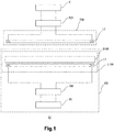
- FIG. 1 is a schematic view showing the apparatus, to which the coil unit of the preferable embodiments is applied, for contactless power transmission together with the load.
- the coil unit of the present invention can be used as any one of a power feeding coil unit in a power feeding apparatus and a power receiving coil unit in a power receiving apparatus.
- the coil unit of the present invention will be described in examples in which the coil unit is applied as the power feeding coil unit in a power feeding apparatus.
- the apparatus S1 for contactless power transmission is provided with a power feeding apparatus 100 and a power receiving apparatus 200.
- the apparatus S1 for contactless power transmission is described in an example in which the apparatus S1 is used as a power feeding apparatus for supplying power to a moving object such as an electric vehicle.
- the power feeding apparatus 100 is provided with a voltage source VG, a power conversion circuit INV and a power feeding coil unit L100.
- the voltage source VG feeds a direct current to the power conversion circuit INV to be described later.
- the voltage source VG is not particularly restricted as long as it outputs a direct current.
- the power supply can be a direct-current power supply from a rectified and stabilized commercial alternating-current power supply, a secondary battery, a direct-current power supply with power generated via solar energy, or a switching power supply such a switching converter.
- the power conversion circuit INV converts the direct current supplied from the voltage source VG to an alternating current and then supplies the alternating voltage to the power feeding coil unit L100 to be described later.
- the power conversion circuit INV functions as an inverter.
- the power conversion circuit INV can be composed of, for example, a switching circuit with multiple switching elements being bridge connected (not shown in the figures).
- the switching element forming the switching circuit can be, for example, an element such as MOS-FET (metal oxide semiconductor-field effect transistor), IBGT (insulated gate bipolar transistor) or the like.
- the power feeding coil unit L100 functions as a power feeding part for transmitting the alternating current in a contactless manner to the power receiving apparatus 200, which is to be described later.
- the power feeding coil unit L100 is disposed below the ground or at somewhere near the ground. Further, the specific structure of the power feeding coil unit L100 will be described below.
- the power receiving apparatus 200 is provided with a power receiving coil L2 and a rectification circuit REC.
- the power receiving apparatus 200 is provided on the moving object.
- the moving object provided with the power receiving apparatus 200 can be an electric vehicle or a hybrid vehicle utilizing the power from a secondary battery.
- the power receiving coil L2 functions as a power receiving part for receiving the alternating power supplied from the power feeding coil unit L100 in a contactless manner.
- the power receiving coil L2 is disposed at the bottom part of the electric vehicle.
- the rectification circuit REC rectifies the alternating current received by the power receiving coil L2 to a direct current and then outputs the direct current to a load R.
- the rectification circuit REC is composed of, for example, a bridge diode and a capacitor for voltage stabilization (both not shown in the figures).
- the alternating voltage output from the power receiving coil L2 is subjected to a full-wave rectification by a bridge diode, and then the resultant voltage is stabilized by a capacitor for voltage stabilization.
- the load R is composed of a charger (not shown) and a battery (not shown) provided in the moving object.
- the charger functions to control the charging process by charging the battery with a constant current-constant voltage (CCCV) by a direct current rectified by the rectification circuit REC.
- the battery is not particularly restricted as long as it is capable of saving power.
- the battery can be a secondary battery (a lithium ion battery, a lithium polymer battery, a Nickel-Metal Hydride battery or the like) or a capacity element (an electrical double-layered capacitor or the like).
- the apparatus S1 for contactless power transmission can be provided with which the power is transmitted in a contactless manner from the power feeding coil unit L100 in the power feeding apparatus 100 to the power receiving coil L2 in the power receiving apparatus 200.
- Figure 2 is a schematic constitutional view showing the power feeding coil unit of the first embodiment viewed from the top in the present invention.
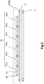
- Figure 3 is a schematic end face view showing the cutting section of the power feeding coil unit along the I-I line in Figure 2 .
- the power feeding coil unit L100 is provided with a power feeding coil L1 (the coil for power transmission), an apparatus D100 for detecting foreign matter, a signal generator SG and a frequency response analyzer A100.
- the power feeding coil L1 is substantially square and is formed by, for example, winding a litz wire into several turns to several dozen of turns, wherein the litz wire is obtained by twisting about 2000 insulated ⁇ 0.1 (mm) copper lines.
- the power feeding coil L1 is one with an in-plane spiral structure.
- the terminal A at the end where the winding starts and the terminal B at the end where the winding ends are connected to the power conversion circuit INV.
- the power feeding coil L1 functions as one for transmitting power in a contactless manner to the power receiving coil L2.
- the driving frequency of the alternating voltage fed to the power feeding coil L1 is set to be, for example, 20 [kHz] to 200 [kHz].
- the apparatus D100 for detecting foreign matter is disposed at one side of the power feeding coil L1 which faces the power receiving coil L2. That is, the apparatus D100 for detecting foreign matter is disposed between the power feeding coil L1 (power feeding side) and the power receiving coil L2 (power receiving side).
- the apparatus D100 for detecting foreign matter is composed of copper-clad multilayered substrates and is provided with a plurality of resonators R1 and an excitation coils E1.
- the plurality of resonators R1 are disposed in rows and columns in order to at least cover the area interlinking with the magnetic flux generated by the power feeding coil L1.
- the plurality of resonators R1 are placed in rows and columns in the in-plane direction as shown in Fig.2 . More specifically, the plurality of resonators R1 are disposed to cover the area defined by the wound wires of the power feeding coil L1.
- 36 resonators R1 are placed in 6 rows ⁇ 6 columns. That is, the area where the plurality of resonators R1 are disposed becomes the area for metal detection.
- the plurality of resonators R1 are each formed by each resonance coil M1 and each resonance capacitor C1.
- the resonance coil M1 presents to be substantially square and is formed by, for example, pattern printing 4 turns of coils on a layer of the copper-clad multilayered substrate at the side of the power receiving coil L2 in a direction in which the power feeding coil L1 faces the power receiving coil L2.
- the resonance capacitor C1 and the resonance coil M1 are connected in series to form a resonance circuit.
- the resonance capacitor C1 can be, for example, a stacked ceramic capacitor, and the electrostatic capacity of the resonance capacitor C1 is set to be several hundreds of picofarad to several thousands of picofarads.
- each resonator R1 can be made as a substantial square with a size of 10 mm ⁇ 10 mm.
- the plurality of resonators R1 can also be disposed in rows and columns to cover a wider area than that defined by the wound wire of the power feeding coil L1. In that case, not only the foreign matter on the power feeding coil L1 but also those surrounding the power feeding coil L1 can be detected.
- the area where the plurality of resonators R1 are disposed in rows and columns can cover at least the area interlinking with the magnetic flux generated by the power feeding coil L1, it can be set at will.
- the plurality of resonators R1 with the structure mentioned above are composed of two kinds of resonators, i.e., the resonator R1a and the resonator R1b.
- each of the resonator R1a and the resonator R1b has a single resonance frequency of the frequency band in which the power feeding coil L1 will not be excited, and the two single resonance frequency are respectively set as the resonance frequency fr1 and fr2 which are different from each other.
- the resonance frequency fr1 of the resonator R1a is set to be 3000 [kHz] and the resonance frequency fr2 of the resonator R1b is set to be 6000 [kHz].
- the resonators R1a and the resonators R1b are alternatively disposed to be adjacent in the row direction and the column direction.
- the resonators R1a are not adjacent to each other in the row direction and the column direction and the resonators R1b are not adjacent to each other in the row direction and the column direction.
- the mutual inductance will be changed and several resonance frequencies will generate because resonance coils of the adjacent resonators will be magnetically coupled with each other. Also, the Q value of the resonance coil in each resonator will significantly decrease.
- the resonance frequency fr1 of the resonator R1a and the resonance frequency fr2 of the resonator R1b which are adjacent to each other in the row direction and the column direction, is set to be different, so no interaction is present near the resonance frequency fr1 of the resonator R1a or near the resonance frequency fr2 of the resonator R1b and the resonator R1a and the resonator R1b respectively have a single resonance frequency.
- the Q value of the resonance coil M1 of the resonator R1a and the Q value of the resonance coil M1 of the resonator R1b can be prevented from decreasing.
- the resonator R1a and the resonator R1b are not disposed to be adjacent in the row direction and the column direction in the whole area for metal detection.
- the resonators R1a can be placed to be adjacent in the row direction or the column direction in part of the area for metal detection, so do the resonators R1b.
- the excitation coil E1 is substantially square and is formed by, for example, pattern printing 3 turns of coils on a layer of the copper-clad multilayered substrate at the side of the power receiving coil L1 in a direction in which the power feeding coil L1 faces the power receiving coil L2.
- the pattern of the excitation coil E1 is formed outside the area defined by the wound wire of the power feeding coil L1.
- the end where the pattern of the excitation coil E1 starts i.e., the terminal C
- the end where the pattern ends i.e., the terminal D
- the excitation coil E1 is capable of receiving the sine wave signals output from the signal generator SG and is then excited to generate a magnetic field.
- the resonance coils M1 of the plurality of resonators R1 will be excited by the magnetic field generated by the excitation coil E1.
- the signal generator SG provides two sine wave signals of different frequencies alternatively to the excitation coil E1 with a certain interval (such as every 100 ms).
- the frequency of each of the two sine wave signals is set to be the same with the resonance frequency fr1 of the resonator R1a or the resonance frequency fr2 of the resonator R1b. That is, in the two sine wave signals, one of the sine wave signal was set to have a frequency of 3000 [kHz] which is the same as the resonance frequency fr1 of the resonator R1a, and the other one is set to have a frequency of 6000 [kHz] which is the same as the resonance frequency fr2 of the resonator R1b.
- the excitation coil E1 receives the sine wave signal output from the signal generator SG and is then excited to generate a magnetic field. An electromotive force is generated via this magnetic field so that the current flows to the resonance coils M1 of the plurality of resonators R1.
- the resonance frequency of the resonator R1a is set to be 3000 [kHz], so the resonator R1a comes into the resonance state and a resonance current flows only when the signal generator SG outputs a sine wave signal of 3000 [kHz].
- the resonance frequency of the resonator R1b is set to be 6000 [kHz]
- the resonator R1b comes into the resonance state and a resonance current flows only when the signal generator SG outputs a sine wave signal of 6000 [kHz].
- the frequencies of these two sine wave signals with which the signal generator SG excites the excitation coil E1 are set as a high frequency having an order of magnitude different from that of the driving frequency of the power feeding coil L1.
- the frequencies of these two sine wave signals output by the signal generator SG with which the excitation coil E1 is excited are set to be within a frequency band in which the power feeding coil L1 is not excited.
- the excitation coil E1 makes the resonator R1a and the resonator R1b adjacent in the row direction and the column direction among the plurality of resonators R1 to generate the alternating magnetic field with different resonance frequencies from each other in a frequency band in which the power feeding coil L1 inside is not excited.
- the resonance coils M1 of the plurality of resonators R1 are excited by a very strong magnetic field for power transmission generated by the power feeding coil L1. In this way, a large current will flow to the plurality of resonators R1 and concerns rise that the resonators R1 may be destroyed.
- the frequencies of the two sine wave signals output by the signal generator SG is set to be a high frequency with a different order of magnitude from the driving frequency of the power feeding coil L1 (i.e., the frequency band in which the power feeding coil L1 is not excited), thus, the plurality of resonators R1 has a high impedance with respect to the strong magnetic field for power transmission generated by the power feeding coil L1 so that no current flows. Further, the plurality of resonators R1 are only syntonized with frequencies of the two sine wave signals output by the signal generator SG with which the excitation coil E1is excited, so that the plurality of resonators R1 is excited and a current flows.
- the two frequencies output by the signal generator SG with which the excitation coil E1 is excited is set to be one with the order of magnitude being higher than that of the driving frequency of the power feeding coil L1.
- these two frequencies are not limited thereto and can be also set as one with the order of magnitude being lower than that of the driving frequency of the power feeding coil L1.
- the resonance frequency fr1 of the resonator R1a and the resonance frequency fr2 of the resonator R1b are also set as ones with the order of magnitude being lower than that of the driving frequency of the power feeding coil L1.
- the two frequencies output by the signal generator SG with which the excitation coil E1 is excited are set to within a frequency band in which the power feeding coil L1 is not excited.
- the frequency response analyzer A100 is connected to two terminals in the resonance capacitor C1 of the plurality of resonators R1. If the frequency response analyzer A100 is used, the impedance value and the Q value can be measured in the plurality of resonators R1. In the present embodiment, the frequency response analyzer A100 is used to detect the foreign metals. Specifically, the impedance value and the Q value at the resonance frequency of the resonator R1 when no foreign metal is present are memorized. Then, the impedance values and Q values measured by the frequency response analyzer A100 are compared and the presence of the foreign metals can be determined based on the changes of these values.
- the impedance value as measured by the frequency response analyzer A100 will increase and the Q value will decrease. If thresholds capable of determining whether a foreign metal are present or not is predetermined with respect to the impedance value and the Q value, then the presence of a foreign metal can be determined based on these thresholds. In this respect, if the frequency response analyzer A100 is used to measure the electric properties of the plurality of resonators R1 (i.e., the impedance value and the Q value), it is easy to detect the foreign metals.
- the excitation coil E1 makes the resonators R1a and R1b which are adjacent in the row direction and the column direction among the plurality of resonators R1 to generate an alternating magnetic field with resonance frequencies different from each other within a frequency band in which the power feeding coil L1 is not excited.
- each resonator R1a/R1b can be prevented from influencing each other even if the plurality of resonators R1 are disposed without gaps in the area for metal detection, each resonator R1a/R1b can be prevented from generating multiple resonance frequencies and the decrease of the Q value can be inhibited as well.
- the accuracy in detecting foreign matter can be improved when the power is transmitted in a contactless manner.
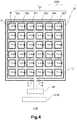
- Figure 4 is a schematic constitutional view showing the power feeding coil unit of the second embodiment viewed from the top in the present invention.
- the power feeding coil unit L200 is provided with a power feeding coil L1, an apparatus D200 for detecting foreign matter, a signal generator SG2 and a frequency response analyzer A100.
- the structures of the power feeding coil L1 and the frequency response analyzer A100 are the same with those in the power feeding coil unit L100 of the first embodiment.
- a plurality of resonators R2 of the apparatus D200 for detecting foreign matter are provided with a plurality of resonators R2a to R2f and the signal generator SG2 outputs six sine wave signals with different frequencies.
- the description will be focused on the points different from those of the first embodiments.
- the apparatus D200 for detecting foreign matter is disposed on one side of the power feeding coil L1 at the side facing the power receiving coil L2. That is, the apparatus D200 for detecting foreign matter is disposed between the power feeding coil L1 (power feeding side) and the power receiving coil L2 (power receiving side).
- the apparatus D200 for detecting foreign matter is formed by, for example, a copper-clad multilayered substrate and is provided with a plurality of resonators R2 and an excitation coil E1.
- the plurality of resonators R2 are disposed in rows and columns to cover at least the area interlinking with the magnetic flux generated by the power feeding coil L1.
- the plurality of resonators R2 as shown in Figure 4 , is disposed in rows and columns in the in-plane direction.
- the plurality of resonators R2 are composed of six resonators, i.e., the resonators R2a to R2f.
- Each of the resonators R2a to R2f have a single resonance frequency within a frequency band in which each power feeding coil L1 is not excited, and these single resonance frequencies are set as resonance frequencies fr1 to fr6 which are different from each other.
- these resonators R2a to R2f are disposed in 6 rows X 6 columns. Specifically, in the first, the third and fifth row, the resonators R2a, R2b, R2c, R2d, R2e and R2f are disposed in sequence from the left side as shown in the figure. Then, in the second, the forth and sixth row, the resonators R2f, R2e, R2d, R2c, R2b and R2a are disposed in sequence from the left side as shown in the figure. That is, the sequence of the resonators R2a to R2f in the first, the third and fifth row is reversed to that in the second, the forth and sixth row.
- the structures of the resonance coils M1 and the resonance capacitors C1 which constitute the resonators R2a to R2f are the same with those in the first embodiment.
- the plurality of resonators R2 can also be disposed in rows and columns to cover a wider area than that defined by the wound wire of the power feeding coil L1. In that case, not only the foreign matter on the power feeding coil L1 but also those surrounding the power feeding coil L1 can be detected.
- the area where the plurality of resonators R2 are disposed in rows and columns can cover at least the area interlinking with the magnetic flux generated by the power feeding coil L1, it can be set at will.
- the resonators R2a to R2f are disposed in the row direction with the given sequence in the whole area for metal detection.
- the resonators R2a can be positioned adjacent to each other in the row direction or the column direction in part of the area for metal detection.
- the resonators R2b, R2c, R2d, R2e or R2f can be disposed in such a manner.
- the signal generator SG2 is switched with a certain interval (such as every 100 ms) and provides six sine wave signals with different frequencies to the excitation coil E 1.
- the frequencies of these six sine wave signals are respectively set to be the same with any one of the resonance frequency fr1 of the resonator R2a, the resonance frequency fr2 of the resonator R2b, the resonance frequency fr3 of the resonator R2c, the resonance frequency fr4 of the resonator R2d, the resonance frequency fr5 of the resonator R2e and the resonance frequency fr6 of the resonator R2f.
- the excitation coil E1 receives these six sine wave signals with different frequencies outputs by the signal generator SG2 and is then excited to generate a magnetic field.
- the resonators R2a to R2f are disposed as described above. Because of the excitation coil E1 which receives the six sine wave signals with different frequencies output from the signal generator SG2 and is then excited, one resonator and its surrounding resonators are enabled to generate alternating magnetic fields with resonance frequencies different from each other among the plurality of resonators R2.
- the resonators R2a is positioned at top left
- the resonators R2b is positioned right above
- the resonators R2c is positioned at top right
- the resonators R2d is positioned at the right side
- the resonators R2c is positioned at the bottom right
- the resonators R2b is positioned right below
- the resonators R2a is positioned at bottom left
- the resonators R2f is positioned at the left side.
- the resonator R2e generates an alternating magnetic field via a resonance frequency different from those of the surrounding resonators R2a to R2d, R2f.
- the excitation E1 in the plurality of resonators R2 enables one resonator and the resonators surrounding it to generate alternating magnetic fields with resonance frequencies different from each other. Therefore, even if the plurality of resonators R2 are disposed in the area for metal detection without gaps, each of the resonators R2a to R2f will be further prevented from influencing each other. In this respect, the resonators R2a to R2f can be effectively prevented from generating several resonance frequencies and the decrease of the Q value can be further inhibited. Thus, the accuracy in detecting foreign matter can be further improved when the power is transmitted in a contactless manner.
- Figure 5 is a schematic constitutional view showing the power feeding coil unit of the third embodiment viewed from the top in the present invention.
- Figure 6 is a schematic end face view showing the cutting section of the power feeding coil unit along the II-II line in Figure 5 .
- Figure 7 is a schematic constitutional view showing the signal generator, the apparatus for detecting foreign matter and the system for detecting foreign matter in the power feeding coil unit of the third embodiment of the present invention.
- the power feeding coil unit L300 is provided with a power feeding coil L1, an apparatus D300 for detecting foreign matter, a signal generator SG3 and a system S100 for detecting foreign matter.
- the structures of the power feeding coil L1 and the signal generator SG are the same with those in the power feeding coil unit L100 of the first embodiment.
- the apparatus D300 for detecting foreign matter is provided with a plurality of detecting coils K1 and the system S100 for detecting foreign matter is arranged instead of the frequency response analyzer A100.
- the description will be focused on the points different from those of the first embodiments.
- the apparatus D300 for detecting foreign matter is disposed on the power feeding coil L1 at the side facing the power receiving coil L2. That is, the apparatus D300 for detecting foreign matter is placed between the power feeding coil L1 and the power receiving coil L2.
- the apparatus D300 for detecting foreign matter is formed by, for example, a copper-clad multilayered substrate and is provided with a plurality of resonators R1, an excitation coil E1 and a plurality of detecting coils K1.
- the structures of the plurality of resonators R1 and the excitation coil E1 are the same with those in the power feeding coil unit L100 of the first embodiment.
- each of the plurality of detecting coils K1 presents to be substantially square and is formed by, for example, pattern printing 4 turns of coils on a layer of the copper-clad multilayered substrate between the layer where the excitation coil M1 of the plurality of resonators R1 is formed and the layer where the excitation coil E1 is formed in a direction in which the power feeding coil L1 faces the power receiving coil L2.
- Each pattern of the plurality of detecting coils K1 is disposed in rows and columns to be electromagnetically (magnetically) coupled to each of the plurality of resonators R1. That is, each pattern of the plurality of detecting coils K1 faces each resonance coil M1 of the plurality of resonators R1.
- the electromagnetic coupling will be strong which is preferable.
- the plurality of detecting coils K1 are electromagnetically coupled to each of the plurality of resonators R1, so the alternating current flows to the resonator excited by the excitation coil E1 so that the electromotive force is generated and the alternating current flows.
- the alternating signal Vk is output to a plurality of AC/DC converter CONV to be described later from the plurality of detecting coils K1.
- the detecting coil K1a disposed opposing to the resonator R1a outputs an alternating signal Vk1
- the detecting coil K1b disposed opposing to the resonator R1b outputs an alternating signal Vk2.
- the system S100 for detecting foreign matter is provided with a plurality of AC/DC converter CONV, a plurality of comparator circuits CP, a decider J1 and a display H1.
- the system for detecting foreign matter with two resonators R1a and two resonators R1b are shown in the figures.
- the system S100 for detecting foreign matter can also be provided with respect to the amount of a plurality of resonators R1a and R1b.
- the plurality of AC/DC converters CONV are connected to both ends of each coil in the plurality of detecting coils K1.
- the plurality of AC/DC converters CONV converts the alternating current signal Vk output from the plurality of detecting coils K1 to a direct current signal Vx and then outputs the direct current signal Vx to the plurality of comparator circuits CP which are to be described later.
- the plurality of AC/DC converters CONV have a plurality of AC/DC converters CONV1 connected to the detecting coil K1a and a plurality of AC/DC converters CONV2 connected to the detecting coil K1b.
- the alternating current signal Vk1 is converted to a direct current signal Vx1 by the plurality of AC/DC converters CONV1
- the alternating current signal Vk2 is converted to a direct current signal Vx2 by the plurality of AC/DC converters CONV2.
- the plurality of comparator circuits CP are respectively composed of a comparator COMP1 and a diode D1.
- the direct current signal Vx output from the plurality of AC/DC converters CONV is input to the inverted input terminal of the comparator COMP1, and the reference voltage Vref is input into the non-inverted input terminal of the comparator COMP1.
- the positive terminal of the diode D1 is connected to the output terminal of the comparator COMP1.
- the negative terminal of the diode D1 is connected to the decider J1 described later.
- the plurality of comparator circuits CP with such a structure compares the direct current signal Vx input to the inverted input terminal of the comparator COMP1 and the reference voltage Vref input to the non-inverted input terminal.
- the plurality of comparator circuits CP are provided with a plurality of comparator circuits CP1 where the direct current signal Vx1 output from the plurality of AC/DC converters CONV1 is input to the inverted input terminal of the comparator COMP1 and a plurality of comparator circuits CP2 where the direct current signal Vx2 output from the plurality of AC/DC converters CONV2 is input to the inverted input terminal of the comparator COMP1.
- the decider J1 is connected to the plurality of comparator circuits CP. In this way, since the decider J1 is jointly connected to the plurality of comparator circuits CP, when all the signals output from the plurality of comparator circuits CP have a low level, a signal of a low level is input to the decider J1. In addition, when any of the signals output from the plurality of comparator circuits CP have a high level, a signal of a high level is input to the decider J1.
- the signal generator SG outputs a sine wave signal of 6000 [kHz]
- the decider J1 analyzes the wave form of the signal output from the plurality of comparator circuits CP to determine whether a foreign metal is present. Then, the result (whether a foreign metal is present or not) from the decider J1 is output to the display H1.
- the display H1 is connected to the decider J1.
- the display H1 is capable of telling the users the result (whether a foreign metal is present or not) given by the decider J1.
- the display H1 is provided with indicator lights with colors like red and green (not shown) and can be performed as described below. That is, if the decider J1 determines that no foreign metal has been detected, then the green indicator light is lighted. If the decider J1 determines that a foreign metal has been detected, then the red indicator light is lighted. The user is informed of the presence of a foreign metal by the display H1 so that the user is enabled to intervene in the power supply of the apparatus S1 for contactless power transmission (keep it on or stop it).
- Figure 8 and Figure 9 are waveform diagrams illustrating the waveform of the signals output from the plurality of detecting coils and the plurality of AC/DC converter when the signal generator outputs sine wave signals of 3000 [kHz].
- Figure 10 and Figure 11 are waveform diagrams illustrating the waveform of the signals output from the plurality of detecting coils and the plurality of AC/DC converter when the signal generator outputs sine wave signals of 6000 [kHz].
- Each signal waveform which appears when the signal generator SG outputs sine wave signals of 3000 [kHz] (100 ms) will be described as follows. If the sine wave signal of 3000 [kHz] is provided to the excitation coil E1 from the signal generator SG, the resonator R1a comes into resonance state and the resonance current flows. Also, an electromotive force is generated in the detecting coil K1a disposed opposing to the resonator R1a and an alternating current flows. The alternating signal Vk1 is output to the AC/DC converter CONV1 from the detecting coil K1a and then converted to the direct current signal Vx1 by the AC/DC converter CONV1.
- the plurality of comparator circuits CP1 compare the direct current signal Vx1 input to the inverted input terminal of the comparator COMP1 and the reference voltage Vref input to the non-inverted input terminal.
- the direct current signal Vx1 becomes higher than the reference voltage Vref so that all the signals of low levels are output from the plurality of comparator circuits CP1.
- the resonance frequency of the resonator R1a becomes higher than 3000 [kHz] or the Q value decreases at the same time.
- the direct current signal Vx1 becomes lower than the reference voltage Vref, the signals of high levels are output from the plurality of comparator circuits CP 1.
- each signal waveform which appears when the signal generator SG outputs sine wave signals of 6000 [kHz] (100 ms) will be described as follows. If the sine wave signal of 6000 [kHz] is provided to the excitation coil E1 from the signal generator SG, the alternating current flows to the resonator R1b via the magnetic field generated by the excitation coil E1. Also, an electromotive force is generated in the detecting coil K1b disposed opposing to the resonator R1b and an alternating current flows. The alternating signal Vk2 is output to the AC/DC converter CONV2 from the detecting coil K1b and then converted to the direct current signal Vx2 by the AC/DC converter CONV2.
- the plurality of comparator circuits CP2 compare the direct current signal Vx2 input to the inverted input terminal of the comparator COMP1 and the reference voltage Vref input to the non-inverted input terminal.
- the direct current signal Vx2 becomes higher than the reference voltage Vref so that all the signals of low levels are output from the plurality of comparator circuits CP2.
- the resonance frequency of the resonator R1b becomes higher than 6000 [kHz] and the Q value decreases at the same time.
- the direct current signal Vx2 becomes lower than the reference voltage Vref, the signals of high levels are output from the plurality of comparator circuits CP2.
- the apparatus D300 for detecting foreign matter is further provided with a plurality of detecting coils K1 and the plurality of detecting coils K1 are respectively electromagnetically coupled to each of the plurality of resonators R1.
- the means for measuring the Q value is not directly connected to the plurality of resonators R1 and it is possible to measure the Q values of the plurality of resonators R1, the decrease of the Q values of the plurality of resonators R1 can be further inhibited without changing the resonance frequencies of the plurality of resonators R1.
- the present invention does not have to be not limited to the described embodiments.
- the present embodiment is described by using an example in which an apparatus for detecting foreign matter is applied to a coil unit for contactless power transmission from power feeding side to power receiving side.
- the present invention is not limited thereto.
- the apparatus for detecting foreign matter of the present invention can also be applicable to detect the foreign metals present in the food, medicines and industrial materials which are wrapped in packing materials.
- the coil unit of the present invention can be used in an apparatus for detecting foreign matter, equipped on contactless power feeding device for electric vehicle, which is used for power transmission and charging of the secondary battery in a contactless manner from the ground to a parking electric vehicle.
- the coil unit of the present invention can also be used in an apparatus for detecting foreign matter used to detect the foreign metals present in the food, medicines and industrial materials which are wrapped in packing materials.
Landscapes
- Engineering & Computer Science (AREA)
- Power Engineering (AREA)
- Computer Networks & Wireless Communication (AREA)
- Physics & Mathematics (AREA)
- Life Sciences & Earth Sciences (AREA)
- Chemical & Material Sciences (AREA)
- General Physics & Mathematics (AREA)
- Remote Sensing (AREA)
- Mechanical Engineering (AREA)
- Transportation (AREA)
- Analytical Chemistry (AREA)
- General Health & Medical Sciences (AREA)
- Pathology (AREA)
- Immunology (AREA)
- Biochemistry (AREA)
- Chemical Kinetics & Catalysis (AREA)
- Electrochemistry (AREA)
- Health & Medical Sciences (AREA)
- Electromagnetism (AREA)
- Environmental & Geological Engineering (AREA)
- Geophysics (AREA)
- Geology (AREA)
- General Life Sciences & Earth Sciences (AREA)
- Electric Propulsion And Braking For Vehicles (AREA)
- Charge And Discharge Circuits For Batteries Or The Like (AREA)
- Geophysics And Detection Of Objects (AREA)
Claims (5)
- Unité à bobine, laquelle est utilisée pour une transmission de puissance sans contact d'un côté d'alimentation de puissance à un côté de réception de puissance,
comprenant une bobine pour la transmission de puissance et un appareil pour la détection de corps étranger, dans laquelle l'appareil pour la détection de corps étranger comprend une pluralité de résonateurs comprenant une bobine à résonance et un condensateur à résonance, et une bobine d'excitation pour exciter la pluralité de résonateurs ;
dans laquelle la pluralité de résonateurs sont disposés en rangées et colonnes de manière à couvrir au moins une zone en interconnexion avec un flux magnétique généré par la bobine pour la transmission de puissance ;
la bobine d'excitation fait en sorte que des résonateurs, adjacents les uns aux autres dans une direction de rangée et une direction de colonne parmi la pluralité de résonateurs, génèrent un champ magnétique alternatif présentant des fréquences de résonance différentes entre elles sur une bande de fréquences sur laquelle la bobine pour la transmission de fréquence n'est pas excitée ;
dans laquelle l'appareil pour la détection de corps étranger comprend en outre une pluralité de bobines de détection, chacune de la pluralité de bobines de détection étant disposée de manière à être couplée par voie magnétique à chaque résonateur de la pluralité de résonateurs, et
dans laquelle l'unité à bobine comprend en outre un système pour la détection de corps étranger comprenant :- une pluralité de convertisseurs AC/DC, lesquels convertissent un signal de courant alternatif produit à partir de la pluralité de bobines de détection en un signal de courant continu ;- une pluralité de circuits comparateurs, lesquels comparent le signal de courant continu produit à partir de la pluralité de convertisseurs AC/DC et une tension de référence, et- un moyen de décision, lequel analyse la forme d'onde du signal produit à partir de la pluralité de circuits comparateurs afin de déterminer si un corps étranger est présent. - Unité à bobine selon la revendication 1, dans laquelle la bobine d'excitation fait en sorte qu'un résonateur et les résonateurs disposés autour de celui-ci parmi la pluralité de résonateurs génèrent un champ magnétique alternatif présentant des fréquences de résonance différentes entre elles.
- Unité à bobine selon la revendication 1 ou 2, dans laquelle le système pour la détection de corps étranger comprend en outre un affichage connecté au moyen de décision et en mesure de dire à un utilisateur le résultat donné par le moyen de décision.
- Agencement comprenant :- un appareil pour la détection de corps étranger, lequel est utilisé pour la détection de corps étranger, et- un système pour la détection de corps étranger,l'appareil pour la détection de corps étranger comprenant une pluralité de résonateurs présentant une bobine à résonance et un condensateur à résonance, et une bobine d'excitation pour exciter la pluralité de résonateurs ;
dans lequel la pluralité de résonateurs sont disposés en rangées et colonnes dans une direction dans le plan ;
dans lequel la bobine d'excitation fait en sorte que des résonateurs, adjacents les uns aux autres dans une direction de rangée et une direction de colonne parmi la pluralité de résonateurs, génèrent un champ magnétique alternatif présentant des fréquences de résonance différentes entre elles d'une bande de fréquences ;
dans lequel l'appareil pour la détection de corps étranger comprend en outre une pluralité de bobines de détection, chacune de la pluralité de bobines de détection étant disposée de manière à être couplée par voie magnétique avec chaque résonateur de la pluralité de résonateurs, et
dans lequel le système pour la détection de corps étranger comprend :- une pluralité de convertisseurs AC/DC, lesquels convertissent un signal de courant alternatif produit à partir de la pluralité de bobines de détection en un signal de courant continu ;- une pluralité de circuits comparateurs, lesquels comparent le signal de courant continu produit à partir de la pluralité de convertisseurs AC/DC et une tension de référence, et- un moyen de décision, lequel analyse la forme d'onde du signal produit à partir de la pluralité de circuits comparateurs afin de déterminer si un corps étranger est présent. - Agencement selon la revendication 4, dans lequel le système pour la détection de corps étranger comprend en outre un affichage connecté au moyen de décision et en mesure de dire à un utilisateur le résultat donné par le moyen de décision.
Applications Claiming Priority (2)
| Application Number | Priority Date | Filing Date | Title |
|---|---|---|---|
| JP2013246451 | 2013-11-28 | ||
| JP2014204702A JP5904250B2 (ja) | 2013-11-28 | 2014-10-03 | コイルユニットおよび非接触電力伝送装置 |
Publications (2)
| Publication Number | Publication Date |
|---|---|
| EP2879265A1 EP2879265A1 (fr) | 2015-06-03 |
| EP2879265B1 true EP2879265B1 (fr) | 2018-04-11 |
Family
ID=51982480
Family Applications (1)
| Application Number | Title | Priority Date | Filing Date |
|---|---|---|---|
| EP14195246.5A Active EP2879265B1 (fr) | 2013-11-28 | 2014-11-27 | Unité de bobine et un appareil permettant de détecter des corps étrangers |
Country Status (4)
| Country | Link |
|---|---|
| US (1) | US9933378B2 (fr) |
| EP (1) | EP2879265B1 (fr) |
| JP (1) | JP5904250B2 (fr) |
| CN (1) | CN104682571B (fr) |
Families Citing this family (29)
| Publication number | Priority date | Publication date | Assignee | Title |
|---|---|---|---|---|
| JP6166227B2 (ja) | 2014-07-04 | 2017-07-19 | トヨタ自動車株式会社 | 送電装置及び受電装置 |
| AT517739B1 (de) * | 2015-10-02 | 2018-07-15 | Pontemed Ag | Magnetische Stimulationsvorrichtung |
| CN107306054B (zh) * | 2016-04-25 | 2020-11-10 | 财团法人车辆研究测试中心 | 无线电力传输装置及其金属异物检测线圈的结构 |
| US11424645B2 (en) * | 2016-05-10 | 2022-08-23 | Koninklijke Philips N.V. | Foreign object detection in a wireless power transfer system |
| EP3280030B1 (fr) | 2016-08-04 | 2023-08-30 | General Electric Company | Système et procédé pour charger des dispositifs récepteurs |
| CN106769144A (zh) * | 2016-12-26 | 2017-05-31 | 湖南文理学院 | 用于空调器内机的无线检测装置及检测方法 |
| JP6753307B2 (ja) * | 2016-12-27 | 2020-09-09 | Tdk株式会社 | ワイヤレス給電装置、ワイヤレス受電装置、及びワイヤレス電力伝送システム |
| JP6772829B2 (ja) * | 2016-12-27 | 2020-10-21 | Tdk株式会社 | ワイヤレス給電装置、ワイヤレス受電装置、及びワイヤレス電力伝送システム |
| JP6834799B2 (ja) * | 2017-06-20 | 2021-02-24 | Tdk株式会社 | 金属異物検出装置、ワイヤレス給電装置、ワイヤレス受電装置、及びワイヤレス電力伝送システム |
| KR20190009639A (ko) * | 2017-07-19 | 2019-01-29 | 엘지전자 주식회사 | 이물질 검출 장치 및 무선 충전 시스템 |
| US11451093B2 (en) * | 2017-09-05 | 2022-09-20 | University Of Florida Research Foundation, Incorporated | Wireless power transfer to biomedical implants |
| US10862347B2 (en) | 2018-04-17 | 2020-12-08 | Avago Technologies International Sales Pte. Limited | Systems and methods for object detection |
| US10971954B2 (en) * | 2018-04-17 | 2021-04-06 | Avago Technologies International Sales Pte. Limited | Systems and methods for object detection |
| CN112352367B (zh) | 2018-06-29 | 2024-02-23 | 日产自动车株式会社 | 车辆用非接触供电系统 |
| KR102063041B1 (ko) * | 2018-10-17 | 2020-01-07 | 주식회사 켐트로닉스 | 중전력, 고전력 무선전력전송 이물방지 모니터링 장치 |
| KR102532469B1 (ko) * | 2018-11-19 | 2023-05-12 | 엘지전자 주식회사 | 무선 전력 전송 장치 |
| KR102625272B1 (ko) * | 2019-01-14 | 2024-01-12 | 엘지전자 주식회사 | 무선 전력 전송 장치 |
| JP7404706B2 (ja) * | 2019-08-19 | 2023-12-26 | オムロン株式会社 | 異物検出装置 |
| JP7451916B2 (ja) * | 2019-09-25 | 2024-03-19 | オムロン株式会社 | 異物検出装置 |
| JP7468007B2 (ja) * | 2020-03-11 | 2024-04-16 | オムロン株式会社 | 異物検出装置 |
| JP7452173B2 (ja) | 2020-03-26 | 2024-03-19 | オムロン株式会社 | 異物検出装置 |
| CN111682654B (zh) * | 2020-05-11 | 2023-03-24 | 哈尔滨工业大学 | 无线电能传输智能化异物检测系统设计方法 |
| CN111682653B (zh) * | 2020-05-11 | 2023-03-24 | 哈尔滨工业大学 | 无线电能传输异物检测与活体检测共用系统与识别方法 |
| US11563342B2 (en) | 2020-10-23 | 2023-01-24 | Samsung Electronics Co., Ltd. | Method for detecting foreign object using sensor coil and electronic device |
| CN112858390B (zh) * | 2020-12-31 | 2022-11-15 | 云谷(固安)科技有限公司 | 异物测试装置和异物测试方法 |
| US20220376561A1 (en) * | 2021-05-20 | 2022-11-24 | Msc Engineering Services, Llc | Receiver for wirelessly receiving energy and a method thereof |
| CN113300487B (zh) * | 2021-05-28 | 2024-07-30 | 伏达半导体(合肥)股份有限公司 | 用于无线电能传输系统的异物检测设备及方法 |
| CN114142630B (zh) * | 2021-11-30 | 2023-10-31 | 福建工程学院 | 一种基于电磁能量传递耗散的异物检测方法 |
| US11964576B2 (en) * | 2021-11-30 | 2024-04-23 | Ford Global Technologies, Llc | Electrified vehicle wireless charging system |
Family Cites Families (21)
| Publication number | Priority date | Publication date | Assignee | Title |
|---|---|---|---|---|
| US6914552B1 (en) * | 2003-06-25 | 2005-07-05 | The Regents Of The University Of California | Magneto-radar detector and method |
| FI121195B (fi) | 2006-06-22 | 2010-08-13 | Senfit Oy | Menetelmä ja mittalaite radioaaltomittausta varten |
| JP5188211B2 (ja) * | 2008-03-07 | 2013-04-24 | キヤノン株式会社 | 給電装置及び給電方法 |
| DE102009033236A1 (de) * | 2009-07-14 | 2011-01-20 | Conductix-Wampfler Ag | Vorrichtung zur induktiven Übertragung elektrischer Energie |
| US8674550B2 (en) * | 2010-03-25 | 2014-03-18 | General Electric Company | Contactless power transfer system and method |
| JP2012016125A (ja) * | 2010-06-30 | 2012-01-19 | Panasonic Electric Works Co Ltd | 非接触給電システム及び非接触給電システムの金属異物検出装置 |
| EP2421122A1 (fr) * | 2010-08-13 | 2012-02-22 | Hochschule Für Angewandte Wissenschaften FH München | Transmission d'énergie sans fil |
| JP5717068B2 (ja) * | 2010-08-30 | 2015-05-13 | 国立大学法人 東京大学 | 無線電力伝送装置 |
| US20120326523A1 (en) * | 2011-06-22 | 2012-12-27 | Noriyuki Fukushima | Wireless power feeder, wireless power receiver, and wireless power transmission system |
| JP5840886B2 (ja) * | 2011-07-25 | 2016-01-06 | ソニー株式会社 | 検知装置、受電装置、送電装置、非接触電力伝送システム及び検知方法 |
| US9450648B2 (en) | 2011-10-13 | 2016-09-20 | Integrated Device Technology, Inc. | Apparatus, system, and method for detecting a foreign object in an inductive wireless power transfer system |
| US9553485B2 (en) | 2011-10-13 | 2017-01-24 | Integrated Device Technology, Inc. | Apparatus, system, and method for detecting a foreign object in an inductive wireless power transfer system based on input power |
| JP2013099090A (ja) * | 2011-10-31 | 2013-05-20 | Nec Corp | 電磁波伝搬装置および電力伝送システム |
| JP6019581B2 (ja) * | 2011-12-26 | 2016-11-02 | ソニー株式会社 | 検知装置、検知システム、送電装置、非接触電力伝送システム及び検知方法 |
| JP5967989B2 (ja) | 2012-03-14 | 2016-08-10 | ソニー株式会社 | 検知装置、受電装置、送電装置及び非接触給電システム |
| JP2013192391A (ja) * | 2012-03-14 | 2013-09-26 | Sony Corp | 検知装置、受電装置、送電装置及び非接触給電システム |
| US9391674B2 (en) * | 2012-04-26 | 2016-07-12 | Semiconductor Energy Laboratory Co., Ltd. | Power feeding system and power feeding method |
| US9726518B2 (en) | 2012-07-13 | 2017-08-08 | Qualcomm Incorporated | Systems, methods, and apparatus for detection of metal objects in a predetermined space |
| US9178361B2 (en) | 2012-09-27 | 2015-11-03 | ConvenientPower, Ltd. | Methods and systems for detecting foreign objects in a wireless charging system |
| WO2014063159A2 (fr) | 2012-10-19 | 2014-04-24 | Witricity Corporation | Détection de corps étranger dans des systèmes de transfert d'énergie sans fil |
| GB2508923A (en) | 2012-12-17 | 2014-06-18 | Bombardier Transp Gmbh | Inductive power transfer system having inductive sensing array |
-
2014
- 2014-10-03 JP JP2014204702A patent/JP5904250B2/ja active Active
- 2014-11-26 US US14/554,811 patent/US9933378B2/en active Active
- 2014-11-27 EP EP14195246.5A patent/EP2879265B1/fr active Active
- 2014-11-28 CN CN201410713434.6A patent/CN104682571B/zh not_active Expired - Fee Related
Non-Patent Citations (1)
| Title |
|---|
| None * |
Also Published As
| Publication number | Publication date |
|---|---|
| JP5904250B2 (ja) | 2016-04-13 |
| US9933378B2 (en) | 2018-04-03 |
| EP2879265A1 (fr) | 2015-06-03 |
| CN104682571A (zh) | 2015-06-03 |
| CN104682571B (zh) | 2017-08-22 |
| US20150145529A1 (en) | 2015-05-28 |
| JP2015128363A (ja) | 2015-07-09 |
Similar Documents
| Publication | Publication Date | Title |
|---|---|---|
| EP2879265B1 (fr) | Unité de bobine et un appareil permettant de détecter des corps étrangers | |
| EP2879140B1 (fr) | Unité de bobine et un appareil permettant de détecter des corps étrangers | |
| US12362600B2 (en) | Power transmission device and wireless power transmission system | |
| US10862349B2 (en) | Metallic foreign object detector, wireless power transmitting device, wireless power receiving device, and wireless power transmission system | |
| CN102971939B (zh) | 电压检测器、异常检测装置、非接触输电装置、非接触受电装置以及车辆 | |
| US10651658B2 (en) | Foreign object detecting device, wireless power transmitting apparatus, and wireless power transfer system | |
| EP3124313A1 (fr) | Dispositif de détection d'objet étranger, dispositif et système de transmission de puissance sans fil et système de transmission de puissance sans fil | |
| JP6122402B2 (ja) | 送電装置および無線電力伝送システム | |
| US9490726B2 (en) | Contactless power supply device | |
| US9774218B2 (en) | Non-contact power feeding apparatus | |
| CN111917193A (zh) | 无线电力传递装置 | |
| JP6094204B2 (ja) | ワイヤレス電力伝送システム | |
| US10218186B2 (en) | Power feeding device and non-contact power transmission device | |
| JP2020156307A (ja) | 非接触給電装置 | |
| JP5761507B2 (ja) | 電力伝送システム | |
| WO2019176375A1 (fr) | Dispositif de transmission d'énergie, dispositif de réception d'énergie et système d'alimentation en énergie sans fil |
Legal Events
| Date | Code | Title | Description |
|---|---|---|---|
| PUAI | Public reference made under article 153(3) epc to a published international application that has entered the european phase |
Free format text: ORIGINAL CODE: 0009012 |
|
| 17P | Request for examination filed |
Effective date: 20141127 |
|
| AK | Designated contracting states |
Kind code of ref document: A1 Designated state(s): AL AT BE BG CH CY CZ DE DK EE ES FI FR GB GR HR HU IE IS IT LI LT LU LV MC MK MT NL NO PL PT RO RS SE SI SK SM TR |
|
| AX | Request for extension of the european patent |
Extension state: BA ME |
|
| R17P | Request for examination filed (corrected) |
Effective date: 20151202 |
|
| RBV | Designated contracting states (corrected) |
Designated state(s): AL AT BE BG CH CY CZ DE DK EE ES FI FR GB GR HR HU IE IS IT LI LT LU LV MC MK MT NL NO PL PT RO RS SE SI SK SM TR |
|
| REG | Reference to a national code |
Ref country code: DE Ref legal event code: R079 Ref document number: 602014023629 Country of ref document: DE Free format text: PREVIOUS MAIN CLASS: H02J0005000000 Ipc: H02J0050600000 |
|
| GRAP | Despatch of communication of intention to grant a patent |
Free format text: ORIGINAL CODE: EPIDOSNIGR1 |
|
| RIC1 | Information provided on ipc code assigned before grant |
Ipc: B60L 11/18 20060101ALI20171026BHEP Ipc: H01F 38/14 20060101ALI20171026BHEP Ipc: H02J 5/00 20160101ALI20171026BHEP Ipc: H02J 50/60 20160101AFI20171026BHEP Ipc: H02J 7/02 20160101ALI20171026BHEP |
|
| INTG | Intention to grant announced |
Effective date: 20171114 |
|
| GRAS | Grant fee paid |
Free format text: ORIGINAL CODE: EPIDOSNIGR3 |
|
| GRAA | (expected) grant |
Free format text: ORIGINAL CODE: 0009210 |
|
| AK | Designated contracting states |
Kind code of ref document: B1 Designated state(s): AL AT BE BG CH CY CZ DE DK EE ES FI FR GB GR HR HU IE IS IT LI LT LU LV MC MK MT NL NO PL PT RO RS SE SI SK SM TR |
|
| REG | Reference to a national code |
Ref country code: GB Ref legal event code: FG4D |
|
| REG | Reference to a national code |
Ref country code: CH Ref legal event code: EP |
|
| REG | Reference to a national code |
Ref country code: AT Ref legal event code: REF Ref document number: 989020 Country of ref document: AT Kind code of ref document: T Effective date: 20180415 |
|
| REG | Reference to a national code |
Ref country code: IE Ref legal event code: FG4D |
|
| REG | Reference to a national code |
Ref country code: DE Ref legal event code: R096 Ref document number: 602014023629 Country of ref document: DE |
|
| REG | Reference to a national code |
Ref country code: NL Ref legal event code: MP Effective date: 20180411 |
|
| REG | Reference to a national code |
Ref country code: LT Ref legal event code: MG4D |
|
| PG25 | Lapsed in a contracting state [announced via postgrant information from national office to epo] |
Ref country code: NL Free format text: LAPSE BECAUSE OF FAILURE TO SUBMIT A TRANSLATION OF THE DESCRIPTION OR TO PAY THE FEE WITHIN THE PRESCRIBED TIME-LIMIT Effective date: 20180411 |
|
| PG25 | Lapsed in a contracting state [announced via postgrant information from national office to epo] |
Ref country code: PL Free format text: LAPSE BECAUSE OF FAILURE TO SUBMIT A TRANSLATION OF THE DESCRIPTION OR TO PAY THE FEE WITHIN THE PRESCRIBED TIME-LIMIT Effective date: 20180411 Ref country code: LT Free format text: LAPSE BECAUSE OF FAILURE TO SUBMIT A TRANSLATION OF THE DESCRIPTION OR TO PAY THE FEE WITHIN THE PRESCRIBED TIME-LIMIT Effective date: 20180411 Ref country code: NO Free format text: LAPSE BECAUSE OF FAILURE TO SUBMIT A TRANSLATION OF THE DESCRIPTION OR TO PAY THE FEE WITHIN THE PRESCRIBED TIME-LIMIT Effective date: 20180711 Ref country code: FI Free format text: LAPSE BECAUSE OF FAILURE TO SUBMIT A TRANSLATION OF THE DESCRIPTION OR TO PAY THE FEE WITHIN THE PRESCRIBED TIME-LIMIT Effective date: 20180411 Ref country code: AL Free format text: LAPSE BECAUSE OF FAILURE TO SUBMIT A TRANSLATION OF THE DESCRIPTION OR TO PAY THE FEE WITHIN THE PRESCRIBED TIME-LIMIT Effective date: 20180411 Ref country code: SE Free format text: LAPSE BECAUSE OF FAILURE TO SUBMIT A TRANSLATION OF THE DESCRIPTION OR TO PAY THE FEE WITHIN THE PRESCRIBED TIME-LIMIT Effective date: 20180411 Ref country code: BG Free format text: LAPSE BECAUSE OF FAILURE TO SUBMIT A TRANSLATION OF THE DESCRIPTION OR TO PAY THE FEE WITHIN THE PRESCRIBED TIME-LIMIT Effective date: 20180711 Ref country code: ES Free format text: LAPSE BECAUSE OF FAILURE TO SUBMIT A TRANSLATION OF THE DESCRIPTION OR TO PAY THE FEE WITHIN THE PRESCRIBED TIME-LIMIT Effective date: 20180411 |
|
| PG25 | Lapsed in a contracting state [announced via postgrant information from national office to epo] |
Ref country code: HR Free format text: LAPSE BECAUSE OF FAILURE TO SUBMIT A TRANSLATION OF THE DESCRIPTION OR TO PAY THE FEE WITHIN THE PRESCRIBED TIME-LIMIT Effective date: 20180411 Ref country code: RS Free format text: LAPSE BECAUSE OF FAILURE TO SUBMIT A TRANSLATION OF THE DESCRIPTION OR TO PAY THE FEE WITHIN THE PRESCRIBED TIME-LIMIT Effective date: 20180411 Ref country code: GR Free format text: LAPSE BECAUSE OF FAILURE TO SUBMIT A TRANSLATION OF THE DESCRIPTION OR TO PAY THE FEE WITHIN THE PRESCRIBED TIME-LIMIT Effective date: 20180712 Ref country code: LV Free format text: LAPSE BECAUSE OF FAILURE TO SUBMIT A TRANSLATION OF THE DESCRIPTION OR TO PAY THE FEE WITHIN THE PRESCRIBED TIME-LIMIT Effective date: 20180411 |
|
| REG | Reference to a national code |
Ref country code: AT Ref legal event code: MK05 Ref document number: 989020 Country of ref document: AT Kind code of ref document: T Effective date: 20180411 |
|
| PG25 | Lapsed in a contracting state [announced via postgrant information from national office to epo] |
Ref country code: PT Free format text: LAPSE BECAUSE OF FAILURE TO SUBMIT A TRANSLATION OF THE DESCRIPTION OR TO PAY THE FEE WITHIN THE PRESCRIBED TIME-LIMIT Effective date: 20180813 |
|
| REG | Reference to a national code |
Ref country code: DE Ref legal event code: R097 Ref document number: 602014023629 Country of ref document: DE |
|
| PG25 | Lapsed in a contracting state [announced via postgrant information from national office to epo] |
Ref country code: EE Free format text: LAPSE BECAUSE OF FAILURE TO SUBMIT A TRANSLATION OF THE DESCRIPTION OR TO PAY THE FEE WITHIN THE PRESCRIBED TIME-LIMIT Effective date: 20180411 Ref country code: AT Free format text: LAPSE BECAUSE OF FAILURE TO SUBMIT A TRANSLATION OF THE DESCRIPTION OR TO PAY THE FEE WITHIN THE PRESCRIBED TIME-LIMIT Effective date: 20180411 Ref country code: DK Free format text: LAPSE BECAUSE OF FAILURE TO SUBMIT A TRANSLATION OF THE DESCRIPTION OR TO PAY THE FEE WITHIN THE PRESCRIBED TIME-LIMIT Effective date: 20180411 Ref country code: SK Free format text: LAPSE BECAUSE OF FAILURE TO SUBMIT A TRANSLATION OF THE DESCRIPTION OR TO PAY THE FEE WITHIN THE PRESCRIBED TIME-LIMIT Effective date: 20180411 Ref country code: RO Free format text: LAPSE BECAUSE OF FAILURE TO SUBMIT A TRANSLATION OF THE DESCRIPTION OR TO PAY THE FEE WITHIN THE PRESCRIBED TIME-LIMIT Effective date: 20180411 Ref country code: CZ Free format text: LAPSE BECAUSE OF FAILURE TO SUBMIT A TRANSLATION OF THE DESCRIPTION OR TO PAY THE FEE WITHIN THE PRESCRIBED TIME-LIMIT Effective date: 20180411 |
|
| PLBE | No opposition filed within time limit |
Free format text: ORIGINAL CODE: 0009261 |
|
| STAA | Information on the status of an ep patent application or granted ep patent |
Free format text: STATUS: NO OPPOSITION FILED WITHIN TIME LIMIT |
|
| PG25 | Lapsed in a contracting state [announced via postgrant information from national office to epo] |
Ref country code: SM Free format text: LAPSE BECAUSE OF FAILURE TO SUBMIT A TRANSLATION OF THE DESCRIPTION OR TO PAY THE FEE WITHIN THE PRESCRIBED TIME-LIMIT Effective date: 20180411 Ref country code: IT Free format text: LAPSE BECAUSE OF FAILURE TO SUBMIT A TRANSLATION OF THE DESCRIPTION OR TO PAY THE FEE WITHIN THE PRESCRIBED TIME-LIMIT Effective date: 20180411 |
|
| 26N | No opposition filed |
Effective date: 20190114 |
|
| PG25 | Lapsed in a contracting state [announced via postgrant information from national office to epo] |
Ref country code: SI Free format text: LAPSE BECAUSE OF FAILURE TO SUBMIT A TRANSLATION OF THE DESCRIPTION OR TO PAY THE FEE WITHIN THE PRESCRIBED TIME-LIMIT Effective date: 20180411 |
|
| REG | Reference to a national code |
Ref country code: CH Ref legal event code: PL |
|
| GBPC | Gb: european patent ceased through non-payment of renewal fee |
Effective date: 20181127 |
|
| PG25 | Lapsed in a contracting state [announced via postgrant information from national office to epo] |
Ref country code: LU Free format text: LAPSE BECAUSE OF NON-PAYMENT OF DUE FEES Effective date: 20181127 Ref country code: MC Free format text: LAPSE BECAUSE OF FAILURE TO SUBMIT A TRANSLATION OF THE DESCRIPTION OR TO PAY THE FEE WITHIN THE PRESCRIBED TIME-LIMIT Effective date: 20180411 |
|
| REG | Reference to a national code |
Ref country code: BE Ref legal event code: MM Effective date: 20181130 |
|
| REG | Reference to a national code |
Ref country code: IE Ref legal event code: MM4A |
|
| PG25 | Lapsed in a contracting state [announced via postgrant information from national office to epo] |
Ref country code: CH Free format text: LAPSE BECAUSE OF NON-PAYMENT OF DUE FEES Effective date: 20181130 Ref country code: LI Free format text: LAPSE BECAUSE OF NON-PAYMENT OF DUE FEES Effective date: 20181130 |
|
| PG25 | Lapsed in a contracting state [announced via postgrant information from national office to epo] |
Ref country code: FR Free format text: LAPSE BECAUSE OF NON-PAYMENT OF DUE FEES Effective date: 20181130 Ref country code: IE Free format text: LAPSE BECAUSE OF NON-PAYMENT OF DUE FEES Effective date: 20181127 |
|
| PG25 | Lapsed in a contracting state [announced via postgrant information from national office to epo] |
Ref country code: BE Free format text: LAPSE BECAUSE OF NON-PAYMENT OF DUE FEES Effective date: 20181130 |
|
| PG25 | Lapsed in a contracting state [announced via postgrant information from national office to epo] |
Ref country code: GB Free format text: LAPSE BECAUSE OF NON-PAYMENT OF DUE FEES Effective date: 20181127 |
|
| PG25 | Lapsed in a contracting state [announced via postgrant information from national office to epo] |
Ref country code: MT Free format text: LAPSE BECAUSE OF NON-PAYMENT OF DUE FEES Effective date: 20181127 |
|
| PG25 | Lapsed in a contracting state [announced via postgrant information from national office to epo] |
Ref country code: TR Free format text: LAPSE BECAUSE OF FAILURE TO SUBMIT A TRANSLATION OF THE DESCRIPTION OR TO PAY THE FEE WITHIN THE PRESCRIBED TIME-LIMIT Effective date: 20180411 |
|
| PG25 | Lapsed in a contracting state [announced via postgrant information from national office to epo] |
Ref country code: HU Free format text: LAPSE BECAUSE OF FAILURE TO SUBMIT A TRANSLATION OF THE DESCRIPTION OR TO PAY THE FEE WITHIN THE PRESCRIBED TIME-LIMIT; INVALID AB INITIO Effective date: 20141127 Ref country code: CY Free format text: LAPSE BECAUSE OF FAILURE TO SUBMIT A TRANSLATION OF THE DESCRIPTION OR TO PAY THE FEE WITHIN THE PRESCRIBED TIME-LIMIT Effective date: 20180411 Ref country code: MK Free format text: LAPSE BECAUSE OF NON-PAYMENT OF DUE FEES Effective date: 20180411 |
|
| PG25 | Lapsed in a contracting state [announced via postgrant information from national office to epo] |
Ref country code: IS Free format text: LAPSE BECAUSE OF FAILURE TO SUBMIT A TRANSLATION OF THE DESCRIPTION OR TO PAY THE FEE WITHIN THE PRESCRIBED TIME-LIMIT Effective date: 20180811 |
|
| PGFP | Annual fee paid to national office [announced via postgrant information from national office to epo] |
Ref country code: DE Payment date: 20250930 Year of fee payment: 12 |