EP2879433A1 - Verfahren und Vorrichtung für Kleinzellenverbesserungen in einem drahtlosen Kommunikationssystem - Google Patents
Verfahren und Vorrichtung für Kleinzellenverbesserungen in einem drahtlosen Kommunikationssystem Download PDFInfo
- Publication number
- EP2879433A1 EP2879433A1 EP14187456.0A EP14187456A EP2879433A1 EP 2879433 A1 EP2879433 A1 EP 2879433A1 EP 14187456 A EP14187456 A EP 14187456A EP 2879433 A1 EP2879433 A1 EP 2879433A1
- Authority
- EP
- European Patent Office
- Prior art keywords
- cell
- signal
- control element
- referred
- following
- Prior art date
- Legal status (The legal status is an assumption and is not a legal conclusion. Google has not performed a legal analysis and makes no representation as to the accuracy of the status listed.)
- Withdrawn
Links
- 238000000034 method Methods 0.000 title claims abstract description 54
- 238000004891 communication Methods 0.000 title claims abstract description 37
- 230000004913 activation Effects 0.000 claims description 11
- 230000009849 deactivation Effects 0.000 claims description 11
- 238000010586 diagram Methods 0.000 description 9
- 230000009977 dual effect Effects 0.000 description 9
- 230000007704 transition Effects 0.000 description 9
- 238000005259 measurement Methods 0.000 description 8
- 230000008569 process Effects 0.000 description 7
- 230000007246 mechanism Effects 0.000 description 6
- 230000008901 benefit Effects 0.000 description 4
- 230000011664 signaling Effects 0.000 description 4
- 230000001143 conditioned effect Effects 0.000 description 3
- 238000013461 design Methods 0.000 description 3
- 238000011156 evaluation Methods 0.000 description 3
- 239000011159 matrix material Substances 0.000 description 3
- 238000012545 processing Methods 0.000 description 3
- 208000000649 small cell carcinoma Diseases 0.000 description 3
- 230000009471 action Effects 0.000 description 2
- 238000004590 computer program Methods 0.000 description 2
- 230000006870 function Effects 0.000 description 2
- 230000007774 longterm Effects 0.000 description 2
- 238000010295 mobile communication Methods 0.000 description 2
- 230000003287 optical effect Effects 0.000 description 2
- 239000002245 particle Substances 0.000 description 2
- 238000001228 spectrum Methods 0.000 description 2
- 108700026140 MAC combination Proteins 0.000 description 1
- 230000006978 adaptation Effects 0.000 description 1
- 230000002776 aggregation Effects 0.000 description 1
- 238000004220 aggregation Methods 0.000 description 1
- 238000013459 approach Methods 0.000 description 1
- 230000009286 beneficial effect Effects 0.000 description 1
- 230000005540 biological transmission Effects 0.000 description 1
- 230000000295 complement effect Effects 0.000 description 1
- 230000001419 dependent effect Effects 0.000 description 1
- 238000005516 engineering process Methods 0.000 description 1
- 238000012986 modification Methods 0.000 description 1
- 230000004048 modification Effects 0.000 description 1
- 230000008520 organization Effects 0.000 description 1
- 239000005022 packaging material Substances 0.000 description 1
- 230000009467 reduction Effects 0.000 description 1
- 230000004044 response Effects 0.000 description 1
- 230000001360 synchronised effect Effects 0.000 description 1
Images


Classifications
-
- H—ELECTRICITY
- H04—ELECTRIC COMMUNICATION TECHNIQUE
- H04W—WIRELESS COMMUNICATION NETWORKS
- H04W8/00—Network data management
- H04W8/005—Discovery of network devices, e.g. terminals
-
- H—ELECTRICITY
- H04—ELECTRIC COMMUNICATION TECHNIQUE
- H04W—WIRELESS COMMUNICATION NETWORKS
- H04W48/00—Access restriction; Network selection; Access point selection
- H04W48/16—Discovering, processing access restriction or access information
-
- H—ELECTRICITY
- H04—ELECTRIC COMMUNICATION TECHNIQUE
- H04B—TRANSMISSION
- H04B7/00—Radio transmission systems, i.e. using radiation field
- H04B7/02—Diversity systems; Multi-antenna system, i.e. transmission or reception using multiple antennas
- H04B7/04—Diversity systems; Multi-antenna system, i.e. transmission or reception using multiple antennas using two or more spaced independent antennas
- H04B7/0413—MIMO systems
-
- H—ELECTRICITY
- H04—ELECTRIC COMMUNICATION TECHNIQUE
- H04B—TRANSMISSION
- H04B7/00—Radio transmission systems, i.e. using radiation field
- H04B7/24—Radio transmission systems, i.e. using radiation field for communication between two or more posts
- H04B7/26—Radio transmission systems, i.e. using radiation field for communication between two or more posts at least one of which is mobile
-
- H—ELECTRICITY
- H04—ELECTRIC COMMUNICATION TECHNIQUE
- H04W—WIRELESS COMMUNICATION NETWORKS
- H04W24/00—Supervisory, monitoring or testing arrangements
-
- H—ELECTRICITY
- H04—ELECTRIC COMMUNICATION TECHNIQUE
- H04W—WIRELESS COMMUNICATION NETWORKS
- H04W24/00—Supervisory, monitoring or testing arrangements
- H04W24/02—Arrangements for optimising operational condition
-
- H—ELECTRICITY
- H04—ELECTRIC COMMUNICATION TECHNIQUE
- H04W—WIRELESS COMMUNICATION NETWORKS
- H04W48/00—Access restriction; Network selection; Access point selection
- H04W48/08—Access restriction or access information delivery, e.g. discovery data delivery
- H04W48/10—Access restriction or access information delivery, e.g. discovery data delivery using broadcasted information
-
- H—ELECTRICITY
- H04—ELECTRIC COMMUNICATION TECHNIQUE
- H04W—WIRELESS COMMUNICATION NETWORKS
- H04W72/00—Local resource management
- H04W72/04—Wireless resource allocation
-
- H—ELECTRICITY
- H04—ELECTRIC COMMUNICATION TECHNIQUE
- H04W—WIRELESS COMMUNICATION NETWORKS
- H04W72/00—Local resource management
- H04W72/50—Allocation or scheduling criteria for wireless resources
- H04W72/56—Allocation or scheduling criteria for wireless resources based on priority criteria
-
- H—ELECTRICITY
- H04—ELECTRIC COMMUNICATION TECHNIQUE
- H04W—WIRELESS COMMUNICATION NETWORKS
- H04W76/00—Connection management
- H04W76/10—Connection setup
- H04W76/14—Direct-mode setup
-
- H—ELECTRICITY
- H04—ELECTRIC COMMUNICATION TECHNIQUE
- H04W—WIRELESS COMMUNICATION NETWORKS
- H04W72/00—Local resource management
- H04W72/20—Control channels or signalling for resource management
- H04W72/21—Control channels or signalling for resource management in the uplink direction of a wireless link, i.e. towards the network
Definitions
- This disclosure generally relates to wireless communication networks, and more particularly, to methods and apparatuses for small cell enhancement in a wireless communication system.
- IP Internet Protocol
- E-UTRAN Evolved Universal Terrestrial Radio Access Network
- the E-UTRAN system can provide high data throughput in order to realize the above-noted voice over IP and multimedia services.
- the E-UTRAN system's standardization work is currently being performed by the 3GPP standards organization. Accordingly, changes to the current body of 3GPP standard are currently being submitted and considered to evolve and finalize the 3GPP standard.
- the method includes the user equipment (UE) receiving a first Radio Resource Control (RRC) message from the first cell to configure a second cell to the UE.
- RRC Radio Resource Control
- This method further includes the UE receiving a first Medium Access Control (MAC) control element to activate the second cell.
- This method also includes the UE receiving a second MAC control element to deactivate the second cell, wherein a field is included in the second MAC control element to indicate which signal the UE should measure on the second cell after the second cell is deactivated.
- RRC Radio Resource Control
- MAC Medium Access Control
- Wireless communication systems are widely deployed to provide various types of communication such as voice, data, and so on. These systems may be based on code division multiple access (CDMA), time division multiple access (TDMA), orthogonal frequency division multiple access (OFDMA), 3GPP LTE (Long Term Evolution) wireless access, 3GPP LTE-A or LTE-Advanced (Long Term Evolution Advanced), 3GPP2 UMB (Ultra Mobile Broadband), WiMax, or some other modulation techniques.
- CDMA code division multiple access
- TDMA time division multiple access
- OFDMA orthogonal frequency division multiple access
- 3GPP LTE Long Term Evolution
- 3GPP LTE-A or LTE-Advanced Long Term Evolution Advanced
- 3GPP2 UMB Ultra Mobile Broadband
- WiMax Worldwide Interoperability for Mobile communications
- the exemplary wireless communication systems devices described below may be designed to support one or more standards such as the standard offered by a consortium named "3rd Generation Partnership Project” referred to herein as 3GPP, including Document Nos. RP-122032, "Study on Small Cell enhancements for E-UTRA and E-UTRAN-Physical-layer aspects ", TR36.872-101, "Small Cell Enhancements for E-UTRA and E-UTRAN - Physical layer Aspects (Release 12) ", TS36.331 V11.4.0, “E-UTRA RRC protocol specification ", and TS36.321 V11.3.0, “E-UTRA MAC protocol specification .”
- 3GPP 3rd Generation Partnership Project
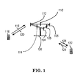
- FIG. 1 shows a multiple access wireless communication system according to one embodiment of the invention.
- An access network 100 includes multiple antenna groups, one including 104 and 106, another including 108 and 110, and an additional including 112 and 114. In FIG. 1 , only two antennas are shown for each antenna group, however, more or fewer antennas may be utilized for each antenna group.
- Access terminal 116 is in communication with antennas 112 and 114, where antennas 112 and 114 transmit information to access terminal 116 over forward link 120 and receive information from access terminal 116 over reverse link 118.
- Access terminal (AT) 122 is in communication with antennas 106 and 108, where antennas 106 and 108 transmit information to access terminal (AT) 122 over forward link 126 and receive information from access terminal (AT) 122 over reverse link 124.
- communication links 118, 120, 124 and 126 may use different frequency for communication.
- forward link 120 may use a different frequency then that used by reverse link 118.
- antenna groups each are designed to communicate to access terminals in a sector of the areas covered by access network 100.
- the transmitting antennas of access network 100 may utilize beamforming in order to improve the signal-to-noise ratio of forward links for the different access terminals 116 and 122. Also, an access network using beamforming to transmit to access terminals scattered randomly through its coverage causes less interference to access terminals in neighboring cells than an access network transmitting through a single antenna to all its access terminals.
- An access network may be a fixed station or base station used for communicating with the terminals and may also be referred to as an access point, a Node B, a base station, an enhanced base station, an eNB, or some other terminology.
- An access terminal may also be called user equipment (UE), a wireless communication device, terminal, access terminal or some other terminology.
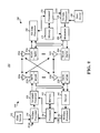
- FIG. 2 is a simplified block diagram of an embodiment of a transmitter system 210 (also known as the access network) and a receiver system 250 (also known as access terminal (AT) or user equipment (UE)) in a MIMO system 200.
- a transmitter system 210 also known as the access network
- a receiver system 250 also known as access terminal (AT) or user equipment (UE)
- traffic data for a number of data streams is provided from a data source 212 to a transmit (TX) data processor 214.
- TX transmit
- each data stream is transmitted over a respective transmit antenna.
- TX data processor 214 formats, codes, and interleaves the traffic data for each data stream based on a particular coding scheme selected for that data stream to provide coded data.
- the coded data for each data stream may be multiplexed with pilot data using OFDM techniques.
- the pilot data is typically a known data pattern that is processed in a known manner and may be used at the receiver system to estimate the channel response.
- the multiplexed pilot and coded data for each data stream is then modulated (i.e., symbol mapped) based on a particular modulation scheme (e.g., BPSK, QPSK, M-PSK, or M-QAM) selected for that data stream to provide modulation symbols.
- a particular modulation scheme e.g., BPSK, QPSK, M-PSK, or M-QAM
- the data rate, coding, and modulation for each data stream may be determined by instructions performed by processor 230.
- TX MIMO processor 220 may further process the modulation symbols (e.g., for OFDM).
- TX MIMO processor 220 then provides N T modulation symbol streams to N T transmitters (TMTR) 222a through 222t.
- TMTR TX MIMO processor 220 applies beamforming weights to the symbols of the data streams and to the antenna from which the symbol is being transmitted.
- Each transmitter 222 receives and processes a respective symbol stream to provide one or more analog signals, and further conditions (e.g., amplifies, filters, and upconverts) the analog signals to provide a modulated signal suitable for transmission over the MIMO channel.
- N T modulated signals from transmitters 222a through 222t are then transmitted from N T antennas 224a through 224t, respectively.
- the transmitted modulated signals are received by N R antennas 252a through 252r and the received signal from each antenna 252 is provided to a respective receiver (RCVR) 254a through 254r.
- Each receiver 254 conditions (e.g., filters, amplifies, and downconverts) a respective received signal, digitizes the conditioned signal to provide samples, and further processes the samples to provide a corresponding "received" symbol stream.
- An RX data processor 260 then receives and processes the N R received symbol streams from N R receivers 254 based on a particular receiver processing technique to provide N T "detected" symbol streams.
- the RX data processor 260 then demodulates, deinterleaves, and decodes each detected symbol stream to recover the traffic data for the data stream.
- the processing by RX data processor 260 is complementary to that performed by TX MIMO processor 220 and TX data processor 214 at transmitter system 210.
- a processor 270 periodically determines which pre-coding matrix to use (discussed below). Processor 270 formulates a reverse link message comprising a matrix index portion and a rank value portion.
- the reverse link message may comprise various types of information regarding the communication link and/or the received data stream.
- the reverse link message is then processed by a TX data processor 238, which also receives traffic data for a number of data streams from a data source 236, modulated by a modulator 280, conditioned by transmitters 254a through 254r, and transmitted back to transmitter system 210.
- the modulated signals from receiver system 250 are received by antennas 224, conditioned by receivers 222, demodulated by a demodulator 240, and processed by a RX data processor 242 to extract the reserve link message transmitted by the receiver system 250.
- Processor 230 determines which pre-coding matrix to use for determining the beamforming weights then processes the extracted message.
- FIG. 3 shows an alternative simplified functional block diagram of a communication device according to one embodiment of the invention.
- the communication device 300 in a wireless communication system can be utilized for realizing the UEs (or ATs) 116 and 122 in FIG. 1 , and the wireless communications system is preferably the LTE system.
- the communication device 300 may include an input device 302, an output device 304, a control circuit 306, a central processing unit (CPU) 308, a memory 310, a program code 312, and a transceiver 314.
- the control circuit 306 executes the program code 312 in the memory 310 through the CPU 308, thereby controlling an operation of the communications device 300.
- the communications device 300 can receive signals input by a user through the input device 302, such as a keyboard or keypad, and can output images and sounds through the output device 304, such as a monitor or speakers.
- the transceiver 314 is used to receive and transmit wireless signals, delivering received signals to the control circuit 306, and outputting signals generated by the control circuit 306 wirelessly.
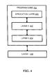
- FIG. 4 is a simplified block diagram of the program code 312 shown in FIG. 3 in accordance with one embodiment of the invention.
- the program code 312 includes an application layer 400, a Layer 3 portion 402, and a Layer 2 portion 404, and is coupled to a Layer 1 portion 406.
- the Layer 3 portion 402 generally performs radio resource control.
- the Layer 2 portion 404 generally performs link control.
- the Layer 1 portion 406 generally performs physical connections.
- the Layer 2 portion may include a Radio Link Control (RLC) layer and a Medium Access Control (MAC) layer.
- the Layer 3 portion may include a Radio Resource Control (RRC) layer.
- RLC Radio Link Control
- MAC Medium Access Control
- RRC Radio Resource Control
- 3GPP RP-122032 a new study item for small cell enhancements on physical layer aspects for release-12 was disclosed. The objective of this study item is described in 3GPP RP-122032 as follows:
- the objective of this study is to identify potential enhancements to improve the spectrum efficiency as well as efficient small cell deployment and operation in order to meet the requirements targeted for small cell enhancements in the identified scenarios in TR36.932, and evaluate the corresponding gain, standardization impact and complexity.
- the study should address small cell deployments on both a separate and the same frequency layer as the macro cells, taking into account existing mechanisms (e.g., CoMP, FeICIC) wherever applicable.
- existing mechanisms e.g., CoMP, FeICIC
- Backward compatibility i.e. the possibility for legacy (pre-R12) UEs to access a small-cell node/carrier, shall be guaranteed (except for features studied for small-cells using NCT) and the ability for legacy (pre-Rel-12) UEs to benefit from small-cell enhancements can be considered, which shall be taken into account in the evaluation of the different proposed enhancements.
- the introduction of non-backwards compatible features should be justified by sufficient gains.
- 3GPP TR36.872 contains the result of the study item "Small Cell Enhancements for E-UTRA and E-UTRAN - Physical-layer Aspects " and describes the mechanisms to reduce the time scales for small cell on/off transitions as quoted below:
- small cell on/off feasible time scales can be reduced to less than 100milliseconds.
- the time scale of small cell on/off transitions can be reduced by utilizing discovery signals and dual connectivity, which can eliminate the need of handover to and from a small cell.
- Secondary Cell (Scell) related procedures i.e., SCell addition/removal (as discussed in TS36.331 V11.4.0) and SCell activation/deactivation (as discussed in TS36.321 V11.3.0)
- SCell addition/removal as discussed in TS36.331 V11.4.0
- SCell activation/deactivation as discussed in TS36.321 V11.3.0
- further enhancement to support small cell on/off transitions should be considered.
- an SCell may be deactivated because of poor reception quality.
- the UE needs to perform measurements on the cell-specific reference signal (CRS) of a SCell after this SCell has been deactivated so that it could be activated again later if the reception quality becomes better again.
- CRS cell-specific reference signal
- the UE should measure the discovery signal of the small cell instead. Therefore, the UE should be aware of which signal to measure after the SCell is deactivated.
- a straightforward way is to apply the legacy measurement reconfiguration procedure to indicate the measured signal.
- the macro eNB sends a Radio Resource Control (RRC) Connection Reconfiguration message to modify the measurement configuration every time when the SCell is deactivated.
- RRC Radio Resource Control
- the macro eNB it would be more efficient in terms of signaling resource usage for the macro eNB to include a field in the Activation/Deactivation MAC control element to indicate which signal (namely the discovery signal or the CRS) of the small cell should be measured assuming that the UE had already received the configuration of the discovery signal before (e.g., when the small cell is configured to the UE or when measurement on the small cell is firstly configured to the UE).
- a new MAC control element or PDCCH (Physical Downlink Control Channel) signaling can be defined for the macro eNB to indicate to the UE which signal of the small cell should be measured.
- the macro eNB sends a signaling to the UE to indicate whether the small cell is on or off. Based on this indicator, the UE can determine which signal of the small cell should be measured.
- the discovery signal can be newly designed.
- the discovery signal can be formed from a legacy signal with reduced periodicity. Examples of such legacy signal include PSS (Primary Synchronization Signal), SSS (Secondary Synchronization Signal, and CRS. All of the embodiments indicated in paragraphs [0036] to [0039] can be combined in any combination of two or more of the embodiments. Also, alternatives or embodiments that are described as alternatives might be combined with any other of the embodiments, e.g. for a method or device that performs both or more of the embodiments in combination or alternatively.
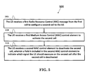
- FIG. 5 illustrates one exemplary method 500 for changing a measured signal on a cell, wherein a user equipment (UE) is served by a first cell, according to the invention.
- the UE receives a first Radio Resource Control (RRC) message from the first cell to configure a second cell to the UE.
- RRC Radio Resource Control
- the UE receives a first Medium Access Control (MAC) control element to activate the second cell.
- the UE receives a second MAC control element to deactivate the second cell, wherein a field is included in the second MAC control element to indicate which signal the UE should measure on the second cell after the second cell is deactivated.
- RRC Radio Resource Control
- MAC Medium Access Control
- the device 300 includes a program code 312 stored in memory 310 for changing measured signal on a cell, wherein a UE is served by a first cell.
- the CPU 308 could execute program code 312 to enable the UE (i) to receive a first RRC message from the first cell to configure a second cell to the UE, (ii) to receive a first MAC control element to activate the second cell, and (iii) to receive a second MAC control element to deactivate the second cell, wherein a field is included in the second MAC control element to indicate which signal the UE should measure on the second cell after the second cell is deactivated.
- the CPU 308 can execute the program code 312 to perform all of the above-described actions and steps or others described herein, in particular those as described in paragraph [0040] above.
- the first RRC message includes a configuration of a discovery signal on the second cell.
- the first RRC message is a RRC Connection Reconfiguration message.
- the first MAC control element is an Activation/Deactivation MAC control element.
- the second MAC control element is an Activation/Deactivation MAC control element.
- those signals for the UE to measure contain at least a discovery signal and a cell-specific reference signal (CRS).
- the discovery signal is formed from a legacy signal having a reduced periodicity, wherein the legacy signal is a Primary Synchronization Signal (PSS)/Secondary Synchronization Signal (SSS) or CRS.
- PSS Primary Synchronization Signal
- SSS Secondary Synchronization Signal
- CRS CRS
- FIG. 6 illustrates another exemplary method 600 changing a measured signal on a cell, wherein a first cell serves a UE, according to the invention.
- the first cell sends a first Radio Resource Control (RRC) message to the UE to configure a second cell to the UE.
- RRC Radio Resource Control
- the first cell sends a first Medium Access Control (MAC) control element to the UE to activate the second cell.
- MAC Medium Access Control
- the first cell sends a second MAC control element to deactivate the second cell, wherein a field is included in the second MAC control element to indicate which signal on the second cell for the UE to measure after the second cell is deactivated.
- the device 300 includes a program code 312 stored in memory 310 for changing measured signal on a cell, wherein a first cell serves a UE.
- the CPU 308 could execute program code 312 to enable the first cell to (i) to send a first RRC message to the UE to configure a second cell to the UE, (ii) to send a first MAC control element to the UE to activate the second cell, and (iii) to send a second MAC control element to deactivate the second cell, wherein a field is included in the second MAC control element to indicate which signal on the second cell for the UE to measure after the second cell is deactivated.
- the CPU 308 can execute the program code 312 to perform all of the above-described actions and steps or others described herein, in particular those described in paragraph [0043] above.
- the first RRC message includes a configuration of a discovery signal on the second cell.
- the first RRC message is a RRC Connection Reconfiguration message.
- the first MAC control element is an Activation/Deactivation MAC control element.
- the second MAC control element is an Activation/Deactivation MAC control element.
- those signals for the UE to measure contain at least a discovery signal and a cell-specific reference signal (CRS).
- the discovery signal is formed from a legacy signal having a reduced periodicity, in which the legacy signal could be a Primary Synchronization Signal (PSS)/Secondary Synchronization Signal (SSS) or CRS.
- the discovery signal on the second cell is transmitted by the second cell for the UE to discover the second cell.
- concurrent channels may be established based on pulse repetition frequencies.
- concurrent channels may be established based on pulse position or offsets.
- concurrent channels may be established based on time hopping sequences.
- concurrent channels may be established based on pulse repetition frequencies, pulse positions or offsets, and time hopping sequences.
- the various illustrative logical blocks, modules, and circuits described in connection with the aspects disclosed herein may be implemented within or performed by an integrated circuit ("IC"), an access terminal, or an access point.
- the IC may comprise a general purpose processor, a digital signal processor (DSP), an application specific integrated circuit (ASIC), a field programmable gate array (FPGA) or other programmable logic device, discrete gate or transistor logic, discrete hardware components, electrical components, optical components, mechanical components, or any combination thereof designed to perform the functions described herein, and may execute codes or instructions that reside within the IC, outside of the IC, or both.
- a general purpose processor may be a microprocessor, but in the alternative, the processor may be any conventional processor, controller, microcontroller, or state machine.
- a processor may also be implemented as a combination of computing devices, e.g., a combination of a DSP and a microprocessor, a plurality of microprocessors, one or more microprocessors in conjunction with a DSP core, or any other such configuration.
- a software module e.g., including executable instructions and related data
- other data may reside in a data memory such as RAM memory, flash memory, ROM memory, EPROM memory, EEPROM memory, registers, a hard disk, a removable disk, a CD-ROM, or any other form of computer-readable storage medium known in the art.
- a sample storage medium may be coupled to a machine such as, for example, a computer/processor (which may be referred to herein, for convenience, as a "processor") such the processor can read information (e.g., code) from and write information to the storage medium.
- a sample storage medium may be integral to the processor.
- the processor and the storage medium may reside in an ASIC.
- the ASIC may reside in user equipment.
- the processor and the storage medium may reside as discrete components in user equipment.
- any suitable computer-program product may comprise a computer-readable medium comprising codes relating to one or more of the aspects of the disclosure.
- a computer program product may comprise packaging materials.
Landscapes
- Engineering & Computer Science (AREA)
- Computer Networks & Wireless Communication (AREA)
- Signal Processing (AREA)
- Databases & Information Systems (AREA)
- Computer Security & Cryptography (AREA)
- Mobile Radio Communication Systems (AREA)
Applications Claiming Priority (1)
| Application Number | Priority Date | Filing Date | Title |
|---|---|---|---|
| US201361886850P | 2013-10-04 | 2013-10-04 |
Publications (1)
| Publication Number | Publication Date |
|---|---|
| EP2879433A1 true EP2879433A1 (de) | 2015-06-03 |
Family
ID=51661919
Family Applications (3)
| Application Number | Title | Priority Date | Filing Date |
|---|---|---|---|
| EP14187441.2A Withdrawn EP2879458A1 (de) | 2013-10-04 | 2014-10-02 | Verfahren und Vorrichtung zur Unterstützung von Vorrichtung-zu-Vorrichtung (D2D)-Erfassung in einem drahtlosen Kommunikationssystem |
| EP14187456.0A Withdrawn EP2879433A1 (de) | 2013-10-04 | 2014-10-02 | Verfahren und Vorrichtung für Kleinzellenverbesserungen in einem drahtlosen Kommunikationssystem |
| EP14187448.7A Active EP2887711B1 (de) | 2013-10-04 | 2014-10-02 | Verfahren und vorrichtung zur unterstützung von vorrichtung-zu-vorrichtung (d2d)-erfassung in einem drahtlosen kommunikationssystem |
Family Applications Before (1)
| Application Number | Title | Priority Date | Filing Date |
|---|---|---|---|
| EP14187441.2A Withdrawn EP2879458A1 (de) | 2013-10-04 | 2014-10-02 | Verfahren und Vorrichtung zur Unterstützung von Vorrichtung-zu-Vorrichtung (D2D)-Erfassung in einem drahtlosen Kommunikationssystem |
Family Applications After (1)
| Application Number | Title | Priority Date | Filing Date |
|---|---|---|---|
| EP14187448.7A Active EP2887711B1 (de) | 2013-10-04 | 2014-10-02 | Verfahren und vorrichtung zur unterstützung von vorrichtung-zu-vorrichtung (d2d)-erfassung in einem drahtlosen kommunikationssystem |
Country Status (7)
| Country | Link |
|---|---|
| US (3) | US20150098414A1 (de) |
| EP (3) | EP2879458A1 (de) |
| JP (2) | JP2015076886A (de) |
| KR (1) | KR101719121B1 (de) |
| CN (2) | CN107734490B (de) |
| ES (1) | ES2929142T3 (de) |
| TW (1) | TWI566636B (de) |
Families Citing this family (34)
| Publication number | Priority date | Publication date | Assignee | Title |
|---|---|---|---|---|
| AU2014305302B2 (en) * | 2013-08-07 | 2018-05-17 | Samsung Electronics Co., Ltd. | Method and apparatus for transmitting and receiving resource allocation information in a wireless communication system |
| US20150089382A1 (en) * | 2013-09-26 | 2015-03-26 | Wu-chi Feng | Application context migration framework and protocol |
| CN110536485B (zh) * | 2013-09-27 | 2022-12-23 | Sk电信有限公司 | 支持双连接的用户设备 |
| JP6183148B2 (ja) * | 2013-10-24 | 2017-08-23 | 富士通株式会社 | 通信端末装置、通信制御システムおよび通信制御方法 |
| KR102163480B1 (ko) * | 2013-12-12 | 2020-10-07 | 후아웨이 테크놀러지 컴퍼니 리미티드 | 단말 간 직접 통신에서 탐색 자원 할당을 위한 단말 간 스케줄링 방법 및 그 장치 |
| US10791476B2 (en) | 2013-12-12 | 2020-09-29 | Lg Electronics Inc. | Method and device for performing measurement in wireless communication system |
| CN110933658B (zh) * | 2014-01-29 | 2022-11-15 | 交互数字专利控股公司 | 用于设备到设备发现或通信的资源选择 |
| US10721720B2 (en) * | 2014-01-30 | 2020-07-21 | Qualcomm Incorporated | Cell On-Off procedure for dual connectivity |
| US9867073B2 (en) * | 2014-01-30 | 2018-01-09 | Intel IP Corporation | Measurement gap repetition patterns for inter-frequency offloading in heterogeneous wireless networks |
| US10219217B2 (en) * | 2014-01-31 | 2019-02-26 | Telefonaktiebolaget Lm Ericsson (Publ) | Assisting measurements in small cells with an on/off scheme |
| CN106031271A (zh) * | 2014-02-20 | 2016-10-12 | 诺基亚通信公司 | 配置物理信道资源用于半双工通信环境中的探测或发现 |
| US9992744B2 (en) * | 2014-02-24 | 2018-06-05 | Intel Corporation | Mechanisms to optimize and align discontinuous reception configuration of device to-device capable user equipment |
| US10200185B2 (en) * | 2014-02-26 | 2019-02-05 | Lg Electronics Inc. | Method for monitoring PDCCH in FDD half-duplex communication and terminal thereof |
| US9888519B2 (en) | 2014-03-24 | 2018-02-06 | Samsung Electronics Co., Ltd. | Apparatus and method for monitoring D2D transmission in connected state |
| US20160014794A1 (en) * | 2014-07-08 | 2016-01-14 | Htc Corporation | Device and Method of Handling Device-to-Device communication |
| EP3179805A4 (de) * | 2014-08-08 | 2018-06-13 | Kyocera Corporation | Benutzerendgerät |
| KR101893313B1 (ko) * | 2014-08-11 | 2018-08-29 | 텔레폰악티에볼라겟엘엠에릭슨(펍) | D2d 및 셀룰러 동작 |
| CN107079395A (zh) * | 2014-10-17 | 2017-08-18 | 株式会社Ntt都科摩 | 用户装置、基站以及间歇接收方法 |
| CN107079276B (zh) * | 2014-10-21 | 2021-06-22 | Lg电子株式会社 | 在无线通信系统中发送/接收d2d信号的方法及其设备 |
| US9706591B2 (en) * | 2014-11-05 | 2017-07-11 | Intel Corporation | Device to-device (D2D) transmit behavior |
| JP6276415B2 (ja) * | 2014-11-07 | 2018-02-07 | 京セラ株式会社 | 基地局、ユーザ端末及びプロセッサ |
| US9807713B2 (en) * | 2014-11-14 | 2017-10-31 | Telefonaktiebolaget Lm Ericsson (Publ) | Synchronization in communications networks |
| KR102482789B1 (ko) * | 2015-08-07 | 2022-12-29 | 샤프 가부시키가이샤 | 단말 장치, 기지국 장치, 통신 시스템, 측정 방법 및 집적 회로 |
| WO2017062278A1 (en) * | 2015-10-05 | 2017-04-13 | Intel IP Corporation | Rrm requirement for d2d inter-carrier discovery gap |
| EP3360351B1 (de) * | 2015-11-12 | 2019-11-13 | Sony Corporation | Telekommunikationsvorrichtungen und -verfahren |
| CN106817745B (zh) * | 2015-12-01 | 2019-12-20 | 普天信息技术有限公司 | 一种集群dmo用户设备寻呼与反馈方法 |
| US11172389B2 (en) * | 2016-03-31 | 2021-11-09 | Intel Corporation | Measurement gap configuration |
| CN109792679B (zh) * | 2016-08-11 | 2020-12-04 | 华为技术有限公司 | 通信方法、装置及设备 |
| MX2019007899A (es) * | 2016-12-30 | 2020-01-27 | Guangdong Oppo Mobile Telecommunications Corp Ltd | Metodo de transmision de informacion, dispositivo de red y dispositivo terminal. |
| KR101943328B1 (ko) * | 2017-03-23 | 2019-01-29 | 엘지전자 주식회사 | 하향링크 신호를 수신하는 방법 및 사용자기기 |
| US20180332537A1 (en) * | 2017-05-10 | 2018-11-15 | Qualcomm Incorporated | Methods and apparatus for intelligent monitoring in discovery periods |
| US10764776B2 (en) * | 2017-11-10 | 2020-09-01 | Qualcomm Incorporated | Measurement gap enhancements for BL/CE UEs |
| CN111096009B (zh) * | 2018-02-14 | 2022-09-16 | Lg 电子株式会社 | 无线通信系统中发送和接收用于寻呼的控制信息的方法及其装置 |
| CN113260024B (zh) * | 2020-02-10 | 2022-08-26 | 大唐移动通信设备有限公司 | 一种非连续接收定时器管理方法及终端 |
Family Cites Families (39)
| Publication number | Priority date | Publication date | Assignee | Title |
|---|---|---|---|---|
| CN101247642B (zh) * | 2007-02-14 | 2012-12-19 | 华为技术有限公司 | 安全邻居发现方法、网络设备和移动台 |
| US8320398B2 (en) | 2007-07-10 | 2012-11-27 | Qualcomm Incorporated | Paging a peer in a peer-to-peer communication network |
| JP2009111630A (ja) * | 2007-10-29 | 2009-05-21 | Toshiba Corp | 移動無線端末装置 |
| JP2011525095A (ja) * | 2008-06-20 | 2011-09-08 | インターデイジタル パテント ホールディングス インコーポレイテッド | システム情報ブロードキャストにおける緊急情報 |
| CN107181582B (zh) * | 2009-04-28 | 2020-07-31 | 三菱电机株式会社 | 移动通信系统 |
| DK2554013T3 (da) * | 2010-03-30 | 2019-10-21 | Nokia Technologies Oy | Fremgangsmåde og apparat til opdagelse af anordninger ved beaconing |
| US8868743B2 (en) * | 2010-04-30 | 2014-10-21 | Sharp Kabushiki Kaisha | Modified access classes for machine type communication (MTC) devices during emergencies |
| US8744458B2 (en) * | 2010-11-19 | 2014-06-03 | Nokia Corporation | Signaling mixed resource allocations for D2D communications |
| EP3522579B1 (de) * | 2011-02-14 | 2021-02-03 | Huawei Technologies Co., Ltd. | Steuerkanalübertragungs- und empfangsverfahren und system dafür |
| EP2715981B1 (de) * | 2011-06-01 | 2018-11-28 | NTT DoCoMo, Inc. | Erweiterter lokaler zugriff in mobilkommunikationen |
| WO2013012222A2 (ko) * | 2011-07-21 | 2013-01-24 | 엘지전자 주식회사 | 무선 기기들 사이의 통신 방법 및 이를 이용하는 무선 기기 |
| US20130029712A1 (en) * | 2011-07-26 | 2013-01-31 | Samsung Electronics Co., Ltd. | Device/service discovery and channel access control for proximity device-to-device wireless communication |
| WO2013025057A2 (ko) * | 2011-08-16 | 2013-02-21 | 엘지전자 주식회사 | 무선 접속 시스템에서 단말 간 통신 수행 방법 및 이를 위한 장치 |
| US9253713B2 (en) * | 2011-09-26 | 2016-02-02 | Blackberry Limited | Method and system for small cell discovery in heterogeneous cellular networks |
| US8848700B2 (en) * | 2011-09-30 | 2014-09-30 | Electronics And Telecommunications Research Institute | Method for device-to-device communication based on cellular telecommunication system |
| GB2496153B (en) * | 2011-11-02 | 2014-07-02 | Broadcom Corp | Device-to-device communications |
| WO2013074462A1 (en) * | 2011-11-14 | 2013-05-23 | Kyocera Corporation | Device-to-device communication management using macrocell communication resources |
| US9084180B2 (en) * | 2011-12-14 | 2015-07-14 | Qualcomm Incorporated | Systems and methods for transmitting and receiving discovery and paging messages |
| GB2497740B (en) * | 2011-12-19 | 2013-12-11 | Renesas Mobile Corp | Method,apparatus and computer program for device-to-device discovery |
| WO2013095000A1 (ko) * | 2011-12-20 | 2013-06-27 | 엘지전자 주식회사 | 근접 서비스 제공을 위한 네트워크-개시 제어 방법 및 장치 |
| US9036546B2 (en) * | 2012-01-04 | 2015-05-19 | Futurewei Technologies, Inc. | System and method for device discovery for device-to-device communication in a cellular network |
| US9214988B2 (en) * | 2012-02-06 | 2015-12-15 | Qualcomm Incorporated | Methods and apparatus for improving peer communications using an active communication mode |
| CN102547984B (zh) * | 2012-02-23 | 2015-03-11 | 华为技术有限公司 | 一种设备到设备通信中寻呼的方法及装置 |
| US20130229931A1 (en) * | 2012-03-02 | 2013-09-05 | Electronics And Telecommunications Research Institute | Methods of managing terminal performed in base station and terminal |
| KR101932984B1 (ko) * | 2012-03-02 | 2018-12-27 | 한국전자통신연구원 | 헤테로지니어스 네트워크 환경에서 단말기 관리 방법 |
| JPWO2013137424A1 (ja) * | 2012-03-16 | 2015-08-03 | 株式会社Nttドコモ | 移動局及び無線基地局 |
| CN103327568B (zh) * | 2012-03-21 | 2016-12-14 | 中国移动通信集团公司 | 资源分配消息发送方法、设备发现方法及相关设备 |
| WO2013176822A2 (en) * | 2012-05-25 | 2013-11-28 | Motorola Mobility Llc | Reducing the effects of interference experienced by a communication device |
| TWI620459B (zh) * | 2012-05-31 | 2018-04-01 | 內數位專利控股公司 | 在蜂巢式通訊系統中賦能直鏈通訊排程及控制方法 |
| WO2013187605A1 (ko) * | 2012-06-15 | 2013-12-19 | 엘지전자 주식회사 | 무선 통신 시스템에서 단말 간 직접 통신을 위한 단말 검출 방법 및 이를 위한 장치 |
| US10028204B2 (en) * | 2012-08-24 | 2018-07-17 | Blackberry Limited | Supporting device-to-device communication in a rich communication service context |
| CN102857901A (zh) * | 2012-09-12 | 2013-01-02 | 中兴通讯股份有限公司 | 终端的发现、发现处理方法及装置 |
| US20140094212A1 (en) * | 2012-09-28 | 2014-04-03 | Electronics And Telecommunications Research Institute | Method of device to device discovery and apparatus thereof |
| CN103024911A (zh) * | 2012-11-30 | 2013-04-03 | 北京邮电大学 | 蜂窝与d2d混合网络中终端直通通信的数据传输方法 |
| CN103229582B (zh) * | 2012-12-24 | 2017-05-24 | 华为技术有限公司 | 资源竞争的方法、利用资源竞争的方法及其装置 |
| EP2925067B1 (de) * | 2012-12-31 | 2018-02-28 | Huawei Technologies Co., Ltd. | Vorrichtung-zu-vorrichtung-kommunikationsverfahren und -system |
| US9398438B2 (en) * | 2013-05-10 | 2016-07-19 | Futurewei Technologies, Inc. | System and method for TDD configuration for D2D open discovery |
| US20150043446A1 (en) * | 2013-08-12 | 2015-02-12 | Qualcomm Incorporated | Method and apparatus for coexistence of device to device and lte wan communication using single communication chain |
| US9369961B2 (en) * | 2014-06-05 | 2016-06-14 | Sony Corporation | User equipment, cellular communication network node and method of controlling operation of a user equipment |
-
2014
- 2014-09-29 US US14/499,974 patent/US20150098414A1/en not_active Abandoned
- 2014-09-29 US US14/500,075 patent/US20150098416A1/en not_active Abandoned
- 2014-09-30 KR KR1020140131336A patent/KR101719121B1/ko active Active
- 2014-09-30 US US14/502,070 patent/US20150099503A1/en not_active Abandoned
- 2014-10-02 EP EP14187441.2A patent/EP2879458A1/de not_active Withdrawn
- 2014-10-02 EP EP14187456.0A patent/EP2879433A1/de not_active Withdrawn
- 2014-10-02 EP EP14187448.7A patent/EP2887711B1/de active Active
- 2014-10-02 ES ES14187448T patent/ES2929142T3/es active Active
- 2014-10-02 TW TW103134346A patent/TWI566636B/zh active
- 2014-10-03 JP JP2014205103A patent/JP2015076886A/ja active Pending
- 2014-10-08 CN CN201711096613.XA patent/CN107734490B/zh active Active
- 2014-10-08 CN CN201410526644.4A patent/CN104519474A/zh active Pending
-
2016
- 2016-02-15 JP JP2016026315A patent/JP6161746B2/ja active Active
Non-Patent Citations (7)
| Title |
|---|
| "E-UTRA MAC protocol specification", TS36.321 VI 1.3.0 |
| "E-UTRA RRC protocol specification", TS36.331 VI 1.4.0 |
| "Small Cell Enhancements for E-UTRA and E-UTRAN - Physical layer Aspects (Release 12", TR36.872-101 |
| "Study on Small Cell enhancements for E-UTRA and E-UTRAN - Physical-layer aspects", RP-122032 |
| INTEL CORPORATION: "Discussion on the maximum size of CoMP measurement set", 3GPP DRAFT; R1-121521 DISCUSSION ON THE MAXIMUM SIZE OF COMP MEASURMENT SET, 3RD GENERATION PARTNERSHIP PROJECT (3GPP), MOBILE COMPETENCE CENTRE ; 650, ROUTE DES LUCIOLES ; F-06921 SOPHIA-ANTIPOLIS CEDEX ; FRANCE, vol. RAN WG1, no. Jeju, Korea; 20120326 - 20120330, 20 March 2012 (2012-03-20), XP050599794 * |
| SAMSUNG: "Cell discovery for efficient small cell operation", vol. RAN WG1, no. Fukuoka, Japan; 20130520 - 20130524, 11 May 2013 (2013-05-11), XP050697764, Retrieved from the Internet <URL:http://www.3gpp.org/ftp/tsg_ran/WG1_RL1/TSGR1_73/Docs/> [retrieved on 20130511] * |
| SHARP: "PCell vs. SCell with PUCCH for inter-eNB CA", vol. RAN WG2, no. Fukuoka, Japan; 20130520 - 20130524, 11 May 2013 (2013-05-11), XP050700141, Retrieved from the Internet <URL:http://www.3gpp.org/ftp/tsg_ran/WG2_RL2/TSGR2_82/Docs/> [retrieved on 20130511] * |
Also Published As
| Publication number | Publication date |
|---|---|
| US20150098414A1 (en) | 2015-04-09 |
| CN104519474A (zh) | 2015-04-15 |
| TW201515504A (zh) | 2015-04-16 |
| EP2887711B1 (de) | 2022-07-27 |
| KR101719121B1 (ko) | 2017-03-23 |
| EP2879458A1 (de) | 2015-06-03 |
| JP2016116241A (ja) | 2016-06-23 |
| EP2887711A2 (de) | 2015-06-24 |
| US20150098416A1 (en) | 2015-04-09 |
| CN107734490B (zh) | 2020-12-01 |
| KR20150040221A (ko) | 2015-04-14 |
| JP6161746B2 (ja) | 2017-07-12 |
| ES2929142T3 (es) | 2022-11-25 |
| TWI566636B (zh) | 2017-01-11 |
| CN107734490A (zh) | 2018-02-23 |
| US20150099503A1 (en) | 2015-04-09 |
| EP2887711A3 (de) | 2015-11-18 |
| JP2015076886A (ja) | 2015-04-20 |
Similar Documents
| Publication | Publication Date | Title |
|---|---|---|
| EP2879433A1 (de) | Verfahren und Vorrichtung für Kleinzellenverbesserungen in einem drahtlosen Kommunikationssystem | |
| JP7675126B2 (ja) | 超高信頼低遅延通信表示チャネル化設計 | |
| KR102137311B1 (ko) | 무선 통신 시스템에서 랜덤 액세스 구성을 위한 방법 및 장치 | |
| US11129036B2 (en) | Method and apparatus for estimating pathloss of PUSCH in a wireless communication system | |
| JP6625170B2 (ja) | 無線通信システムにおけるsfi(スロットフォーマット情報)衝突を処理するための方法及び装置 | |
| EP2822351B1 (de) | Verfahren und Vorrichtung zur Überwachung einer Funkverbindung auf einer kleinen Zelle in einem drahtlosen Kommunikationssystem | |
| EP3547782A1 (de) | Verfahren und vorrichtung zur strahlanzeige unter berücksichtigung von trägerübergreifender zeitplanung in einem drahtloskommunikationssystem | |
| JP2020028131A (ja) | 無線通信システムにおける複数のデバイス・ツー・デバイス・リソースプールに対するリソースを割り当てる方法および装置 | |
| WO2021155586A1 (en) | Sounding reference signal (srs) enhancements | |
| EP3010301B1 (de) | Verfahren und vorrichtung zur verbesserung der ressourcensteuerung in einem drahtloskommunikationssystem | |
| US20130272234A1 (en) | Method and apparatus for interpreting content of a downlink resource allocation field in a user equipment (ue) in a wireless communication network | |
| US20110159867A1 (en) | Method and apparatus to allocate random access channel (rach) resources for carrier aggregation in a wireless communication network | |
| CN112313899A (zh) | 针对传输模式切换的信道状态信息测量与反馈 | |
| EP2688357B1 (de) | Verfahren und Vorrichtung zur Verringerung des Signalisierungsaufwands in einem drahtlosen Kommunikationsnetzwerk | |
| US20150245334A1 (en) | Method and apparatus for device to device service in a wireless communication system | |
| EP2757733B1 (de) | Verfahren und Vorrichtung zur Messung von Kanalstatusinformationen in einem drahtlosen Kommunikationssystem | |
| EP2592873A1 (de) | Verfahren und Vorrichtung zur Verbesserung von Niedrigkosten-MTC (Maschinentypkommunikations-) Vorrichtungen in einem drahtlosen Kommunikationssystem | |
| EP2765798B1 (de) | Verfahren und Vorrichtung zur Durchführung von kleinzelligen Verbesserungen in einem drahtlosen Kommunikationssystem | |
| JP2020014209A (ja) | 無線通信システムにおいてスロットフォーマットを決定するのための方法および装置 | |
| US20110103331A1 (en) | Method and apparatus to activate component carriers in a wireless communication network | |
| EP2770661A1 (de) | Verfahren und Vorrichtung zur Konnektivität zwischen Knoten in einem drahtlosen Kommunikationssystem | |
| JP7739422B2 (ja) | 異なる優先度をもつスケジュールドアップリンク反復送信のためのキャンセル順序 | |
| CN114223149A (zh) | 多波束nr-u中的波束故障检测和候选波束检测的评估时段 | |
| US20140078989A1 (en) | METHOD AND APPARATUS FOR IMPROVING INTER-eNB CARRIER AGGREGATION IN A WIRELESS COMMUNICATION SYSTEM | |
| EP2809017A1 (de) | Verfahren und Vorrichtung zur Bündelung von TTI (Übertragungszeitintervall) für Kleinzellenverbesserungen in einem drahtlosen Kommunikationssystem |
Legal Events
| Date | Code | Title | Description |
|---|---|---|---|
| PUAI | Public reference made under article 153(3) epc to a published international application that has entered the european phase |
Free format text: ORIGINAL CODE: 0009012 |
|
| 17P | Request for examination filed |
Effective date: 20141002 |
|
| AK | Designated contracting states |
Kind code of ref document: A1 Designated state(s): AL AT BE BG CH CY CZ DE DK EE ES FI FR GB GR HR HU IE IS IT LI LT LU LV MC MK MT NL NO PL PT RO RS SE SI SK SM TR |
|
| AX | Request for extension of the european patent |
Extension state: BA ME |
|
| STAA | Information on the status of an ep patent application or granted ep patent |
Free format text: STATUS: THE APPLICATION IS DEEMED TO BE WITHDRAWN |
|
| 18D | Application deemed to be withdrawn |
Effective date: 20151204 |