EP2879932B1 - Hilfsaggregategerüst für eine elektrolokomotive - Google Patents
Hilfsaggregategerüst für eine elektrolokomotive Download PDFInfo
- Publication number
- EP2879932B1 EP2879932B1 EP13753839.3A EP13753839A EP2879932B1 EP 2879932 B1 EP2879932 B1 EP 2879932B1 EP 13753839 A EP13753839 A EP 13753839A EP 2879932 B1 EP2879932 B1 EP 2879932B1
- Authority
- EP
- European Patent Office
- Prior art keywords
- frame
- electric locomotive
- cooling air
- generator unit
- engine
- Prior art date
- Legal status (The legal status is an assumption and is not a legal conclusion. Google has not performed a legal analysis and makes no representation as to the accuracy of the status listed.)
- Active
Links
Images


Classifications
-
- B—PERFORMING OPERATIONS; TRANSPORTING
- B61—RAILWAYS
- B61C—LOCOMOTIVES; MOTOR RAILCARS
- B61C17/00—Arrangement or disposition of parts; Details or accessories not otherwise provided for; Use of control gear and control systems
- B61C17/04—Arrangement or disposition of driving cabins, footplates or engine rooms; Ventilation thereof
Definitions
- the invention relates to a scaffold for installation in an electrically driven locomotive in a predetermined installation position, which comprises at least one internal combustion engine and a generator connected thereto, which together form a motor / generator unit, and which scaffold at least one interface for a fuel supply and at least one Having an interface for a power output.
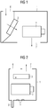
- Such scaffolding as in Fig. 1 illustrated longitudinally, are known in the art, for example by the TRAXX F140 AC with Last Mile engine, which comprises a cooling system for a motor / generator unit 2, which has at least one heat exchanger 3, which in the predetermined installation position of the frame 1 in the axial direction of the Electric locomotive is arranged in alignment with the motor / generator unit 2, whereby the framework 1 occupies a lot of space in the axial direction of the electric locomotive, which in addition leads to a high weight.
- a cooling air inlet 6 is arranged at the top in the framework 1, while a cooling air outlet 7 points downward from the framework 1 and at the same time also serves as residual water outlet. The cooling air is therefore guided longitudinally through the framework 1.
- the scaffolding is designed for a given electric locomotive and does not appear to be suitable for use at different locations or multiple times in the electric locomotive.
- the invention is based, to increase the flexibility to install a scaffold significantly the task.
- a rail vehicle according to the invention in particular an electric locomotive of rail transport, comprises a framework for installation in an electrically driven rail vehicle, in particular in an electric locomotive, which frame comprises at least one internal combustion engine, for example a diesel engine, and at least one generator connected to this internal combustion engine for generating electricity. Together they form a motor / generator unit.
- the framework additionally comprises a plurality of interfaces, including at least one interface for a fuel supply and at least one interface for a power output, for example an electrical plug connection for connecting a power cable to the generator.
- at least one interface for controlling at least one motor / generator unit may be provided, a so-called control connection.
- the scaffold is now constructed according to the invention so that the at least one interface for the fuel supply and the at least one interface for the power output in the predetermined installation position of the scaffold below the motor / generator unit are arranged, wherein the framework in the predetermined installation position has a side maintenance access , by which at least the motor / generator unit is freely accessible.
- the control connection or other interfaces are arranged below the engine. If the interfaces are arranged on the side and in the area of the maintenance access of the framework, they too are freely accessible through the maintenance access.
- the framework is arranged in the rail vehicle, that the maintenance access of the scaffolding is accessible from a corridor of the rail vehicle.
- the maintenance access therefore points to the corridor. More specifically, the service access is accessible only from the aisle.
- all maintenance components of the scaffolding are interchangeable with the at least one maintenance access.
- the at least one maintenance access for example exclusively by at least one, on one single side of the scaffold arranged maintenance access, which is accessible in particular from the corridor.
- a variant of the invention provides a maintenance access, which is accessible from outside, in particular through a side wall of the rail vehicle from the outside.
- a development of the invention is to be seen in that the at least one interface for the fuel supply and / or the at least one interface for the power output in the predetermined installation position of the scaffold point down from the framework. If an interface is designed, for example, as a plug connection, cables or hoses are led out of the framework downwards. According to one embodiment example is exactly one interface for the fuel supply and / or exactly one interface for the power delivery provided. Further developed, the interfaces only point down from the framework.
- the framework comprises a cooling system for the motor / generator unit, which has at least one heat exchanger which is arranged in the predetermined installation position of the framework above the motor / generator unit.
- the motor / generator unit is free from the heat exchanger, at least on the side of the maintenance access.
- the heat exchanger is freely accessible by the maintenance access according to an embodiment.
- Developed further comprises the framework at least one cooling air inlet and at least one cooling air outlet, which at least one cooling air outlet in the predetermined installation position of the scaffold upwards out of the frame, in order to air from above into the scaffold in or up from the Lead out scaffolding.
- the at least one cooling air inlet and / or which at least one cooling air outlet are correspondingly provided above the motor / generator unit in the framework.
- the cooling air inlet and / or the cooling air outlet are arranged above the heat exchanger.
- An alternative solution provides that cooling air is sucked from the engine room, for example, laterally to the motor / generator unit, ie by a laterally arranged cooling air inlet.
- the exhaust air can then also be blown upwards, that is to say through a cooling air outlet arranged above the motor / generator unit.
- a drainage system is provided in the framework, which is a collection trough for collecting water comprises which collecting trough is arranged in the predetermined installation position of the framework below the motor / generator unit.
- the sump has an outflow and an adjoining drainage pipe, which is led out down from the framework.
- the drain serves as the first access to the drainage pipe.
- Another access can be connected to an overflow pipe with an overflow opening, which overflow opening is arranged in the installation position of the scaffold above the outflow of the sump. The overflow is used for the discharge of collected water even with a clogged drain.
- the framework has a cooling system with a heat exchanger arranged above the motor / generator unit.
- the rail vehicle hereinafter only explained in detail the embodiment of an electric locomotive, comprise a cooling system for the motor / generator unit having at least one heat exchanger, which is arranged on a roof of the rail vehicle or underfloor. This makes possible an even more compact construction of the scaffolding, so that it can be used in many different constructed locomotives.
- the electric locomotive has a receiving unit for receiving in each case a scaffold.
- an adapter frame is provided.
- the electric locomotive comprises at least two ventilation openings in its outer skin, in particular in the roof.
- the adapter frame is then arranged to adapt the cooling air inlet and the cooling air outlet of the scaffold to the ventilation openings between the framework and the ventilation openings to guide air between at least one first ventilation opening and the cooling air inlet and between at least one further, second ventilation opening the cooling air outlet of the scaffold.
- the adapter frame comprises, for example, at least one ventilation duct between the at least one cooling air inlet and the at least one first ventilation opening and at least one ventilation duct between the at least one cooling air outlet and the at least one second ventilation opening.
- the ventilation openings are arranged in particular on the roof, that the cooling air enters the side through a sloping roof and emerges approximately vertically upwards from the roof.
- the rail vehicle in particular the electric locomotive, comprises a cooling system for the motor / generator unit, which has at least one heat exchanger, which is arranged between a side wall of the electric locomotive and the motor / generator unit, wherein air is sucked in laterally. The exhaust air is then also discharged laterally or over the roof.
- the cooling system may further comprise at least one water separator for drying the cooling air, which is arranged between the heat exchanger and a ventilation opening in the outer skin of the electric locomotive, through which cooling air is guided to the heat exchanger.
- the water separator may additionally or alternatively to Drainage be provided. If air is sucked in through the engine room, it is usually dry and therefore neither a water separator nor a drainage system is needed. If the heat exchanger is arranged outside the framework, for example on a roof of the rail vehicle or underfloor, then likewise no water separator or drainage system is required.
- a further development of the rail vehicle according to the invention provides that it comprises at least two complementary to the scaffold receiving units for receiving a scaffold, which each have to the interfaces of the scaffold complementary interfaces, ie each at least one interface for a fuel supply and at least one interface for a Have power output.
- the recording units additionally have complementary interfaces with the cooling air inlet and outlet of the framework. Uniform interfaces allow a scaffold to be positioned at several points in the rail vehicle. This allows increased flexibility even when positioning other scaffolds in terms of space and weight distribution. Also, two scaffolds according to the invention are to be provided in order to provide more auxiliary power.
- the internal combustion engine of the scaffold is a so-called maneuvering or auxiliary diesel engine for shunting or for short-distance driving with a maximum total diesel power of the locomotive less than 500 kW.
- the electrical power is not affected.
- the power of the combustion engine per scaffold is limited to 400kW.
- an electric locomotive scaffold assembly as a unit for installation in an electrically powered rail vehicle, in particular in an electric locomotive, which framework includes at least two, but in particular exactly two internal combustion engines, such as diesel engines, and at least two, but in particular exactly two connected to the internal combustion engines generators for power generation, each exactly one generator is driven by exactly one internal combustion engine, which thus form at least two, but in particular exactly two independent motor / generator units.
- an electric locomotive scaffold assembly as a unit for installation in an electrically powered rail vehicle, in particular in an electric locomotive, which framework includes at least two, but in particular exactly two internal combustion engines, such as diesel engines, and at least two, but in particular exactly two connected to the internal combustion engines generators for power generation, each exactly one generator is driven by exactly one internal combustion engine, which thus form at least two, but in particular exactly two independent motor / generator units.
- FIG. 2 an inventive scaffold 1 is shown schematically. It has a maintenance access, through which the components of the scaffold 1 are accessible.
- the components are a motor / generator unit 2, a heat exchanger 3 of a cooling system and interfaces 5 for the fuel supply of the engine and for the power output of the generator.
- a control connection can be provided in the same position.
- the framework sketched here is constructed in layers, above the heat exchanger 3, in the middle the motor / generator unit 2 and at the bottom the interfaces 5 and a drainage pipe 8 of a drainage system.
- the heat exchanger 3 is arranged exclusively above the motor / generator unit 2 and the interfaces 5 are arranged exclusively below the motor / generator unit 2.
- cooling air inlet 6 and a cooling air outlet 7 in the upper region of the frame 1 above the heat exchanger 3 is provided. Cooling air is sucked into the framework 1 from above and the exhaust air is expelled upward from the framework 1, for example, to the roof level of a rail vehicle, in which the framework 1 is installed, blown out.
- the interfaces 5 are arranged on the side of the maintenance access at the lower edge of the framework, in particular outgoing downwards out of the framework.
- the framework has a drainage system with a drainage pipe 8, which also leads down out of the framework.
- Fig. 3 discloses a scaffold 1 mounted in an electric locomotive in a plan view from above.
- the electric locomotive has a gear 11, to which the frame 1 is adjacent with its maintenance access 4.
- the framework borders the side of a Lokkastenwand 10, a lateral outer wall of the electric locomotive.
- Two neighboring scaffoldings 19 finally frame the scaffolding.
- the components 2 and 5 of the scaffold 1 are freely accessible here through the maintenance access 4, in particular since the interfaces 5 are arranged on the side of the maintenance access 4 at the lower edge of the scaffold 1.
- they may be arranged on the opposite side of the aisle 11, so that all maintenance components are accessible from the outside through the locomotive body wall 10 and, if necessary, exchangeable.
- Fig. 4 is the scaffolding off Fig. 3 shown in cross section through the electric locomotive.
- the electric locomotive has a locomotive with a side wall 10, a roof 20 and a bottom on which the framework 1 is arranged in a predetermined installation position.
- the heat exchanger 3 is arranged above the motor / generator unit 2 in the frame 1, the interfaces 5 below and on the side of the maintenance access 4, which in turn to the gear 11 of the electric locomotive borders.
- the scaffold 1 here is slightly lower than a recording unit provided in the electric locomotive for receiving the scaffold. Therefore, an adapter frame 18 is provided between the frame 1 and electric locomotive.
- a ventilation opening 16 is arranged in a sloping roof and serves for the cooling air supply
- the other ventilation opening 17 serves for the exhaust air discharge and is provided in a horizontally extending portion of the roof 20.
- another drainage pipe 8 carries water down from the scaffold 1 and out of the loco box.
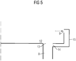
- the drainage system is in Fig. 5 detail. It comprises a collecting trough 12 for collecting water, a drainage pipe 8, which has a first access, which serves as outflow 13 of the collecting trough 12, and it comprises an overflow pipe 15 with an overflow opening 9.
- the collecting trough 12 is in the predetermined installation position of the stand 1 arranged below the motor / generator unit.
- the overflow pipe 15 is connected via a further, second access 14 with the drainage pipe 8.
- the overflow opening 9 is arranged in the predetermined installation position of the framework 1 above the outflow 13 of the collecting trough 12.
- the drainage system can be serviced from the maintenance access, for example, by the drainage pipe 8 and / or the overflow pipe 15 are arranged on the side of the maintenance access in the framework.
- a drainage system is provided in particular when it can not be avoided by the cooling air flow from the outside into the framework, moisture, for example, by rain or snow to enter into the scaffold. Additionally or alternatively, one or more water separators between the ventilation openings and the heat exchanger to be arranged.
Landscapes
- Engineering & Computer Science (AREA)
- Automation & Control Theory (AREA)
- Transportation (AREA)
- Mechanical Engineering (AREA)
- Electric Propulsion And Braking For Vehicles (AREA)
- Motor Or Generator Cooling System (AREA)
Description
- Die Erfindung betrifft ein Gerüst zum Einbau in eine elektrisch angetriebene Lokomotive in einer vorgegebenen Einbaulage, welches zumindest einen Verbrennungsmotor und einen an diesen angeschlossenen Generator umfasst, welche gemeinsam eine Motor-/Generatoreinheit bilden, und welches Gerüst zumindest eine Schnittstelle für eine Kraftstoffzufuhr und zumindest eine Schnittstelle für eine Leistungsabgabe aufweist.
- Solche Gerüste, wie in
Fig. 1 längsgeschnitten veranschaulicht, sind dem Fachmann bekannt, beispielsweise durch das TRAXX F140 AC mit Last Mile Motor, welches ein Kühlungssystem für eine Motor-/Generatoreinheit 2 umfasst, welches zumindest einen Wärmeübertrager 3 aufweist, welcher in der vorgegebenen Einbaulage des Gerüsts 1 in axialer Richtung der Elektrolokomotive fluchtend zur Motor-/Generatoreinheit 2 angeordnet ist, wodurch das Gerüst 1 sehr viel Bauraum in axialer Richtung der Elektrolokomotive einnimmt, was zusätzlich zu einem hohen Gewicht führt. Ein Kühllufteintritt 6 ist oben im Gerüst 1 angeordnet, während ein Kühlluftaustritt 7 nach unten aus dem Gerüst 1 weist und gleichzeitig auch als Restwasseraustritt dient. Die Kühlluft wird daher längs durch das Gerüst 1 geführt. Darüber hinaus ist das Gerüst für eine vorgegebene Elektrolokomotive konzipiert und scheint nicht geeignet zu sein an unterschiedlichen Stellen oder mehrfach in der Elektrolokomotive eingebaut zu werden. - Weitere gattungsgemäße Gerüste sind beispielsweise auch den Druckschriften
US 2009/0101041 A1 ,US 2010/0071585 A1 undEP 1 238 881 A1 zu entnehmen. - Der Erfindung liegt die Aufgabe zugrunde, die Flexibilität zum Einbau eines Gerüsts deutlich zu erhöhen.
- Gelöst wird die Aufgabe durch den Gegenstand des unabhängigen Patentanspruchs 1. Weiterbildungen und Ausgestaltungen der Erfindung finden sich in den Merkmalen der abhängigen Patentansprüche wieder.
- Ein erfindungsgemäßes Schienenfahrzeug, im Besonderen eine Elektrolokomotive des Schienenverkehrs umfasst ein Gerüst zum Einbau in ein elektrisch angetriebenes Schienenfahrzeug, insbesondere in eine Elektrolokomotive, welches Gerüst zumindest einen Verbrennungsmotor, beispielsweise einem Dieselmotor, und zumindest einen an diesen Verbrennungsmotor angeschlossenen Generator zur Stromerzeugung umfasst. Gemeinsam bilden sie eine Motor-/Generatoreinheit. Das Gerüst umfasst zusätzlich mehrere Schnittstellen, darunter zumindest eine Schnittstelle für eine Kraftstoffzufuhr und zumindest eine Schnittstelle für eine Leistungsabgabe, beispielsweise eine elektrische Steckverbindung zum Verbinden eines Stromkabels mit dem Generator. Des Weiteren kann mindestens eine Schnittstelle zur Steuerung zumindest der einen Motor-/Generatoreinheit vorgesehen sein, eine sogenannte Steueranbindung.
- Das Gerüst ist nun erfindungsgemäß so aufgebaut, dass die zumindest eine Schnittstelle für die Kraftstoffzufuhr und die zumindest eine Schnittstelle für die Leistungsabgabe in der vorgegebenen Einbaulage des Gerüsts unterhalb der Motor-/Generatoreinheit angeordnet sind, wobei das Gerüst in der vorgegebenen Einbaulage seitlich einen Wartungszugang aufweist, durch welchen zumindest die Motor-/Generatoreinheit frei zugänglich ist. Insbesondere sind auch die Steueranbindung oder weitere Schnittstellen unterhalb des Motors angeordnet. Sind die Schnittstellen auf der Seite und in dem Bereich des Wartungszugangs des Gerüsts angeordnet, so sind auch sie durch den Wartungszugang frei zugänglich.
- Darüber hinaus ist das Gerüst so im Schienenfahrzeug angeordnet ist, dass der Wartungszugang des Gerüsts von einem Gang des Schienenfahrzeugs aus zugänglich ist. Der Wartungszugang weist daher zum Gang. In speziellerer Art und Weise ist der Wartungszugang ausschließlich vom Gang aus zugänglich.
- Im Allgemeinen sind sämtliche Wartungskomponenten des Gerüsts durch den zumindest einen Wartungszugang austauschbar. Hier beispielsweise ausschließlich durch zumindest einen, auf einer einzigen Seite des Gerüsts angeordneten Wartungszugang, welcher insbesondere vom Gang aus zugänglich ist.
- Eine Variante der Erfindung sieht einen Wartungszugang vor, der von einer Außenseite, insbesondere durch eine Seitenwand des Schienenfahrzeugs von Außen zugänglich ist.
- Eine Weiterbildung der Erfindung ist darin zu sehen, dass die zumindest eine Schnittstelle für die Kraftstoffzufuhr und/oder die zumindest eine Schnittstelle für die Leistungsabgabe in der vorgegebenen Einbaulage des Gerüsts nach unten aus dem Gerüst weisen. Ist eine Schnittstelle beispielsweise als Steckverbindung ausgeführt, so sind Kabel oder Schläuche nach unten aus dem Gerüst herausgeführt. Gemäß einem Ausgestaltungsbeispiel ist genau eine Schnittstelle für die Kraftstoffzufuhr und/oder genau eine Schnittstelle für
die Leistungsabgabe vorgesehen. Weitergebildet weisen die Schnittstellen ausschließlich nach unten aus dem Gerüst. - Gemäß einer weiteren Weiterbildung der erfindungsgemäßen Lösung weist das Gerüst ein Kühlungssystem für die Motor-/Generatoreinheit aus, welches zumindest einen Wärmeübertrager aufweist, welcher in der vorgegebenen Einbaulage des Gerüsts oberhalb der Motor-/Generatoreinheit angeordnet ist. Die Motor-/Generatoreinheit ist zumindest auf der Seite des Wartungszugangs frei vom Wärmeübertrager. Auch der Wärmeübertrager ist gemäß einer Ausführungsform durch den Wartungszugang frei zugänglich. Durch diese Sandwich-Bauweise baut das Gerüst sehr kurz, wodurch die Baugröße des Gerüsts im Vergleich zum Stand der Technik wesentlich verringert ist.
- Weitergebildet umfasst das Gerüst zumindest einen Kühllufteintritt und zumindest einen Kühlluftaustritt, welcher zumindest eine Kühllufteintritt und/oder welcher zumindest eine Kühlluftaustritt in der vorgegebenen Einbaulage des Gerüsts nach oben aus dem Gerüst weisen, um Luft von oben in das Gerüst hinein- oder nach oben aus dem Gerüst herauszuführen. Der zumindest eine Kühllufteintritt und/oder welcher zumindest eine Kühlluftaustritt sind entsprechend oberhalb der Motor-/Generatoreinheit im Gerüst vorgesehen. Insbesondere in der Ausgestaltung mit einem oberhalb der Motor-/Generatoreinheit angeordneten Wärmetauscher sind der Kühllufteintritt und/oder der Kühlluftaustritt oberhalb des Wärmetauschers angeordnet.
- Eine alternative Lösung sieht vor, dass Kühlluft auch aus dem Maschinenraum angesaugt wird, beispielsweise seitlich zur Motor-/Generatoreinheit, also durch einen seitlich angeordneten Kühllufteintritt. Die Abluft kann dann ebenfalls nach oben, also durch einen oberhalb der Motor-/Generatoreinheit angeordneten Kühlluftaustritt ausgeblasen werden.
- In weiteren Weiterbildungen ist ein Drainagesystem im Gerüst vorgesehen, welches eine Sammelwanne zum Auffangen von Wasser umfasst, welche Sammelwanne in der vorgegebenen Einbaulage des Gerüsts unterhalb der Motor-/Generatoreinheit angeordnet ist. Die Sammelwanne weist einen Abfluss und ein daran anschließendes Drainagerohr auf, welches nach unten aus dem Gerüst herausgeführt ist. Der Abfluss dient als erster Zugang zum Drainagerohr. Ein weiterer Zugang kann mit einem Überlaufrohr mit einer Überlauföffnung verbunden sein, welche Überlauföffnung in Einbaulage des Gerüsts oberhalb des Abflusses der Sammelwanne angeordnet ist. Der Überlauf dient der Ableitung von gesammeltem Wasser auch bei einem verstopften Abfluss.
- Gemäß einer Ausführungsform weist das Gerüst ein Kühlsystem mit einem oberhalb der Motor-/Generatoreinheit angeordneten Wärmeübertrager auf. Alternativ kann das Schienenfahrzeug, nachfolgend ist lediglich das Ausführungsbeispiel einer Elektrolokomotive näher erläutert, ein Kühlungssystem für die Motor-/Generatoreinheit umfassen, welches zumindest einen Wärmeübertrager aufweist, welcher auf einem Dach des Schienenfahrzeugs oder Unterflur angeordnet ist. Dies ermöglicht eine noch kompaktere Bauweise des Gerüsts, so dass es in vielen verschieden aufgebauten Lokomotiven einsetzbar ist.
- Die Elektrolokomotive weist eine Aufnahmeeinheit zur Aufnahme jeweils eines Gerüsts auf. Um einen Versatz zwischen Aufnahmeeinheit und Gerüst auszugleichen, ist ein Adapterrahmen vorgesehen. Erfindungsgemäß umfasst die Elektrolokomotive zumindest zwei Lüftungsöffnungen in ihrer Außenhaut, insbesondere im Dach. Der Adapterrahmen ist dann zur Anpassung des Kühllufteintritts und des Kühlluftaustritts des Gerüsts an die Lüftungsöffnungen zwischen dem Gerüst und den Lüftungsöffnungen angeordnet, um Luft zwischen zumindest einer ersten Lüftungsöffnung und dem Kühllufteintritt und zwischen zumindest einer weiteren, zweiten Lüftungsöffnung dem Kühlluftaustritt des Gerüsts zu führen. Der Adapterrahmen umfasst dabei beispielsweise zumindest einen Lüftungskanal zwischen dem zumindest einen Kühllufteintritt und der zumindest einen, ersten Lüftungsöffnung und zumindest einen Lüftungskanal zwischen dem zumindest einen Kühlluftaustritt und der zumindest einen, zweiten Lüftungsöffnung. Die Lüftungsöffnungen sind insbesondere so am Dach angeordnet, dass die Kühlluft seitlich durch eine Dachschräge eintritt und näherungsweise vertikal nach oben aus dem Dach austritt.
- Alternativ umfasst das Schienenfahrzeug, insbesondere die Elektrolokomotive, ein Kühlungssystem für die Motor-/Generatoreinheit, welches zumindest einen Wärmeübertrager aufweist, welcher zwischen einer Seitenwand der Elektrolokomotive und der Motor-/Generatoreinheit angeordnet ist, wobei Luft seitlich angesaugt wird. Die Abluft wird dann ebenfalls seitlich oder über das Dach abgeleitet.
- Neben dem Wärmeübertrager kann das Kühlsystem weiterhin zumindest einen Wasserabscheider zur Trocknung der Kühlluft umfassen, welcher zwischen dem Wärmeübertrager und einer Lüftungsöffnung in der Außenhaut der Elektrolokomotive angeordnet ist, durch welche Kühlluft zum Wärmeübertrager geführt ist. Der Wasserabscheider kann zusätzlich oder alternativ zum Drainagesystem vorgesehen sein. Wird Luft durch den Maschinenraum angesaugt, ist diese meist trocken und daher wird weder ein Wasserabscheider, noch ein Drainagesystem benötigt. Ist der Wärmeübertrager außerhalb des Gerüsts, beispielsweise auf einem Dach des Schienenfahrzeugs oder Unterflur angeordnet, so ist ebenfalls kein Wasserabscheider oder kein Drainagesystem von Nöten.
- Eine weitere Weiterbildung des erfindungsgemäßen Schienenfahrzeugs sieht vor, dass es zumindest zwei zum Gerüst komplementäre Aufnahmeeinheiten zur Aufnahme jeweils eines Gerüsts umfasst, welche jeweils zu den Schnittstellen des Gerüsts komplementäre Schnittstellen aufweisen, welche also jeweils zumindest eine Schnittstelle für eine Kraftstoffzufuhr und zumindest eine Schnittstelle für eine Leistungsabgabe aufweisen. Insbesondere weisen die Aufnahmeeinheiten zusätzlich komplementär ausgebildete Schnittstellen zu den Kühlluftein- und austritten des Gerüsts auf. Durch einheitliche Schnittstellen lässt sich ein Gerüst somit an mehreren Stellen im Schienenfahrzeug positionieren. Dies ermöglicht eine gesteigerte Flexibilität auch bei der Positionierung von anderen Gerüsten in Bezug auf Bauraum und Gewichtsverteilung. Auch sind so zwei erfindungsgemäße Gerüste vorzusehen, um mehr Hilfsaggregateleistung bereitszustellen.
- Gemäß einer weiteren Weiterbildung handelt es sich bei dem Verbrennungsmotor des Gerüsts um einen sogenannten Rangier- oder Hilfsdieselmotor zum Rangieren oder für Kurzstreckenfahrten mit einer maximalen Gesamtdieselleistung der Lokomotive kleiner 500kW. Die elektrische Leistung ist dadurch nicht betroffen. Insbesondere ist die Leistung des Verbrennungsmotors je Gerüst beschränkt auf 400kW.
- Eine weitere Variante ist darin zu sehen, dass eine Elektrolokomotive ein Gerüst als montagefähige Einheit zum Einbau in ein elektrisch angetriebenes Schienenfahrzeug, insbesondere in eine Elektrolokomotive, umfasst, welches Gerüst zumindest zwei, insbesondere jedoch genau zwei Verbrennungsmotoren, beispielsweise Dieselmotoren, und zumindest zwei, insbesondere jedoch genau zwei an die Verbrennungsmotoren angeschlossenen Generatoren zur Stromerzeugung umfasst, wobei jeweils genau ein Generator von genau einem Verbrennungsmotor angetrieben wird, welche somit zumindest zwei, insbesondere jedoch genau zwei voneinander unabhängige Motor-/Generatoreinheiten bilden.
- Die Erfindung lässt zahlreiche Ausführungsformen zu. Sie wird anhand der nachfolgenden Figuren näher erläutert, in denen jeweils ein Ausgestaltungsbeispiel dargestellt ist. Gleiche Elemente in den Figuren sind mit gleichen Bezugszeichen versehen.
- Fig. 1
- zeigt schematisch ein Gerüst des Stands der Technik,
- Fig. 2
- zeigt schematisch ein erfindungsgemäßes Gerüst von einer Seite eines Wartungszugangs,
- Fig. 3
- zeigt schematisch ein erfindungsgemäßes Gerüst von oben,
- Fig. 4
- zeigt schematisch das Gerüst aus
Fig. 3 von vorne, - Fig. 5
- zeigt schematisch ein Drainagesystem des Gerüsts.
- In
Fig. 2 ist ein erfindungsgemäßes Gerüst 1 schematisch dargestellt. Es weist einen Wartungszugang auf, durch welchen die Komponenten des Gerüsts 1 zugänglich sind. Die Komponenten sind eine Motor-/Generatoreinheit 2, ein Wärmeübertrager 3 eines Kühlsystems und Schnittstellen 5 für die Kraftstoffzufuhr des Motors und für die Leistungsabgabe des Generators. Zusätzlich kann eine Steuerungsanbindung in gleicher Lage vorgesehen sein. Das hier skizzierte Gerüst ist in Schichten aufgebaut, oben der Wärmeübertrager 3, in der Mitte die Motor-/Generatoreinheit 2 und unten die Schnittstellen 5 und ein Drainagerohr 8 eines Drainagesystems. Gemäß der hier gezeigten Ausgestaltung ist der Wärmeübertrager 3 ausschließlich oberhalb der Motor-/Generatoreinheit 2 angeordnet und die Schnittstellen 5 sind ausschließlich unterhalb der Motor-/Generatoreinheit 2 angeordnet. Darüber hinaus sind ein Kühllufteintritt 6 und ein Kühlluftaustritt 7 im oberen Bereich des Gerüsts 1 oberhalb des Wärmeübertragers 3 vorgesehen. Kühlluft wird von oben in das Gerüst 1 eingesaugt und die Abluft wird nach oben aus dem Gerüst 1 ausgestoßen, beispielsweise zur Dachebene eines Schienenfahrzeugs, in welchem des Gerüst 1 eingebaut ist, ausgeblasen. Die Schnittstellen 5 sind auf der Seite des Wartungszugangs am unteren Rand des Gerüsts angeordnet, insbesondere nach unten aus dem Gerüst abgehend. Zusätzlich weist das Gerüst ein Drainagesystem mit einem Drainagerohr 8 auf, welches ebenfalls nach unten aus dem Gerüst herausführt. Somit sind sämtliche Komponenten durch den Wartungszugang zugänglich und insbesondere sämtliche Wartungskomponenten durch diesen Wartungszugang austauschbar. -
Fig. 3 offenbart ein, in einer Elektrolokomotive montiertes Gerüst 1 in einer Draufsicht von oben. Die Elektrolokomotive weist einen Gang 11 auf, an welchen das Gerüst 1 mit seinem Wartungszugang 4 angrenzt. Des Weiteren grenzt das Gerüst seitlich an eine Lokkastenwand 10, eine seitliche Außenwandung der Elektrolokomotive. Zwei Nachbargerüste 19 umrahmen schließlich das Gerüst. Die Komponenten 2 und 5 des Gerüsts 1 sind hier durch den Wartungszugang 4 frei zugänglich, insbesondere da die Schnittstellen 5 auf der Seite des Wartungszugangs 4 am unteren Rand des Gerüsts 1 angeordnet sind. Alternativ können sie auf der gegenüberliegenden Seite des Gangs 11 angeordnet sein, so dass sämtliche Wartungskomponenten durch die Lokkastenwand 10 von Außen zugänglich und gegebenenfalls austauschbar sind. - In
Fig. 4 ist das Gerüst ausFig. 3 im Querschnitt durch die Elektrolokomotive dargestellt. Die Elektrolokomotive weist eine einen Lokkasten mit einer Seitenwand 10, einem Dach 20 und einem Boden auf, auf welchem das Gerüst 1 in vorgegebener Einbaulage angeordnet ist. Der Wärmeübertrager 3 ist oberhalb der Motor-/Generatoreinheit 2 im Gerüst 1 angeordnet, die Schnittstellen 5 unterhalb und auf der Seite des Wartungszugangs 4, welcher seinerseits an den Gang 11 der Elektrolokomotive grenzt. Das Gerüst 1 ist hier etwas niedriger als eine in der Elektrolokomotive vorgesehene Aufnahmeeinheit zur Aufnahme des Gerüsts. Daher ist ein Adapterrahmen 18 zwischen Gerüst 1 und Elektrolokomotive vorgesehen. Dieser verbindet hier den Kühllufteintritt 6 und den Kühlluftaustritt 7 im oberen Bereich des Gerüsts 1 mit Lüftungsöffnungen 16, 17 in der Außenhaut der Elektrolokomotive, hier im Dach 20 der Elektrolokomotive. Eine Lüftungsöffnung 16 ist in einer Dachschräge angeordnet und dient der Kühlluftzufuhr, die andere Lüftungsöffnung 17 dient der Abluftabfuhr und ist in einem horizontal verlaufenden Abschnitt des Dachs 20 vorgesehen. Zusätzlich führt wieder ein Drainagerohr 8 Wasser nach unten aus dem Gerüst 1 und aus dem Lokkasten. - Das Drainagesystem ist in
Fig. 5 detailliert. Es umfasst eine Sammelwanne 12 zum Auffangen von Wasser, ein Drainagerohr 8, welches einen ersten Zugang aufweist, welcher als Abfluss 13 der Sammelwanne 12 dient, und es umfasst ein Überlaufrohr 15 mit einer Überlauföffnung 9. Die Sammelwanne 12 ist in der vorgegebenen Einbaulage des Gerüsts 1 unterhalb der Motor-/Generatoreinheit angeordnet. Das Überlaufrohr 15 ist über einen weiteren, zweiten Zugang 14 mit dem Drainagerohr 8 verbunden. Die Überlauföffnung 9 ist in der vorgegebenen Einbaulage des Gerüsts 1 oberhalb des Abflusses 13 der Sammelwanne 12 angeordnet. Auch das Drainagesystem kann vom Wartungszugang aus gewartet werden, indem beispielsweise das Drainagerohr 8 und/oder das Überlaufrohr 15 auf der Seite des Wartungszugangs im Gerüst angeordnet sind. Ein Drainagesystem ist insbesondere dann vorgesehen, wenn durch die Kühlluftführung von Außen in das Gerüst es nicht vermieden werden kann, Feuchtigkeit, beispielsweise durch Regen oder Schnee, in das Gerüst einzutragen. Zusätzlich oder Alternativ sind ein oder mehrere Wasserabscheider zwischen den Lüftungsöffnungen und dem Wärmetauscher anzuordnen.
Claims (13)
- Elektrolokomotive des Schienenverkehrs mit einem Gerüst (1) zum Einbau in ein elektrisch angetriebenes Schienenfahrzeug in einer vorgegebenen Einbaulage, welches Gerüst (1) zumindest einen Verbrennungsmotor und einen an diesen angeschlossenen Generator umfasst, welche gemeinsam eine Motor-/Generatoreinheit (2) bilden, und welches Gerüst (1) zumindest eine Schnittstelle (5) für eine Kraftstoffzufuhr und zumindest eine Schnittstelle (5) für eine Leistungsabgabe aufweist, wobei die Schnittstelle (5) für die Kraftstoffzufuhr und die Schnittstelle (5) für die Leistungsabgabe in der vorgegebenen Einbaulage des Gerüsts (1) unterhalb der Motor-/Generatoreinheit (2) angeordnet sind, und wobei das Gerüst (1) in der vorgegebenen Einbaulage seitlich einen Wartungszugang (4) aufweist, durch welchen zumindest die Motor-/Generatoreinheit (2) frei zugänglich ist, dadurch gekennzeichnet, dass das Gerüst (1) in der vorgegebenen Einbaulage so in der Elektrolokomotive angeordnet ist, dass der Wartungszugang (4) des Gerüsts (1) von einem Gang (11) der Elektrolokomotive aus zugänglich ist, wobei die Elektrolokomotive zumindest zwei Lüftungsöffnungen (16, 17) in ihrer Außenhaut umfasst, wobei zwischen dem Gerüst (1) und den Lüftungsöffnungen (16, 17) ein Adapterrahmen (18) zur Anpassung des Kühllufteintritts (6) und des Kühlluftaustritts (7) des Gerüsts (1) an die Lüftungsöffnungen (16, 17) angeordnet ist, um Luft zwischen zumindest einer ersten Lüftungsöffnung (16) und dem Kühllufteintritt (6) und zwischen zumindest einer weiteren, zweiten Lüftungsöffnung (17) dem Kühlluftaustritt (7) des Gerüsts (1) zu führen.
- Elektrolokomotive nach Anspruch 1, dadurch gekennzeichnet, dass es ein Kühlungssystem für die Motor-/Generatoreinheit (2) umfasst, welches zumindest einen Wärmeübertrager (3) aufweist, welcher in der vorgegebenen Einbaulage des Gerüsts (1) oberhalb der Motor-/Generatoreinheit (2) angeordnet ist.
- Elektrolokomotive nach einem der Ansprüche 1 oder 2, dadurch gekennzeichnet, dass die Schnittstelle (5) für die Kraftstoffzufuhr und/oder die Schnittstelle (5) für die Leistungsabgabe in der vorgegebenen Einbaulage des Gerüsts (1) nach unten aus dem Gerüst weisen.
- Elektrolokomotive nach einem der Ansprüche 1 bis 3, dadurch gekennzeichnet, dass die Schnittstelle (5) für die Kraftstoffzufuhr und/oder die Schnittstelle (5) für die Leistungsabgabe in der vorgegebenen Einbaulage des Gerüsts auf der Seite und in dem Bereich des Wartungszugangs (4) des Gerüsts (1) angeordnet sind.
- Elektrolokomotive nach einem der Ansprüche 1 bis 4, dadurch gekennzeichnet, dass es zumindest einen Kühllufteintritt (6) und zumindest einen Kühlluftaustritt (7) aufweist, welcher Kühllufteintritt (6) und/oder welcher Kühlluftaustritt (7) in der vorgegebenen Einbaulage des Gerüsts (1) nach oben aus dem Gerüst (1) weisen.
- Elektrolokomotive nach einem der Ansprüche 1 bis 5, dadurch gekennzeichnet, dass es ein Drainagesystem mit einer Sammelwanne zum Auffangen von Wasser und ein Drainagerohr (8) umfasst, welche Sammelwanne (12) in Einbaulage des Gerüsts (1) unterhalb der Motor-/Generatoreinheit angeordnet ist, und welches Drainagerohr (8) an einen Abfluss (13) der Sammelwanne (12) angeschlossen ist und nach unten aus dem Gerüst (1) weist, um Wasser nach unten aus dem Gerüst (1) herauszuführen.
- Elektrolokomotive nach Anspruch 6, dadurch gekennzeichnet, dass das Drainagerohr (8) einen weiteren Zugang (14) aufweist, welcher mit einem Überlaufrohr (15) mit einer Überlauföffnung (9) verbunden ist, welche Überlauföffnung (9) in Einbaulage des Gerüsts (1) oberhalb des Abflusses (13) der Sammelwanne (12) angeordnet ist.
- Elektrolokomotive nach einem der Ansprüche 1 bis 7, dadurch gekennzeichnet, dass sie ein Kühlungssystem für die Motor-/Generatoreinheit (2) umfasst, welches zumindest einen Wärmeübertrager (3) aufweist, welcher auf einem Dach der Elektrolokomotive oder Unterflur angeordnet ist.
- Elektrolokomotive nach einem der Ansprüche 1 bis 8, dadurch gekennzeichnet, dass sie zumindest zwei zum Gerüst komplementäre Aufnahmeeinheiten zur Aufnahme jeweils eines Gerüsts umfasst, welche jeweils zu den Schnittstellen des Gerüsts komplementäre Schnittstellen aufweisen.
- Elektrolokomotive nach einem der Ansprüche 1 bis 9, dadurch gekennzeichnet, dass sie zumindest ein Kühlungssystem für die Motor-/Generatoreinheit umfasst, welches zumindest einen Wärmeübertrager aufweist, und dass sie zumindest einen Wasserabscheider zur Trocknung der Kühlluft umfasst, welcher zwischen dem Wärmeübertrager und einer Lüftungsöffnung in der Außenhaut der Elektrolokomotive angeordnet ist, durch welche Kühlluft zum Wärmeübertrager geführt ist.
- Elektrolokomotive nach Anspruch 1, dadurch gekennzeichnet, dass sie ein Kühlungssystem für die Motor-/Generatoreinheit umfasst, welches zumindest einen Wärmeübertrager aufweist, welcher zwischen einer Seitenwand der Elektrolokomotive und der Motor-/Generatoreinheit angeordnet ist, wobei Luft seitlich angesaugt wird.
- Elektrolokomotive nach Anspruch 1, dadurch gekennzeichnet, dass sämtliche Wartungskomponenten des Gerüsts vom Gang aus austauschbar sind.
- Elektrolokomotive nach einem der Ansprüche 1 bis 12, dadurch gekennzeichnet, dass die maximal in der Elektrolokomotive installierte Verbrennungsmotorleistung kleiner 500kW ist.
Priority Applications (1)
| Application Number | Priority Date | Filing Date | Title |
|---|---|---|---|
| PL13753839T PL2879932T3 (pl) | 2012-09-17 | 2013-08-16 | Szkielet konstrukcji agregatów pomocniczych dla lokomotywy elektrycznej |
Applications Claiming Priority (2)
| Application Number | Priority Date | Filing Date | Title |
|---|---|---|---|
| DE102012018245.7A DE102012018245A1 (de) | 2012-09-17 | 2012-09-17 | Hilfsaggregategerüst für eine Elektrolokomotive |
| PCT/EP2013/067115 WO2014040820A1 (de) | 2012-09-17 | 2013-08-16 | Hilfsaggregategerüst für eine elektrolokomotive |
Publications (2)
| Publication Number | Publication Date |
|---|---|
| EP2879932A1 EP2879932A1 (de) | 2015-06-10 |
| EP2879932B1 true EP2879932B1 (de) | 2017-09-27 |
Family
ID=49083652
Family Applications (1)
| Application Number | Title | Priority Date | Filing Date |
|---|---|---|---|
| EP13753839.3A Active EP2879932B1 (de) | 2012-09-17 | 2013-08-16 | Hilfsaggregategerüst für eine elektrolokomotive |
Country Status (5)
| Country | Link |
|---|---|
| EP (1) | EP2879932B1 (de) |
| DE (1) | DE102012018245A1 (de) |
| ES (1) | ES2654672T3 (de) |
| PL (1) | PL2879932T3 (de) |
| WO (1) | WO2014040820A1 (de) |
Family Cites Families (8)
| Publication number | Priority date | Publication date | Assignee | Title |
|---|---|---|---|---|
| GB314107A (en) * | 1928-03-21 | 1929-06-21 | Robert Brooks | Improvements in electric locomotives |
| DE20002814U1 (de) * | 2000-02-16 | 2000-04-20 | DWA Deutsche Waggonbau GmbH, 12526 Berlin | Doppelstöckiges Schienenfahrzeug |
| DE10110424A1 (de) * | 2001-03-05 | 2002-09-12 | Siemens Duewag Gmbh | Angetriebenes Schienenfahrzeug, insbesondere für die Personenbeförderung im Nah- und Regionalverkehr |
| DE10145237A1 (de) * | 2001-09-13 | 2003-04-03 | Bombardier Transp Gmbh | Lokomotive mit Seitengängen |
| DE202005015144U1 (de) * | 2005-09-26 | 2005-12-01 | Evoinvent Ag | Lokomotive |
| US20090101041A1 (en) * | 2007-06-20 | 2009-04-23 | Railpower Technologies Corp. | Transversal generator set and modular design for refurbishment of locomotives |
| US8196521B2 (en) * | 2008-09-19 | 2012-06-12 | Progress Rail Services Corp | Locomotive power module installation and removal |
| JP5563851B2 (ja) * | 2010-03-05 | 2014-07-30 | 株式会社東芝 | ハイブリッド機関車 |
-
2012
- 2012-09-17 DE DE102012018245.7A patent/DE102012018245A1/de not_active Withdrawn
-
2013
- 2013-08-16 PL PL13753839T patent/PL2879932T3/pl unknown
- 2013-08-16 EP EP13753839.3A patent/EP2879932B1/de active Active
- 2013-08-16 ES ES13753839.3T patent/ES2654672T3/es active Active
- 2013-08-16 WO PCT/EP2013/067115 patent/WO2014040820A1/de not_active Ceased
Non-Patent Citations (1)
| Title |
|---|
| None * |
Also Published As
| Publication number | Publication date |
|---|---|
| DE102012018245A1 (de) | 2014-03-20 |
| WO2014040820A1 (de) | 2014-03-20 |
| ES2654672T3 (es) | 2018-02-14 |
| PL2879932T3 (pl) | 2018-02-28 |
| EP2879932A1 (de) | 2015-06-10 |
Similar Documents
| Publication | Publication Date | Title |
|---|---|---|
| EP2242672B2 (de) | Modulares bremsgerüst | |
| EP2038154B1 (de) | Schienenfahrzeug mit einer kühlanordnung für in einem unterflurbereich angeordnete komponenten | |
| DE102012005902B4 (de) | Hochspannungskabel-Führungsstruktur für ein elektrisch angetriebenes Fahrzeug | |
| EP3341237B1 (de) | Bodenstation zum induktiven laden eines kraftfahrzeugs | |
| EP2318251B1 (de) | Schienenfahrzeug mit umschaltung zwischen winter- und sommerbetrieb | |
| DE102007059706A1 (de) | Montageeinheit | |
| EP3265358B2 (de) | Schienenfahrzeug, verfahren zum antreiben eines schienenfahrzeugs sowie verfahren zur herstellung eines schienenfahrzeugs | |
| DE102022131169B4 (de) | Ladestation mit einer Luftführungsvorrichtung und einer Klimatisierungsvorrichtung | |
| DE102011114354B3 (de) | Unterflurkühlanlage für ein Schienenfahrzeug | |
| EP2879932B1 (de) | Hilfsaggregategerüst für eine elektrolokomotive | |
| EP1086313A1 (de) | Wartungsvorrichtung für druckluftanlagen | |
| EP2000384A1 (de) | Bühnenloser Service-Arbeitsstand für ein Schienenfahrzeug | |
| EP2021222B1 (de) | Montageeinheit für ein schienen-triebfahrzeug | |
| EP3150847A1 (de) | Windkraftmodul für eine windkraftanlage | |
| DE102009037465A1 (de) | Stromverteilungsarchitektur für ein Luftfahrzeug | |
| EP2845781A1 (de) | Schienenfahrzeug mit Bremswiderstandsgehäuse | |
| DE102015110294A1 (de) | Sanitäreinrichtung, insbesondere Dusch-WC oder elektronisches Bidet | |
| DE102014005731A1 (de) | Aggregateraumabdeckung für einen Kraftwagen | |
| DE102023001188A1 (de) | Kondenswasserablaufsystem eines Fahrzeugs | |
| EP2282152A2 (de) | Nasskühlturm | |
| DE1838747U (de) | Fahrzeugkasten fuer schienentriebfahrzeuge, insbesondere fuer elektrische lokomotiven. | |
| WO2024062066A1 (de) | Elektrischer versorgungsstrang für ein kraftfahrzeug | |
| AT217081B (de) | Belüfteter Fahrzeugtunnel | |
| EP3282060B1 (de) | Transportcontainer | |
| DE102015014646A1 (de) | Wasserkastenabdeckung für ein Kraftfahrzeug |
Legal Events
| Date | Code | Title | Description |
|---|---|---|---|
| PUAI | Public reference made under article 153(3) epc to a published international application that has entered the european phase |
Free format text: ORIGINAL CODE: 0009012 |
|
| 17P | Request for examination filed |
Effective date: 20150304 |
|
| AK | Designated contracting states |
Kind code of ref document: A1 Designated state(s): AL AT BE BG CH CY CZ DE DK EE ES FI FR GB GR HR HU IE IS IT LI LT LU LV MC MK MT NL NO PL PT RO RS SE SI SK SM TR |
|
| AX | Request for extension of the european patent |
Extension state: BA ME |
|
| DAX | Request for extension of the european patent (deleted) | ||
| GRAP | Despatch of communication of intention to grant a patent |
Free format text: ORIGINAL CODE: EPIDOSNIGR1 |
|
| INTG | Intention to grant announced |
Effective date: 20170425 |
|
| GRAS | Grant fee paid |
Free format text: ORIGINAL CODE: EPIDOSNIGR3 |
|
| GRAA | (expected) grant |
Free format text: ORIGINAL CODE: 0009210 |
|
| RAP1 | Party data changed (applicant data changed or rights of an application transferred) |
Owner name: SIEMENS AKTIENGESELLSCHAFT |
|
| AK | Designated contracting states |
Kind code of ref document: B1 Designated state(s): AL AT BE BG CH CY CZ DE DK EE ES FI FR GB GR HR HU IE IS IT LI LT LU LV MC MK MT NL NO PL PT RO RS SE SI SK SM TR |
|
| REG | Reference to a national code |
Ref country code: GB Ref legal event code: FG4D Free format text: NOT ENGLISH |
|
| REG | Reference to a national code |
Ref country code: CH Ref legal event code: EP |
|
| REG | Reference to a national code |
Ref country code: AT Ref legal event code: REF Ref document number: 931653 Country of ref document: AT Kind code of ref document: T Effective date: 20171015 |
|
| REG | Reference to a national code |
Ref country code: IE Ref legal event code: FG4D Free format text: LANGUAGE OF EP DOCUMENT: GERMAN |
|
| REG | Reference to a national code |
Ref country code: DE Ref legal event code: R096 Ref document number: 502013008451 Country of ref document: DE |
|
| PG25 | Lapsed in a contracting state [announced via postgrant information from national office to epo] |
Ref country code: NO Free format text: LAPSE BECAUSE OF FAILURE TO SUBMIT A TRANSLATION OF THE DESCRIPTION OR TO PAY THE FEE WITHIN THE PRESCRIBED TIME-LIMIT Effective date: 20171227 Ref country code: LT Free format text: LAPSE BECAUSE OF FAILURE TO SUBMIT A TRANSLATION OF THE DESCRIPTION OR TO PAY THE FEE WITHIN THE PRESCRIBED TIME-LIMIT Effective date: 20170927 Ref country code: HR Free format text: LAPSE BECAUSE OF FAILURE TO SUBMIT A TRANSLATION OF THE DESCRIPTION OR TO PAY THE FEE WITHIN THE PRESCRIBED TIME-LIMIT Effective date: 20170927 Ref country code: SE Free format text: LAPSE BECAUSE OF FAILURE TO SUBMIT A TRANSLATION OF THE DESCRIPTION OR TO PAY THE FEE WITHIN THE PRESCRIBED TIME-LIMIT Effective date: 20170927 |
|
| REG | Reference to a national code |
Ref country code: NL Ref legal event code: MP Effective date: 20170927 |
|
| REG | Reference to a national code |
Ref country code: LT Ref legal event code: MG4D |
|
| REG | Reference to a national code |
Ref country code: ES Ref legal event code: FG2A Ref document number: 2654672 Country of ref document: ES Kind code of ref document: T3 Effective date: 20180214 |
|
| PG25 | Lapsed in a contracting state [announced via postgrant information from national office to epo] |
Ref country code: GR Free format text: LAPSE BECAUSE OF FAILURE TO SUBMIT A TRANSLATION OF THE DESCRIPTION OR TO PAY THE FEE WITHIN THE PRESCRIBED TIME-LIMIT Effective date: 20171228 Ref country code: RS Free format text: LAPSE BECAUSE OF FAILURE TO SUBMIT A TRANSLATION OF THE DESCRIPTION OR TO PAY THE FEE WITHIN THE PRESCRIBED TIME-LIMIT Effective date: 20170927 Ref country code: BG Free format text: LAPSE BECAUSE OF FAILURE TO SUBMIT A TRANSLATION OF THE DESCRIPTION OR TO PAY THE FEE WITHIN THE PRESCRIBED TIME-LIMIT Effective date: 20171227 Ref country code: LV Free format text: LAPSE BECAUSE OF FAILURE TO SUBMIT A TRANSLATION OF THE DESCRIPTION OR TO PAY THE FEE WITHIN THE PRESCRIBED TIME-LIMIT Effective date: 20170927 |
|
| PG25 | Lapsed in a contracting state [announced via postgrant information from national office to epo] |
Ref country code: NL Free format text: LAPSE BECAUSE OF FAILURE TO SUBMIT A TRANSLATION OF THE DESCRIPTION OR TO PAY THE FEE WITHIN THE PRESCRIBED TIME-LIMIT Effective date: 20170927 |
|
| PG25 | Lapsed in a contracting state [announced via postgrant information from national office to epo] |
Ref country code: RO Free format text: LAPSE BECAUSE OF FAILURE TO SUBMIT A TRANSLATION OF THE DESCRIPTION OR TO PAY THE FEE WITHIN THE PRESCRIBED TIME-LIMIT Effective date: 20170927 |
|
| PG25 | Lapsed in a contracting state [announced via postgrant information from national office to epo] |
Ref country code: IS Free format text: LAPSE BECAUSE OF FAILURE TO SUBMIT A TRANSLATION OF THE DESCRIPTION OR TO PAY THE FEE WITHIN THE PRESCRIBED TIME-LIMIT Effective date: 20180127 Ref country code: SK Free format text: LAPSE BECAUSE OF FAILURE TO SUBMIT A TRANSLATION OF THE DESCRIPTION OR TO PAY THE FEE WITHIN THE PRESCRIBED TIME-LIMIT Effective date: 20170927 Ref country code: EE Free format text: LAPSE BECAUSE OF FAILURE TO SUBMIT A TRANSLATION OF THE DESCRIPTION OR TO PAY THE FEE WITHIN THE PRESCRIBED TIME-LIMIT Effective date: 20170927 Ref country code: SM Free format text: LAPSE BECAUSE OF FAILURE TO SUBMIT A TRANSLATION OF THE DESCRIPTION OR TO PAY THE FEE WITHIN THE PRESCRIBED TIME-LIMIT Effective date: 20170927 |
|
| REG | Reference to a national code |
Ref country code: DE Ref legal event code: R097 Ref document number: 502013008451 Country of ref document: DE |
|
| PG25 | Lapsed in a contracting state [announced via postgrant information from national office to epo] |
Ref country code: DK Free format text: LAPSE BECAUSE OF FAILURE TO SUBMIT A TRANSLATION OF THE DESCRIPTION OR TO PAY THE FEE WITHIN THE PRESCRIBED TIME-LIMIT Effective date: 20170927 |
|
| PLBE | No opposition filed within time limit |
Free format text: ORIGINAL CODE: 0009261 |
|
| STAA | Information on the status of an ep patent application or granted ep patent |
Free format text: STATUS: NO OPPOSITION FILED WITHIN TIME LIMIT |
|
| REG | Reference to a national code |
Ref country code: FR Ref legal event code: PLFP Year of fee payment: 6 |
|
| 26N | No opposition filed |
Effective date: 20180628 |
|
| PG25 | Lapsed in a contracting state [announced via postgrant information from national office to epo] |
Ref country code: MT Free format text: LAPSE BECAUSE OF FAILURE TO SUBMIT A TRANSLATION OF THE DESCRIPTION OR TO PAY THE FEE WITHIN THE PRESCRIBED TIME-LIMIT Effective date: 20170927 |
|
| PGFP | Annual fee paid to national office [announced via postgrant information from national office to epo] |
Ref country code: FR Payment date: 20180827 Year of fee payment: 13 |
|
| PG25 | Lapsed in a contracting state [announced via postgrant information from national office to epo] |
Ref country code: SI Free format text: LAPSE BECAUSE OF FAILURE TO SUBMIT A TRANSLATION OF THE DESCRIPTION OR TO PAY THE FEE WITHIN THE PRESCRIBED TIME-LIMIT Effective date: 20170927 |
|
| REG | Reference to a national code |
Ref country code: DE Ref legal event code: R081 Ref document number: 502013008451 Country of ref document: DE Owner name: SIEMENS MOBILITY GMBH, DE Free format text: FORMER OWNER: SIEMENS AKTIENGESELLSCHAFT, 80333 MUENCHEN, DE |
|
| REG | Reference to a national code |
Ref country code: CH Ref legal event code: PUE Owner name: SIEMENS MOBILITY GMBH, DE Free format text: FORMER OWNER: SIEMENS AKTIENGESELLSCHAFT, DE |
|
| PG25 | Lapsed in a contracting state [announced via postgrant information from national office to epo] |
Ref country code: MC Free format text: LAPSE BECAUSE OF FAILURE TO SUBMIT A TRANSLATION OF THE DESCRIPTION OR TO PAY THE FEE WITHIN THE PRESCRIBED TIME-LIMIT Effective date: 20170927 |
|
| GBPC | Gb: european patent ceased through non-payment of renewal fee |
Effective date: 20180816 |
|
| PG25 | Lapsed in a contracting state [announced via postgrant information from national office to epo] |
Ref country code: LU Free format text: LAPSE BECAUSE OF NON-PAYMENT OF DUE FEES Effective date: 20180816 |
|
| REG | Reference to a national code |
Ref country code: BE Ref legal event code: MM Effective date: 20180831 |
|
| REG | Reference to a national code |
Ref country code: IE Ref legal event code: MM4A |
|
| REG | Reference to a national code |
Ref country code: AT Ref legal event code: PC Ref document number: 931653 Country of ref document: AT Kind code of ref document: T Owner name: SIEMENS MOBILITY GMBH, DE Effective date: 20190506 |
|
| PG25 | Lapsed in a contracting state [announced via postgrant information from national office to epo] |
Ref country code: IE Free format text: LAPSE BECAUSE OF NON-PAYMENT OF DUE FEES Effective date: 20180816 |
|
| PG25 | Lapsed in a contracting state [announced via postgrant information from national office to epo] |
Ref country code: BE Free format text: LAPSE BECAUSE OF NON-PAYMENT OF DUE FEES Effective date: 20180831 |
|
| PG25 | Lapsed in a contracting state [announced via postgrant information from national office to epo] |
Ref country code: GB Free format text: LAPSE BECAUSE OF NON-PAYMENT OF DUE FEES Effective date: 20180816 |
|
| PGFP | Annual fee paid to national office [announced via postgrant information from national office to epo] |
Ref country code: PL Payment date: 20190723 Year of fee payment: 7 |
|
| PG25 | Lapsed in a contracting state [announced via postgrant information from national office to epo] |
Ref country code: TR Free format text: LAPSE BECAUSE OF FAILURE TO SUBMIT A TRANSLATION OF THE DESCRIPTION OR TO PAY THE FEE WITHIN THE PRESCRIBED TIME-LIMIT Effective date: 20170927 |
|
| PG25 | Lapsed in a contracting state [announced via postgrant information from national office to epo] |
Ref country code: PT Free format text: LAPSE BECAUSE OF FAILURE TO SUBMIT A TRANSLATION OF THE DESCRIPTION OR TO PAY THE FEE WITHIN THE PRESCRIBED TIME-LIMIT Effective date: 20170927 Ref country code: HU Free format text: LAPSE BECAUSE OF FAILURE TO SUBMIT A TRANSLATION OF THE DESCRIPTION OR TO PAY THE FEE WITHIN THE PRESCRIBED TIME-LIMIT; INVALID AB INITIO Effective date: 20130816 |
|
| PG25 | Lapsed in a contracting state [announced via postgrant information from national office to epo] |
Ref country code: MK Free format text: LAPSE BECAUSE OF NON-PAYMENT OF DUE FEES Effective date: 20170927 Ref country code: CY Free format text: LAPSE BECAUSE OF FAILURE TO SUBMIT A TRANSLATION OF THE DESCRIPTION OR TO PAY THE FEE WITHIN THE PRESCRIBED TIME-LIMIT Effective date: 20170927 |
|
| PG25 | Lapsed in a contracting state [announced via postgrant information from national office to epo] |
Ref country code: AL Free format text: LAPSE BECAUSE OF FAILURE TO SUBMIT A TRANSLATION OF THE DESCRIPTION OR TO PAY THE FEE WITHIN THE PRESCRIBED TIME-LIMIT Effective date: 20170927 Ref country code: FR Free format text: LAPSE BECAUSE OF NON-PAYMENT OF DUE FEES Effective date: 20190831 |
|
| REG | Reference to a national code |
Ref country code: ES Ref legal event code: PC2A Owner name: SIEMENS MOBILITY GMBH Effective date: 20200805 |
|
| PG25 | Lapsed in a contracting state [announced via postgrant information from national office to epo] |
Ref country code: PL Free format text: LAPSE BECAUSE OF NON-PAYMENT OF DUE FEES Effective date: 20200816 |
|
| PGFP | Annual fee paid to national office [announced via postgrant information from national office to epo] |
Ref country code: IT Payment date: 20230828 Year of fee payment: 11 Ref country code: FI Payment date: 20230821 Year of fee payment: 11 Ref country code: CZ Payment date: 20230807 Year of fee payment: 11 Ref country code: AT Payment date: 20230713 Year of fee payment: 11 |
|
| PGFP | Annual fee paid to national office [announced via postgrant information from national office to epo] |
Ref country code: ES Payment date: 20231124 Year of fee payment: 11 |
|
| PGFP | Annual fee paid to national office [announced via postgrant information from national office to epo] |
Ref country code: DE Payment date: 20231019 Year of fee payment: 11 Ref country code: CH Payment date: 20231114 Year of fee payment: 11 |
|
| REG | Reference to a national code |
Ref country code: DE Ref legal event code: R119 Ref document number: 502013008451 Country of ref document: DE |
|
| REG | Reference to a national code |
Ref country code: CH Ref legal event code: PL |
|
| PG25 | Lapsed in a contracting state [announced via postgrant information from national office to epo] |
Ref country code: FI Free format text: LAPSE BECAUSE OF NON-PAYMENT OF DUE FEES Effective date: 20240816 |
|
| REG | Reference to a national code |
Ref country code: AT Ref legal event code: MM01 Ref document number: 931653 Country of ref document: AT Kind code of ref document: T Effective date: 20240816 |
|
| PG25 | Lapsed in a contracting state [announced via postgrant information from national office to epo] |
Ref country code: AT Free format text: LAPSE BECAUSE OF NON-PAYMENT OF DUE FEES Effective date: 20240816 Ref country code: CH Free format text: LAPSE BECAUSE OF NON-PAYMENT OF DUE FEES Effective date: 20240831 |
|
| PG25 | Lapsed in a contracting state [announced via postgrant information from national office to epo] |
Ref country code: CZ Free format text: LAPSE BECAUSE OF NON-PAYMENT OF DUE FEES Effective date: 20240816 |
|
| PG25 | Lapsed in a contracting state [announced via postgrant information from national office to epo] |
Ref country code: DE Free format text: LAPSE BECAUSE OF NON-PAYMENT OF DUE FEES Effective date: 20250301 |
|
| PG25 | Lapsed in a contracting state [announced via postgrant information from national office to epo] |
Ref country code: IT Free format text: LAPSE BECAUSE OF NON-PAYMENT OF DUE FEES Effective date: 20240816 |
|
| REG | Reference to a national code |
Ref country code: ES Ref legal event code: FD2A Effective date: 20250930 |
|
| PG25 | Lapsed in a contracting state [announced via postgrant information from national office to epo] |
Ref country code: ES Free format text: LAPSE BECAUSE OF NON-PAYMENT OF DUE FEES Effective date: 20240817 |