EP2879939B1 - Verfahren zur unterstützung eines fahrers eines fahrzeugs - Google Patents
Verfahren zur unterstützung eines fahrers eines fahrzeugs Download PDFInfo
- Publication number
- EP2879939B1 EP2879939B1 EP13742192.1A EP13742192A EP2879939B1 EP 2879939 B1 EP2879939 B1 EP 2879939B1 EP 13742192 A EP13742192 A EP 13742192A EP 2879939 B1 EP2879939 B1 EP 2879939B1
- Authority
- EP
- European Patent Office
- Prior art keywords
- vehicle
- driver
- distance
- obstacle
- assistance system
- Prior art date
- Legal status (The legal status is an assumption and is not a legal conclusion. Google has not performed a legal analysis and makes no representation as to the accuracy of the status listed.)
- Not-in-force
Links
Images


Classifications
-
- B—PERFORMING OPERATIONS; TRANSPORTING
- B62—LAND VEHICLES FOR TRAVELLING OTHERWISE THAN ON RAILS
- B62D—MOTOR VEHICLES; TRAILERS
- B62D15/00—Steering not otherwise provided for
- B62D15/02—Steering position indicators ; Steering position determination; Steering aids
- B62D15/027—Parking aids, e.g. instruction means
- B62D15/0285—Parking performed automatically
-
- B—PERFORMING OPERATIONS; TRANSPORTING
- B60—VEHICLES IN GENERAL
- B60Q—ARRANGEMENT OF SIGNALLING OR LIGHTING DEVICES, THE MOUNTING OR SUPPORTING THEREOF OR CIRCUITS THEREFOR, FOR VEHICLES IN GENERAL
- B60Q9/00—Arrangement or adaptation of signal devices not provided for in one of main groups B60Q1/00 - B60Q7/00, e.g. haptic signalling
- B60Q9/002—Arrangement or adaptation of signal devices not provided for in one of main groups B60Q1/00 - B60Q7/00, e.g. haptic signalling for parking purposes, e.g. for warning the driver that his vehicle has contacted or is about to contact an obstacle
- B60Q9/004—Arrangement or adaptation of signal devices not provided for in one of main groups B60Q1/00 - B60Q7/00, e.g. haptic signalling for parking purposes, e.g. for warning the driver that his vehicle has contacted or is about to contact an obstacle using wave sensors
- B60Q9/006—Arrangement or adaptation of signal devices not provided for in one of main groups B60Q1/00 - B60Q7/00, e.g. haptic signalling for parking purposes, e.g. for warning the driver that his vehicle has contacted or is about to contact an obstacle using wave sensors using a distance sensor
-
- B—PERFORMING OPERATIONS; TRANSPORTING
- B60—VEHICLES IN GENERAL
- B60Q—ARRANGEMENT OF SIGNALLING OR LIGHTING DEVICES, THE MOUNTING OR SUPPORTING THEREOF OR CIRCUITS THEREFOR, FOR VEHICLES IN GENERAL
- B60Q9/00—Arrangement or adaptation of signal devices not provided for in one of main groups B60Q1/00 - B60Q7/00, e.g. haptic signalling
- B60Q9/002—Arrangement or adaptation of signal devices not provided for in one of main groups B60Q1/00 - B60Q7/00, e.g. haptic signalling for parking purposes, e.g. for warning the driver that his vehicle has contacted or is about to contact an obstacle
- B60Q9/007—Arrangement or adaptation of signal devices not provided for in one of main groups B60Q1/00 - B60Q7/00, e.g. haptic signalling for parking purposes, e.g. for warning the driver that his vehicle has contacted or is about to contact an obstacle providing information about the distance to an obstacle, e.g. varying sound
Definitions
- the invention relates to a method for assisting a driver of a vehicle, wherein the vehicle comprises a distance warning system, which signals the driver a distance to an obstacle in the vicinity of the vehicle, and a driver assistance system, which controls the lateral guidance in a driving maneuver, and a device for Implementation of the procedure.
- Assistance systems for assisting a driver of a vehicle in a driving maneuver are increasingly being installed in modern vehicles. These driver assistance systems include, for example, distance warning systems that detect obstacles in the surroundings of the vehicle and warn the driver if they fall short of a minimum distance. Furthermore, these driver assistance systems are also used to assist the driver when entering and leaving the vehicle. Depending on the embodiment of the assistance system, the driver is assisted not only by instructions, but also by steering interventions and / or braking interventions, so that the driver's activity is limited to the control of the driving maneuver and acceleration and braking after activation of the assistance system.
- a method for assisting a driver in a parking maneuver is known.
- the environment of the vehicle is measured with sensors and in the presence of a sufficiently large parking space, the driver is offered a supported parking.
- the assistance system determines the optimum parking strategy and provides steering instructions via the visual display device of a distance warning system already in the vehicle.
- the optical display is designed here as a bar graph, via which the driver can read the deviation of the actual steering angle from the requested target steering angle. If required, an acoustic output of the steering instructions can be made.
- DE 10 2008 020 561 A1 describes a method and a device in which the driver both a still to be traveled route, as well as a distance to an obstacle can be signaled.
- the device comprises means for measuring the distance between a vehicle and a point and a visual display in the form of a progress bar for representing this distance.
- the point at which the distance is determined can be, for example, an obstacle, a limitation of a parking space or a point at which a change of direction should take place for optimal parking.
- An acoustic signaling of the distance information is not described.
- a driver assistance system which signals a driver when parking instructions in the form of sounds or visual displays.
- the driver is informed of the remaining distance to a breakpoint via various audio signals.
- a special signal is given to the driver, depending on his reaction speed, shortly before reaching a stop point, so that the vehicle comes to a standstill at the defined point.
- the desired steering direction can also be displayed via acoustic signals.
- EP 2 581 272 A1 discloses a method for assisting a driver of a vehicle, wherein the vehicle comprises a distance warning system, which signals the driver to a distance to an obstacle in the vicinity of the vehicle, and a driving assistance system, which controls the lateral guidance in a driving maneuver, wherein the driver longitudinal guidance hints of Driver assistance system via a signaling device of the distance warning system are displayed.
- a method for assisting a driver of a vehicle wherein the vehicle comprises a distance warning system, which signals the driver a distance to an obstacle in the surroundings of the vehicle, and a driver assistance system, which controls the lateral guidance in a driving maneuver, wherein the driver Longitudinal guidance information of the driver assistance system via a signaling device of the distance warning system are displayed.
- the distance warning system and the driver assistance system can be embodied in a common system or as independent but interconnected systems.
- the common system or the two independent systems have sensors that detect objects in the vicinity of the vehicle and the distance warning system includes a signaling device with which a distance to an object in the vicinity of the vehicle can be displayed. If the two systems are designed independently of one another, each system comprises its own control unit, with both control units being connected to the signaling device of the distance warning system. If the distance warning system and the driving assistance system are implemented together as a common system, the system comprises a single control unit, which implements both functionalities.
- the driver assistance system is set up to control the transverse guidance in a supported driving maneuver, for example via a connection of the control unit to a power steering, the acceleration and braking of the vehicle is the responsibility of the driver of the vehicle.
- the driver assistance system gives the driver longitudinal guidance information about the signaling device of the distance warning system.
- the driver assistance system can apply a braking intervention when a predetermined maximum speed is exceeded and / or falls below a minimum distance to an object in the surroundings of the vehicle.
- the driver is notified of the longitudinal guidance indications in the form of a distance of the vehicle to a point where a direction of travel change is to be made or the vehicle is to be stopped.
- the driver assistance system for displaying the distance to the point where a direction change is to be made or the vehicle is to be stopped generates a virtual obstacle which is signaled by the distance warning system as an actual obstacle.
- the reaction speed and the vehicle speed can be taken into account, and the distance of the virtual obstacle to the vehicle can be assigned an offset or factor. This ensures that the longitudinal guidance information of the driver assistance system are given in time and the vehicle is stopped even at high speed or slow reaction of the driver at the scheduled point.
- This offset which is formed from the vehicle speed and the driver's reaction speed, can also be calmed by means of filters or a hysteresis function so that speed changes do not lead to a sudden change in the distance display.
- the direction in which an obstacle is located is additionally displayed. This makes it possible for the driver when parking, for example, to estimate whether the next parking train in the forward or reverse direction.
- the display of the longitudinal guidance information is audible, wherein the distance to an obstacle over different tones and / or sound sequences is displayed. It is conceivable to display the distance, for example, on the pitch, for example, lower tones signal a greater distance than high tones, and / or a tone sequence, in the short distances between the Tones show a short distance and long intervals between tones indicate a longer distance.
- the display of the longitudinal guidance indications is carried out optically, the distance to an obstacle being displayed over a plurality of illuminated displays and / or via a bar display.
- the display can be implemented, for example, via a plurality of light-emitting diodes, the distance being displayed via the number and / or the color of the activated light-emitting diodes. If there is a screen in the vehicle, for example for a navigation system, then this can also be used to display the distance via a progress bar.
- the signaling device is signaled by a minimum formation of the shortest distance to an obstacle. Furthermore, it is possible for example in an optical display to represent the environment of the vehicle with all obstacles. By treating the points at which a change of direction or the vehicle is to be stopped as a virtual obstacle, the driver can intuitively grasp the situation.
- a further aspect of the invention is to provide a device for assisting a driver of a vehicle, wherein the device comprises sensors for detecting a distance of the vehicle to an obstacle, a signaling device and at least one control device, wherein either a control device as a control device for a distance warning system and a Driver assistance system is executed, or in each case a control unit is designed as a control unit for a distance warning system and a control unit as a control device for a driver assistance system and the at least one control device is arranged for performing the method according to the invention.
- the sensors for detecting a distance can be embodied, for example, as ultrasonic sensors, radar sensors, lidar sensors or as optical cameras.
- the device is connected to further control devices in the vehicle such as the power steering or the anti-lock braking system (ABS).
- ABS anti-lock braking system
- the signaling device comprises a loudspeaker, an optical distance display device, a graphic screen or a combination of at least two of these means.
- a computer program is also proposed according to which one of the methods described herein is performed when the computer program is executed on a programmable computer device.
- the computer program can be, for example, a module for implementing a driver assistance system or a subsystem thereof in a vehicle or an application for driver assistance functions that can be executed on a smartphone.
- the computer program can be stored on a machine-readable storage medium, such as on a permanent or rewritable storage medium or in association with a computer device or on a removable CD-ROM, DVD or a USB stick.
- the computer program may be provided for download on a computing device such as a server, for example via a data network such as the Internet or a communication link such as a telephone line or a wireless link.
- the invention relates to a vehicle which is equipped with the device according to the invention for assisting a driver of a vehicle.
- a driver assistance system which assists a driver in a driving maneuver and controls the transverse guidance, can use the same signaling device as a distance warning system likewise present in the vehicle.
- the integration of additional display devices is superfluous, whereby the integration of the driver assistance system in the vehicle is simplified.
- the driver receives all information relevant to a parking maneuver, namely the distance to an obstacle and the distance to a point at which a change of direction occurs or the vehicle is to be stopped via a single signaling device.
- the driver can intuitively react to the corresponding instructions of the driver assistance system in a parking maneuver, without this being distracted or overwhelmed by very many different references.
- the driver assistance system can specifically target the driver during a driving maneuver Driving direction change point, brake the driver at excessive speed and / or warn the driver in case of deviations from the ideal orbit.
- the method according to the invention can be used in all driving maneuvers in which a driver assistance system controls the transverse guidance, for example when parking or parking off longitudinal, lateral and oblique parking spaces.
- FIG. 1 a vehicle is shown with a first embodiment of the device.
- FIG. 1 shows a vehicle 10 in the front of the distance sensors 12 and in the rear distance sensors 14 are arranged.
- the distance sensors 12, 14 are connected to a control unit 20, which implements both the function of a distance warning system and the function of a driver assistance system, which controls the lateral guidance in a driving maneuver.
- the controller 20 is coupled to a signaling device 26.
- the distance sensors 12, 14 are used both for a distance warning, which warns the driver when a minimum distance to an object in the vicinity of the vehicle 10 is undershot, as well as for another driver assistance system.
- This further driver assistance system assumes in a driving maneuver, the transverse guidance, that is, the steering of the vehicle 10.
- the acceleration and braking of the vehicle is incumbent on the driver, where he receives longitudinal guidance instructions in a guided driving maneuver.
- These longitudinal guidance indications are generated by the driver assistance system implemented in the control unit 20.
- virtual obstacles are generated from these longitudinal guidance indications, these virtual obstacles then being treated by the control unit 20 just like real obstacles detected via the distance sensors 12, 14.
- the vehicle speed and / or the reaction speed of the driver may be taken into account via an offset or factor.
- an offset is subtracted, for example, to the distance of the virtual obstacle to the driver, which corresponds to the distance that the vehicle would travel at the current speed within the reaction time of the driver.
- a correction factor so that, for example, the distance to the virtual obstacles is always 10% lower. In this way, a signaling of the virtual obstacle always takes place so early that, taking into account the vehicle speed and / or the reaction speed of the driver, the vehicle is guided exactly to the point determined by the driving assistance system.
- FIG. 2 a further embodiment of the device according to the invention is shown.
- FIG. 2 shows a vehicle 10 having a group of distance sensors 12 in the front of the vehicle and a group of distance sensors 14 in the rear of the vehicle.
- the distance sensors 12, 14 are connected to a controller 22, which implements the function of a distance warning system.
- the control unit 22 is coupled to a signaling device 26, via which the driver is signaled the distance to an object in the vicinity of the vehicle 10.
- the vehicle 10 further includes lateral distance sensors 16 in the front area, which are coupled to a control unit 24.
- the control unit 24 implements a driver assistance system which controls the lateral guidance during a driving maneuver, for example a parking assistant.
- the transverse guidance is controlled directly by the control unit 24; the longitudinal guidance, that is to say the acceleration and / or deceleration of the vehicle, is still incumbent on the vehicle the driver.
- the driver receives longitudinal guidance notes, which are generated by the control unit 24.
- the control unit 24 generates virtual obstacles as described in the previous embodiment. These virtual obstacles, like real obstacles, are indicated by the signaling device 26 to the driver of the vehicle 10.
- the signaling device 26 is also connected to the control unit 24 of the driver assistance system or there is an indirect connection via the control unit 22 of the distance warning system.
- FIGS. 3a the parking of a vehicle is shown in a longitudinal parking space.
- FIG. 3a shows a vehicle 10, which is to be parked in a longitudinal parking space 34.
- the longitudinal parking space 34 is bounded behind by the vehicle 36, in front by the vehicle 38 and to one side by a wall 32.
- the position of the vehicle 10 will be described below with reference to a reference point 11 in the rear of the vehicle.
- the vehicle 10 is located to the left of the vehicle 38, which limits the longitudinal parking space 34 to the front.
- the parking space 34 was measured in a previous pass by the vehicle 10 and offered to the driver as a parking space. After activation of the guided parking maneuver by the driver controls the
- the transverse guidance that is, the steering of the vehicle 10.
- the longitudinal guidance that is, the acceleration and / or deceleration of the vehicle 10, is still incumbent on the driver.
- the first Einparkzug is carried out by the driver of the vehicle 10 in the direction of the parking space 34, that is, backwards.
- the vehicle 10 travels from the start position 11 along the trajectory 41 to the first change of direction of travel 40.
- a first virtual obstacle 61 is generated by the driving assistance system.
- a situation illustrated lies the first virtual obstacle in the wall 32, which limits the parking space 34.
- the driver is signaled by the signaling device in each case the distance to the nearest obstacle, wherein in the in FIG. 3a illustrated situation, the distance to the wall 32 and the first virtual obstacle 61 are approximately equal.
- the driver of the vehicle 10 travels backwards along the trajectory 41 until it is informed by the signaling device that the vehicle has fallen below a minimum distance to an obstacle. Then the driver brakes and the vehicle 10 comes to the first turn of 40 to stop.
- the driver of the vehicle 10 changes to the forward gear and travels along the second trajectory 43 in the direction of the second turnaround point 42.
- the second virtual obstacle 62 was generated by the driving assistance system. The second virtual obstacle 62 is approximately at the height of the rear of the vehicle 38, which limits the parking space 34 forward. Again, the driver is signaled the distance to the nearest obstacle, so that the driver stops the vehicle 10 at the second turning point 42.
- the driver of the vehicle 10 again engages the reverse gear and moves the vehicle 10 along the third parking trajectory 45.
- the third assistance obstacle system 63 generated the third virtual obstacle 63, which is located in the FIG. 3a shown situation coincides with the front of the vehicle 36, which limits the parking space 34 to the rear. After signaling that the minimum distance to the nearest obstacle has been undershot, the vehicle 10 is stopped by the driver at the end position 44.
- FIG. 3b the parking is shown in a Leksparklücke, the Leksparklücke is not limited laterally.
- FIG. 3b is again shown vehicle 10, which is to enter a L Lucassparklücke which is bounded behind by the vehicle 36 and forward by the vehicle 38.
- a lateral boundary of the longitudinal parking space 34 is missing.
- the parking space 34 was measured again when the vehicle 10 passed by and is offered to the driver by the driver assistance system.
- the lateral guidance is controlled by the driving assistance system and the first virtual obstacle 61 is generated.
- the driver drives the vehicle 10, starting from the start position 46, along the first parking trajectory 41 until it is signaled to the virtual obstacle 61 that the minimum distance to the virtual obstacle 61 has been undershot by the signaling device. Thereupon, the driver stops the vehicle 10 at the first turning point 40. Without the first virtual obstacle 61, the driver would not receive any indication of the position of the first turning point 40.
- the second parking train is running in the forward direction.
- the virtual assistance obstacle 62 generated by the driver assistance system which coincides again with the front boundary of the parking space 34. Falling below a minimum distance to the virtual obstacle 62 or to the front vehicle 38 is signaled to the driver again, so that the vehicle 10 is stopped by the driver at the second change of direction of travel 42.
- the third and last parking train is again running in reverse.
- the vehicle thereby moves along the third parking trajectory 45.
- the driver assistance system generated the virtual obstacle 63, which is located in the in - vehicle parking space FIG. 3b illustrated situation coincides with the rear boundary 36 of the longitudinal parking space 34.
- FIG. 4a shows the parking in a limited only to the front and side of the parking space gap.
- a longitudinal parking space 34 is limited to the side by a wall 32 and forward by a vehicle 38.
- the lateral guidance of the vehicle 10 is controlled by the driving assistance system.
- the virtual obstacle 61 is generated. The driver begins the parking maneuver in reverse and travels along the trajectory 41. Since the parking space 34 lacks a rear boundary, the driver without the virtual obstacle 61 would never receive a distance warning that would cause him to stop the vehicle 10 at the optimal end position 44 ,
- FIG. 4b parking is shown in a longitudinal parking space.
- the vehicle 10 is to be parked in the longitudinal parking space 34, which is delimited forwards by the vehicle 38, rearward by the vehicle 36 and sideways by the wall 32.
- the driver has already made the first Einparkzug starting from the start position 46 to the first direction change point 40 and the second Einparkzug from the first direction change point 40 to the second direction change point 42.
- the end of the second parking train was signaled to the driver of the vehicle 10 by the virtual obstacle 62, which does not coincide with the front boundary 38 due to the size of the longitudinal parking space 34. Without the second virtual obstacle 62, the driver of the vehicle 10 would have stopped the vehicle shortly before reaching the front boundary 38 and would have deviated from the optimal parking trajectory.
- parking is shown in a longitudinal parking space.
- FIG. 5 10 shows a vehicle 10 to be parked in a longitudinal parking space 34 bounded forward by the vehicle 38 and rearward by the vehicle 36.
- To the side of the parking space is limited by a curb 31, but due to their low height can not be detected by the distance warning system.
- the driver of the vehicle 10 has traveled too fast, so that the actually driven parking trajectory 41 deviates from the ideal pre-calculated trajectory 50.
- the driver of the vehicle 10 is signaled here that the distance to the virtual obstacle 61 is not reached, so that the latter stops the vehicle 10.
- FIG. 6 shows the parking in a transverse parking space.
- the vehicle 10 is to be parked in a transverse parking space 33.
- the transverse parking space 33 is bounded by the parked vehicles 36 and 38 on the sides. A rear boundary of the parking space 33 is missing.
- the transverse parking space 33 was measured when passing the vehicle 10 and is offered to the driver of the vehicle.
- the driver assistance system takes over the lateral guidance and generates the virtual obstacle 61 as longitudinal guide. Starting from the starting position 46, the vehicle 10 drives in reverse until an undershooting of a distance to the virtual obstacle 61 is signaled. The driver then stops the vehicle 10 in the end position 44.
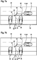
- FIGS. 7a and b the parking is shown in a transverse parking space with and without a rear boundary.
- the driver is signaled the achievement of the first direction of travel change point 40 by signaling a step below distance to an obstacle.
- the distance to the virtual obstacle 61 is slightly less than the distance of the vehicle 10 to the vehicle 36, which limits the parking space to the left side.
- the vehicle 10 is moved starting from the first direction change point along the trajectory 43.
- the second virtual obstacle 62 was generated by the driver assistance system. Since there are no other objects in the vicinity of the virtual obstacle 62, the driver without the second virtual obstacle 62 would have an indication of the fact that he had reached the virtual obstacle 62 second turnaround point missing. The achievement of this second turnaround point 42, however, is communicated to the driver by falling below a distance to the virtual obstacle 62, so that the vehicle 10 comes to a stop at the second turnaround point 42.
- the third and last parking train is executed backwards.
- the third virtual obstacle 63 was generated by the driver assistance system. This coincides with the wall 32 in the figure shown in FIG. 7a.
Landscapes
- Engineering & Computer Science (AREA)
- Transportation (AREA)
- Mechanical Engineering (AREA)
- Human Computer Interaction (AREA)
- Chemical & Material Sciences (AREA)
- Combustion & Propulsion (AREA)
- Radar, Positioning & Navigation (AREA)
- Remote Sensing (AREA)
- Control Of Driving Devices And Active Controlling Of Vehicle (AREA)
- Traffic Control Systems (AREA)
Description
- Die Erfindung betrifft ein Verfahren zur Unterstützung eines Fahrers eines Fahrzeugs, wobei das Fahrzeug ein Abstandswarnsystem, welches dem Fahrer einen Abstand zu einem Hindernis in der Umgebung des Fahrzeugs signalisiert, und ein Fahrassistenzsystem, welches bei einem Fahrmanöver die Querführung steuert, umfasst sowie eine Vorrichtung zur Durchführung des Verfahrens.
- Assistenzsysteme zur Unterstützung eines Fahrers eines Fahrzeugs bei einem Fahrmanöver werden immer häufiger in moderne Fahrzeuge eingebaut. Diese Fahrassistenzsysteme umfassen beispielsweise Abstandswarnsysteme, die Hindernisse in der Umgebung des Fahrzeugs ermitteln und den Fahrer bei Unterschreitung eines Mindestabstands warnen. Desweiteren werden diese Fahrassistenzsysteme auch zur Unterstützung des Fahrers beim Ein- und Ausparken eingesetzt. Je nach Ausführungsform des Assistenzsystems wird der Fahrer dabei nicht nur über Anweisungen, sondern auch durch Lenkeingriffe und/oder Bremseingriffe unterstützt, sodass sich die Tätigkeit des Fahrers nach Aktivierung des Assistenzsystems auf die Kontrolle des Fahrmanövers und auf das Beschleunigen und Bremsen beschränkt.
- Aus
DE 10 2004 011 088 A1 ist ein Verfahren zur Unterstützung eines Fahrers bei einem Einparkmanöver bekannt. Die Umgebung des Fahrzeugs wird mit Sensoren vermessen und bei Vorhandensein einer ausreichend großen Parklücke wird dem Fahrer ein unterstütztes Einparken angeboten. Das Assistenzsystem ermittelt die optimale Einparkstrategie und gibt über die optische Anzeigevorrichtung eines bereits im Fahrzeug vorhandenen Abstandswarnsystems Lenkanweisungen. Die optische Anzeige ist hier als Balkenanzeige ausgeführt, über die der Fahrer die Abweichung des Ist-Lenkwinkels vom angeforderten Soll-Lenkwinkel ablesen kann. Bei Bedarf kann auch eine akustische Ausgabe der Lenkanweisungen erfolgen. -
DE 10 2008 020 561 A1 beschreibt ein Verfahren und eine Vorrichtung bei der dem Fahrer sowohl eine noch zu fahrende Strecke, als auch ein Abstand zu einem Hindernis signalisiert werden kann. Die Vorrichtung umfasst Mittel zur Messung des Abstands zwischen einem Fahrzeug und einem Punkt und eine optische Anzeige in Form eines Fortschrittsbalkens zur Darstellung dieses Abstands. Der Punkt, zu dem der Abstand ermittelt wird, kann dabei beispielsweise ein Hindernis, eine Begrenzung eines Parkplatzes oder eine Stelle sein, an der ein Fahrtrichtungswechsel zum optimalen Einparken erfolgen sollte. Eine akustische Signalisierung der Abstandsinformation wird nicht beschrieben. - Aus
DE 10 2004 001 122 A1 ist ein Fahrassistenzsystem bekannt, welches einem Fahrer beim Einparken Anweisungen in Form von Tönen oder optischen Anzeigen signalisiert. Über verschiedene Tonsignale wird dem Fahrer der verbleibende Abstand zu einem Haltepunkt angezeigt. Ein besonderes Signal wird dem Fahrer, je nach seiner Reaktionsgeschwindigkeit, kurz vor Erreichen eines Stopppunktes gegeben, sodass das Fahrzeug am definierten Punkt zum Stillstand kommt. Auch die Soll-Lenkrichtung kann über akustische Signale angezeigt werden. -
EP 2 581 272 A1 offenbart ein Verfahren zur Unterstützung eines Fahrers eines Fahrzeugs, wobei das Fahrzeug ein Abstandswarnsystem, welches dem Fahrer einen Abstand zu einem Hindernis in der Umgebung des Fahrzeugs signalisiert, und ein Fahrassistenzsystem, welches bei einem Fahrmanöver die Querführung steuert, umfasst, wobei dem Fahrer Längsführungshinweise des Fahrassistenzsystems über eine Signalisierungsvorrichtung des Abstandswarnsystems angezeigt werden. - Bei den aus dem Stand der Technik bekannten Fahrassistenzsystemen ergeben sich Nachteile bei Fahrzeugen, die sowohl mit einem Abstandswarnsystem als auch mit einem Fahrassistenzsystem, welches bei einem Fahrmanöver die Querführung steuert, ausgestattet sind. Werden beispielsweise sowohl durch das Abstandswarnsystem optische und/oder akustische Abstandswarnungen als auch von dem Fahrassistenzsystem optische und/oder akustische Fahrhinweise zu Fahrtrichtungswechseln gegeben, erhält der Fahrer sehr viele unterschiedliche optische und/oder akustische Hinweise. Hierdurch kann es leicht zu einer Überlastung des Fahrers in komplexen Fahrsituationen wie beispielsweise beim Einparken kommen. Dabei ist eine exakte und schnelle Reaktion des Fahrers erforderlich, da das Parkendergebnis erheblich vom genauen Erreichen der Fahrtrichtungswechselpunkte abhängt.
- Werden nur durch das Abstandswarnsystem optische und/oder akustische Hinweise gegeben und angenommen, dass der Fahrer bei einem Einparkmanöver bei Annäherung an eine Parklückenbegrenzung durch die erfolgte Abstandswarnung zu einem Fahrtrichtungswechsel bzw. Gangwechsel animiert wird, wird zwar die Menge an Hinweisen reduziert, jedoch ergeben sich dabei weitere Nachteile. So erfolgt beispielsweise kein Hinweis auf einen Fahrtrichtungswechsel, wenn die Parklücke nur auf einer Seite begrenzt ist und das Fahrassistenzsystem kann keinen Hinweis geben, falls die optimale Zuglänge zum Erreichen einer guten Endparkposition bereits vor dem parklückenbegrenzenden Objekt endet.
- Es wird ein Verfahren zur Unterstützung eines Fahrers eines Fahrzeugs vorgeschlagen, wobei das Fahrzeug ein Abstandswarnsystem, welches dem Fahrer einen Abstand zu einem Hindernis in der Umgebung des Fahrzeugs signalisiert, und ein Fahrassistenzsystem, welches bei einem Fahrmanöver die Querführung steuert, umfasst, wobei dem Fahrer Längsführungshinweise des Fahrassistenzsystems über eine Signalisierungsvorrichtung des Abstandswarnsystems angezeigt werden.
- Das Abstandswarnsystem und das Fahrassistenzsystem können dabei in einem gemeinsamen System oder als eigenständige, aber miteinander verbundene, Systeme ausgeführt sein. Das gemeinsame System oder die beiden voneinander unabhängigen Systeme verfügen über Sensoren, mit denen Objekte in der Umgebung des Fahrzeugs erfasst werden und das Abstandswarnsystem umfasst eine Signalisierungsvorrichtung mit der ein Abstand zu einem Objekt in der Umgebung des Fahrzeugs angezeigt werden kann. Sind die beiden Systeme unabhängig voneinander ausgeführt, umfasst jedes System ein eigenes Steuergerät, wobei beide Steuergeräte mit der Signalisierungsvorrichtung des Abstandswarnsystems verbunden sind. Sind Abstandswarnsystem und Fahrassistenzsystem zusammen als gemeinsames System ausgeführt, umfasst das System ein einziges Steuergerät, welches beide Funktionalitäten implementiert. Das Fahrassistenzsystem ist eingerichtet, bei einem unterstützten Fahrmanöver die Querführung zu steuern, beispielsweise über eine Verbindung des Steuergeräts mit einer Servolenkung, das Beschleunigen und Bremsen des Fahrzeugs obliegt dem Fahrer des Fahrzeugs. Dazu gibt das Fahrassistenzsystem dem Fahrer Längsführungshinweise über die Signalisierungsvorrichtung des Abstandswarnsystems.
- In einer Ausführungsform des Verfahrens kann durch das Fahrassistenzsystem bei Überschreitung einer vorgegebenen Höchstgeschwindigkeit und/oder bei Unterschreitung eines Mindestabstands zu einem Objekt in der Umgebung des Fahrzeugs ein Bremseingriff erfolgen.
- In der Erfindung werden dem Fahrer die Längsführungshinweise in Form eines Abstands des Fahrzeugs zu einem Punkt, an dem ein Fahrrichtungswechsel erfolgen oder das Fahrzeug angehalten werden soll, angezeigt.
- In der Erfindung erzeugt das Fahrassistenzsystem zur Anzeige des Abstands zu dem Punkt, an dem ein Fahrtrichtungswechsel erfolgen oder das Fahrzeug angehalten werden soll, ein virtuelles Hindernis, welches vom Abstandswarnsystem wie ein tatsächliches Hindernis signalisiert wird.
- Dadurch wird erreicht, dass die zusätzliche Anzeige der Punkte, an dem ein Fahrtrichtungswechsel erfolgen oder das Fahrzeug angehalten werden soll, leicht in bestehende Abstandswarnsysteme integrierbar ist und die Signalisierung für den Fahrer auf gleiche Weise wie ein Abstand zu einem Hindernis erfolgt.
- Bei der Erzeugung eines virtuellen Hindernisses kann die Reaktionsgeschwindigkeit und die Fahrzeuggeschwindigkeit berücksichtigt werden, und der Abstand des virtuellen Hindernisses zum Fahrzeug mit einem Offset oder Faktor belegt werden. Dadurch wird erreicht, dass die Längsführungshinweise des Fahrassistenzsystems rechtzeitig gegeben werden und das Fahrzeug auch bei hoher Geschwindigkeit oder langsamer Reaktion des Fahrers am geplanten Punkt angehalten wird. Dieser aus Fahrzeuggeschwindigkeit und Reaktionsgeschwindigkeit des Fahrers gebildete Offset kann zusätzlich über Filter oder eine Hysteresefunktion beruhigt werden, damit Geschwindigkeitswechsel nicht zu einer sprunghaften Änderung der Abstandsanzeige führen.
- In einer weiteren Ausführungsform des Verfahrens wird zusätzlich die Richtung, in der ein Hindernis liegt, angezeigt. Dadurch ist es dem Fahrer beispielsweise beim Einparken möglich, abzuschätzen, ob der nächste Einparkzug in Vorwärts- oder Rückwärtsrichtung erfolgt.
- In einer Ausführungsform des Verfahrens erfolgt das Anzeigen der Längsführungshinweise akustisch, wobei der Abstand zu einem Hindernis über verschiedene Töne und/oder Tonfolgen angezeigt wird. Dabei ist es denkbar, den Abstand beispielsweise über die Tonhöhe anzuzeigen, wobei beispielsweise tiefere Töne einen größeren Abstand als hohe Töne signalisieren, und/oder über eine Tonfolge, bei der kurze Abstände zwischen den Tönen einen kurzen Abstand und lange Abstände zwischen den Tönen einen längeren Abstand anzeigen.
- In einer weiteren Ausführungsform des Verfahrens erfolgt das Anzeigen der Längsführungshinweise optisch, wobei der Abstand zu einem Hindernis über mehrere Leuchtanzeigen und/oder über eine Balkenanzeige dargestellt wird. Die Anzeige lässt sich beispielsweise über mehrere Leuchtdioden umsetzen, wobei der Abstand über die Anzahl und/oder die Farbe der angesteuerten Leuchtdioden angezeigt wird. Ist in dem Fahrzeug ein Bildschirm, beispielsweise für ein Navigationssystem, vorhanden, kann auch dieser genutzt werden um den Abstand über einen Fortschrittsbalken darzustellen.
- Je nach Möglichkeiten der Signalisierungsvorrichtung wird über eine Minimumbildung der kürzeste Abstand zu einem Hindernis signalisiert. Desweiteren ist es möglich beispielsweise bei einer optischen Anzeige die Umgebung des Fahrzeugs mit allen Hindernissen darzustellen. Durch die Behandlung der Punkte, an denen ein Fahrtrichtungswechsel erfolgen oder das Fahrzeug angehalten werden soll, als virtuelles Hindernis wird ein intuitives Erfassen der Situation durch den Fahrer ermöglicht.
- Ein weiterer Aspekt der Erfindung ist es eine Vorrichtung zur Unterstützung eines Fahrers eines Fahrzeugs bereitzustellen, wobei die Vorrichtung Sensoren zur Erfassung eines Abstands des Fahrzeugs zu einem Hindernis, eine Signalisierungsvorrichtung und mindestens ein Steuergerät umfasst, wobei entweder ein Steuergerät als Steuergerät für ein Abstandswarnsystem und ein Fahrassistenzsystem ausgeführt ist, oder jeweils ein Steuergerät als Steuergerät für ein Abstandswarnsystem und ein Steuergerät als Steuergerät für ein Fahrassistenzsystem ausgeführt ist und das mindestens eine Steuergerät zur Durchführung des erfindungsgemäßen Verfahrens eingerichtet ist.
- Die Sensoren zur Erfassung eines Abstands können dabei beispielsweise als Ultraschallsensoren, Radarsensoren, Lidarsensoren oder als optische Kameras ausgeführt sein. Zur Steuerung der Querführung und gegebenenfalls zur Vornahme eines Bremseingriffs ist die Vorrichtung mit weiteren Steuergeräten im Fahrzeug wie beispielsweise der Servolenkung oder des Antiblockiersystems (ABS) verbunden.
- In einer Ausführungsform der Vorrichtung umfasst die Signalisierungseinrichtung einen Lautsprecher, eine optische Abstandsanzeigeeinrichtung, einen grafischen Bildschirm oder eine Kombination mindestens zwei dieser Mittel.
- Erfindungsgemäß wird weiterhin ein Computerprogramm vorgeschlagen, gemäß dem eines der hierin beschriebenen Verfahren durchgeführt wird, wenn das Computerprogramm auf einer programmierbaren Computereinrichtung ausgeführt wird. Bei dem Computerprogramm kann es sich beispielsweise um ein Modul zur Implementierung eines Fahrassistenzsystems oder eines Subsystems hiervon in einem Fahrzeug handeln oder um eine Applikation für Fahrassistenzfunktionen, welche auf einem Smartphone ausführbar ist. Das Computerprogramm kann auf einem maschinenlesbaren Speichermedium gespeichert werden, etwa auf einem permanenten oder wiederbeschreibbaren Speichermedium oder in Zuordnung zu einer Computereinrichtung oder auf einer entfernbaren CD-Rom, DVD oder einem USB-Stick. Zusätzlich oder alternativ kann das Computerprogramm auf einer Computereinrichtung wie etwa auf einem Server zum Herunterladen bereitgestellt werden, zum Beispiel über ein Datennetzwerk wie das Internet oder eine Kommunikationsverbindung wie etwa eine Telefonleitung oder eine drahtlose Verbindung.
- Des Weiteren betrifft die Erfindung ein Fahrzeug, welches mit der erfindungsgemäßen Vorrichtung zur Unterstützung eines Fahrers eines Fahrzeugs ausgerüstet ist.
- Durch das erfindungsgemäße Verfahren kann ein Fahrassistenzsystem, welches einen Fahrer bei einem Fahrmanöver unterstützt und die Querführung steuert, die gleiche Signalisierungsvorrichtung wie ein ebenfalls im Fahrzeug vorhandenes Abstandswarnsystem verwenden. Dadurch wird zum einen das Integrieren zusätzlicher Anzeigevorrichtungen überflüssig, wodurch die Integration des Fahrassistenzsystems in das Fahrzeug vereinfacht wird. Zum Anderen erhält der Fahrer sämtliche bei einem Einparkmanöver relevanten Informationen, nämlich den Abstand zu einem Hindernis und den Abstand zu einem Punkt an dem ein Fahrtrichtungswechsel erfolgen oder das Fahrzeug angehalten werden soll, über eine einzige Signalisierungsvorrichtung. Dabei kann der Fahrer bei einem Einparkmanöver intuitiv auf die entsprechenden Hinweise des Fahrassistenzsystems reagieren, ohne dass dieser durch sehr viele unterschiedliche Hinweise abgelenkt oder überfordert wird. Das Fahrassistenzsystem kann den Fahrer bei einem Fahrmanöver gezielt zu einem Fahrtrichtungswechselpunkt führen, den Fahrer bei überhöhter Geschwindigkeit bremsen und/oder den Fahrer bei Abweichungen von der idealen Bahn warnen.
- Da die Punkte, an denen ein Fahrtrichtungswechsel erfolgen oder das Fahrzeug angehalten werden soll, als virtuelle Hindernisse behandelt werden, ist deren Signalisierungsart dem Fahrer schon bekannt, sodass er sich auch an keine neuen Systeme gewöhnen muss.
- Das erfindungsgemäße Verfahren lässt sich in allen Fahrmanövern einsetzen, bei denen ein Fahrassistenzsystem die Querführung steuert, beispielsweise beim Ein- oder Ausparken aus Längs-, Quer- und Schrägparklücken.
- Anhand der Figuren wird die Erfindung nachstehend eingehender beschrieben.
- Es zeigen:
-
Figur 1 eine Ausführungsform der Vorrichtung mit einem gemeinsamen Steuergerät für ein Abstandswarnsystem und ein Fahrassistenzsystem, -
Figur 2 eine Ausführungsform der Vorrichtung mit jeweils einem Steuergerät für ein Abstandswarnsystem und ein Fahrassistenzsystem, -
Figuren 3a und b das Einparken in eine Längsparklücke mit und ohne laterale Begrenzung, -
Figur 4a das Einparken in eine nur an einer Seite begrenzte Längsparklücke, -
Figur 4b das Einparken eines Fahrzeugs in eine große Längsparklücke, -
Figur 5 das Einparken in eine Längsparklücke bei Abweichung von der idealen Trajektorie, -
Figur 6 das Einparken in eine Schrägparklücke, -
Figuren 7a und b das Einparken in eine Querparklücke mit und ohne Begrenzung. - In
Figur 1 ist ein Fahrzeug mit einer ersten Ausführungsform der Vorrichtung dargestellt. -
Figur 1 zeigt ein Fahrzeug 10 in dem in der Front Abstandssensoren 12 und im Heck Abstandssensoren 14 angeordnet sind. Die Abstandssensoren 12, 14 sind mit einem Steuergerät 20 verbunden, welches sowohl die Funktion eines Abstandswarnsystems als auch die Funktion eines Fahrassistenzsystems, welches bei einem Fahrmanöver die Querführung steuert, implementiert. Das Steuergerät 20 ist mit einer Signalisierungsvorrichtung 26 gekoppelt. In dieser ersten Ausführungsform der Vorrichtung werden die Abstandssensoren 12, 14 sowohl für eine Abstandswarnung, die den Fahrer bei Unterschreitung eines Mindestabstands zu einem Objekt in der Umgebung des Fahrzeugs 10 warnt, als auch für ein weiteres Fahrassistenzsystem genutzt. Dieses weitere Fahrassistenzsystem übernimmt bei einem Fahrmanöver die Querführung, das heißt die Lenkung des Fahrzeugs 10. Das Beschleunigen und das Abbremsen des Fahrzeugs obliegt dabei dem Fahrer, wobei er bei einem geführten Fahrmanöver Längsführungsanweisungen erhält. Diese Längsführungshinweise werden von dem im Steuergerät 20 implementierten Fahrassistenzsystem generiert. Zur Signalisierung werden aus diesen Längsführungshinweisen virtuelle Hindernisse erzeugt, wobei diese virtuellen Hindernisse anschließend vom Steuergerät 20 genauso wie real über die Abstandssensoren 12, 14 detektierte Hindernisse behandelt werden. - Bei der Erzeugung eines virtuellen Hindernisses kann die Fahrzeuggeschwindigkeit und/oder die Reaktionsgeschwindigkeit des Fahrers über einen Offset oder Faktor berücksichtigt werden. Dabei wird beispielsweise auf die Entfernung des virtuellen Hindernisses zum Fahrer ein Offset subtrahiert, der dem Weg entspricht, den das Fahrzeug bei der aktuellen Geschwindigkeit innerhalb der Reaktionszeit des Fahrers zurücklegen würde. Ebenfalls möglich ist es einen Korrekturfaktor zu verwenden, sodass beispielsweise die Entfernung zu den virtuellen Hindernissen immer 10% geringer ausfällt. Auf diese Weise erfolgt eine Signalisierung des virtuellen Hindernisses immer so frühzeitig, dass unter Berücksichtigung der Fahrzeuggeschwindigkeit und/oder der Reaktionsgeschwindigkeit des Fahrers das Fahrzeug genau zu dem vom Fahrassistenzsystem bestimmten Punkt geführt wird.
- In
Figur 2 ist eine weitere Ausführungsform der erfindungsgemäßen Vorrichtung dargestellt. -
Figur 2 zeigt ein Fahrzeug 10 mit einer Gruppe von Abstandssensoren 12 in der Front des Fahrzeugs und einer Gruppe von Abstandssensoren 14 im Heck des Fahrzeugs. Die Abstandssensoren 12, 14 sind mit einem Steuergerät 22 verbunden, welches die Funktion eines Abstandwarnsystems implementiert. Das Steuergerät 22 ist mit einer Signalisierungsvorrichtung 26 gekoppelt, über die dem Fahrer der Abstand zu einem Objekt in der Umgebung des Fahrzeugs 10 signalisiert wird. - Das Fahrzeug 10 weist des Weiteren seitliche Abstandssensoren 16 im Frontbereich auf, die mit einem Steuergerät 24 gekoppelt sind. Das Steuergerät 24 implementiert ein Fahrassistenzsystem, welches bei einem Fahrmanöver die Querführung steuert, beispielsweise einen Einparkassistenten. Dieses Fahrassistenzsystem vermisst über die seitlichen Abstandssensoren 16 vorhandene Parklücken bei einer Vorbeifahrt des Fahrzeugs 10. Bei einem durch das Fahrassistenzsystem geführten Fahrmanöver wird die Querführung direkt durch das Steuergerät 24 gesteuert, die Längsführung, das heißt das Beschleunigen und/oder Abbremsen des Fahrzeugs, obliegt weiterhin dem Fahrer. Dazu erhält der Fahrer Längsführungshinweise, die durch das Steuergerät 24 erzeugt werden. Zur Signalisierung dieser Längsführungshinweise erzeugt das Steuergerät 24, wie bei der vorherigen Ausführungsform beschrieben, virtuelle Hindernisse. Diese virtuellen Hindernisse werden wie reale Hindernisse durch die Signalisierungsvorrichtung 26 dem Fahrer des Fahrzeugs 10 angezeigt. Je nach Ausführungsform ist die Signalisierungsvorrichtung 26 ebenfalls mit dem Steuergerät 24 des Fahrassistenzsystems verbunden oder es besteht eine indirekte Verbindung über das Steuergerät 22 des Abstandswarnsystems.
- In den
Figuren 3a ist das Einparken eines Fahrzeugs in eine Längsparklücke dargestellt. -
Figur 3a zeigt ein Fahrzeug 10, welches in eine Längsparklücke 34 eingeparkt werden soll. Die Längsparklücke 34 ist hinten durch das Fahrzeug 36, vorne durch das Fahrzeug 38 und zu einer Seite durch eine Mauer 32 begrenzt. Die Position des Fahrzeugs 10 wird im Folgenden auf einen Referenzpunkt 11 im Heck des Fahrzeugs bezogen beschrieben. Zu Beginn befindet sich das Fahrzeug 10 links neben dem Fahrzeug 38, welches die Längsparklücke 34 nach vorne begrenzt. Die Parklücke 34 wurde bei einer zuvor erfolgten Vorbeifahrt des Fahrzeugs 10 vermessen und dem Fahrer als Parklücke angeboten. Nach Aktivierung des geführten Einparkmanövers durch den Fahrer steuert das - Fahrassistenzsystem die Querführung, das heißt die Lenkung des Fahrzeugs 10. Die Längsführung, das heißt das Beschleunigen und/oder Abbremsen des Fahrzeugs 10, obliegt weiterhin dem Fahrer.
- Der erste Einparkzug wird vom Fahrer des Fahrzeugs 10 in Richtung der Parklücke 34, das heißt rückwärts, ausgeführt. Das Fahrzeug 10 fährt dabei von der Startposition 11 entlang der Trajektorie 41 zum ersten Fahrtrichtungswechselpunkt 40. Zur Signalisierung der noch zu fahrenden Strecke wird durch das Fahrassistenzsystem ein erstes virtuelles Hindernis 61 erzeugt. In der in
Figur 3 a dargestellten Situation liegt das erste virtuelle Hindernis im Bereich der Mauer 32, die die Parklücke 34 begrenzt. Dem Fahrer wird durch die Signalisierungsvorrichtung jeweils der Abstand zum nächstgelegenen Hindernis signalisiert, wobei in der inFigur 3a dargestellten Situation der Abstand zur Mauer 32 und zum ersten virtuellen Hindernis 61 ungefähr gleich sind. Der Fahrer des Fahrzeugs 10 fährt entlang der Trajektorie 41 rückwärts, bis ihm durch die Signalisierungsvorrichtung das Unterschreiten eines Mindestabstands zu einem Hindernis mitgeteilt wird. Daraufhin bremst der Fahrer und das Fahrzeug 10 kommt am ersten Fahrtrichtungswechselpunkt 40 zum stehen. Bei einem zweiten Einparkzug wechselt der Fahrer des Fahrzeugs 10 in den Vorwärtsgang und fährt entlang der zweiten Trajektorie 43 in Richtung des zweiten Fahrtrichtungswechselpunkts 42. Als Längsführungshinweis wurde durch das Fahrassistenzsystem das zweite virtuelle Hindernis 62 erzeugt. Das zweite virtuelle Hindernis 62 liegt ungefähr auf Höhe des Hecks des Fahrzeugs 38, welches die Parklücke 34 nach vorne begrenzt. Wiederum wird dem Fahrer der Abstand zum nächstgelegenen Hindernis signalisiert, sodass der Fahrer das Fahrzeug 10 am zweiten Fahrtrichtungswechselpunkt 42 stoppt. - Für den dritten und letzten Einparkzug legt der Fahrer des Fahrzeugs 10 wieder den Rückwärtsgang ein und bewegt das Fahrzeug 10 entlang der dritten Einparktrajektorie 45. Als Längsführungshinweis wurde vom Fahrassistenzsystem das dritte virtuelle Hindernis 63 erzeugt, welches in der in
Figur 3a dargestellten Situation mit der Front des Fahrzeugs 36, welches die Parklücke 34 nach hinten begrenzt, zusammenfällt. Nach der Signalisierung der Unterschreitung eines Mindestabstands zum nächstgelegenen Hindernis wird das Fahrzeug 10 durch den Fahrer an der Endposition 44 gestoppt. - In
Figur 3b wird das Einparken in eine Längsparklücke dargestellt, wobei die Längsparklücke seitlich nicht begrenzt ist. - In
Figur 3b ist wieder Fahrzeug 10 dargestellt, welches in eine Längsparklücke einfahren soll, die nach hinten durch das Fahrzeug 36 und nach vorne durch das Fahrzeug 38 begrenzt ist. Eine seitliche Begrenzung der Längsparklücke 34 fehlt. Die Parklücke 34 wurde wieder bei einer Vorbeifahrt des Fahrzeugs 10 vermessen und wird vom Fahrassistenzsystem dem Fahrer angeboten. Nach Aktivierung des geführten Fahrmanövers wird die Querführung durch das Fahrassistenzsystem gesteuert und das erste virtuelle Hindernis 61 erzeugt. Der Fahrer fährt das Fahrzeug 10 ausgehend von der Startposition 46 entlang der ersten Einparktrajektorie 41, bis ihm durch die Signalisierungsvorrichtung die Unterschreitung eines Mindestabstands zum virtuellen Hindernis 61 signalisiert wird. Daraufhin stoppt der Fahrer das Fahrzeug 10 am ersten Fahrtrichtungswechselpunkt 40. Ohne das erste virtuelle Hindernis 61 würde der Fahrer keinen Hinweis auf die Lage des ersten Fahrtrichtungswechselpunkts 40 erhalten. - Der zweite Einparkzug wird in Vorwärtsrichtung ausgeführt. Als Längsführungshinweis wurde vom Fahrassistenzsystem das virtuelle Hindernis 62 erzeugt, welches wieder mit der vorderen Begrenzung der Parklücke 34 zusammenfällt. Die Unterschreitung eines Mindestabstands zum virtuellen Hindernis 62 beziehungsweise zum vorderen Fahrzeug 38 wird dem Fahrer wieder signalisiert, sodass das Fahrzeug 10 vom Fahrer am zweiten Fahrtrichtungswechselpunkt 42 gestoppt wird.
- Der dritte und letzte Einparkzug wird wieder in Rückwärtsgang ausgeführt. Das Fahrzeug bewegt sich dabei entlang der dritten Einparktrajektorie 45. Als Längsführungshinweis wurde vom Fahrassistenzsystem das virtuelle Hindernis 63 erzeugt, welches in der in
Figur 3b dargestellten Situation mit der hinteren Begrenzung 36 der Längsparklücke 34 zusammenfällt. - Wiederum stoppt der Fahrer des Fahrzeugs 10 die Rückwärtsfahrt bei der Signalisierung einer Abstandsunterschreitung. Das Fahrzeug hat dann die Endposition 44 erreicht.
-
Figur 4a zeigt das Einparken in eine nur nach vorne und zur Seite begrenzte Längsparklücke. - In der in
Figur 4a dargestellten Situation wird eine Längsparklücke 34 zur Seite durch eine Mauer 32 und nach vorne durch ein Fahrzeug 38 begrenzt. Bei einer Vorbeifahrt des Fahrzeugs 10 an der Parklücke 34 wurde diese vermessen und wird vom Fahrassistenzsystem dem Fahrer des Fahrzeugs 10 angeboten. Nach Aktivierung des geführten Fahrmanövers durch den Fahrer wird die Querführung des Fahrzeugs 10 durch das Fahrassistenzsystem gesteuert. Als Längsführungshinweis wird das virtuelle Hindernis 61 erzeugt. Der Fahrer beginnt das Einparkmanöver im Rückwärtsgang und fährt entlang der Trajektorie 41. Da der Parklücke 34 eine hintere Begrenzung fehlt, würde der Fahrer ohne das virtuelle Hindernis 61 nie eine Abstandswarnung erhalten, die ihn zum Stoppen des Fahrzeugs 10 an der optimalen Endposition 44 veranlassen würde. - In
Figur 4b ist das Einparken in eine Längsparklücke dargestellt. - In der in 4b dargestellten Fahrsituation soll das Fahrzeug 10 in die Längsparklücke 34 eingeparkt werden, die nach vorne durch das Fahrzeug 38, nach hinten durch das Fahrzeug 36 und zur Seite durch die Mauer 32 begrenzt ist. Dabei hat der Fahrer bereits den ersten Einparkzug ausgehend von der Startposition 46 zum ersten Fahrtrichtungswechselpunkt 40 und den zweiten Einparkzug vom ersten Fahrtrichtungswechselpunkt 40 zum zweiten Fahrtrichtungswechselpunkt 42 ausgeführt. Das Ende des zweiten Einparkzuges wurde dem Fahrer des Fahrzeugs 10 durch das virtuelle Hindernis 62 signalisiert, welches aufgrund der Größe der Längsparklücke 34 nicht mit der vorderen Begrenzung 38 zusammenfällt. Ohne das zweite virtuelle Hindernis 62 hätte der Fahrer des Fahrzeugs 10 das Fahrzeug erst kurz vor Erreichen der vorderen Begrenzung 38 gestoppt und wäre somit von der optimalen Einparktrajektorie abgewichen.
- In
Figur 5 ist das Einparken in eine Längsparklücke dargestellt. -
Figur 5 zeigt ein Fahrzeug 10, welches in eine Längsparklücke 34, die nach vorne durch das Fahrzeug 38 und nach hinten durch das Fahrzeug 36 begrenzt ist, eingeparkt werden soll. Zur Seite ist die Parklücke durch eine Bordsteinkante 31 begrenzt, die jedoch aufgrund ihrer geringen Höhe durch das Abstandswarnsystem nicht erfasst werden kann. In der inFigur 5 dargestellten Situation ist der Fahrer des Fahrzeugs 10 zu schnell gefahren, sodass die tatsächlich gefahrene Einparktrajektorie 41 von der idealen vorberechneten Trajektorie 50 abweicht. Es droht eine Kollision mit der Bordsteinkante 31, die vom Abstandswarnsystem nicht erfasst wird. Jedoch wird dem Fahrer des Fahrzeugs 10 hier die Unterschreitung des Abstands zum virtuellen Hindernis 61 signalisiert, sodass dieser das Fahrzeug 10 stoppt. -
Figur 6 zeigt das Einparken in eine Querparklücke. - In der in
Figur 6 dargestellten Situation soll das Fahrzeug 10 in eine Querparklücke 33 eingeparkt werden. Die Querparklücke 33 wird durch die geparkten Fahrzeuge 36 und 38 an den Seiten begrenzt. Eine hintere Begrenzung der Parklücke 33 fehlt. Die Querparklücke 33 wurde bei einer Vorbeifahrt des Fahrzeugs 10 vermessen und wird dem Fahrer des Fahrzeugs angeboten. Nach Aktivierung des geführten Fahrmanövers übernimmt das Fahrassistenzsystem die Querführung und generiert als Längsführungshinweis das virtuelle Hindernis 61. Ausgehend von der Startposition 46 fährt das Fahrzeug 10 im Rückwärtsgang so lange, bis eine Unterschreitung eines Abstands zum virtuellen Hindernis 61 signalisiert wird. Daraufhin stoppt der Fahrer das Fahrzeug 10 in der Endposition 44. - In den
Figuren 7a und b wird das Einparken in eine Querparklücke mit und ohne hintere Begrenzung dargestellt. - In
Figur 7a soll das Fahrzeug 10 in eine Querparklücke 35 eingeparkt werden. Die Querparklücke 35 wird zur linken Seite durch das Fahrzeug 36, zur rechten Seite durch das Fahrzeug 38 und nach hinten durch eine Mauer 32 begrenzt. Die Parklücke 35 wurde bei einer Vorbeifahrt des Fahrzeugs 10 vermessen und wird dem Fahrer angeboten. Nach Aktivierung des geführten Fahrmanövers übernimmt das Fahrassistenzsystem die Querführung. Um dem Fahrer einen Längsführungshinweis zu geben, wird vom Fahrassistenzsystem das erste virtuelle Hindernis 61 generiert, welches ungefähr mit der linken Begrenzung 36 zusammenfällt. - Beim ersten Einparkzug von der Startposition 46 entlang der ersten Einparktrajektorie 41 wird dem Fahrer das Erreichen des ersten Fahrtrichtungswechselpunkts 40 durch eine Signalisierung eines unterschrittenen Abstands zu einem Hindernis signalisiert. In der dargestellten Situation ist dabei der Abstand zum virtuellen Hindernis 61 ein wenig geringer als der Abstand des Fahrzeugs 10 zum Fahrzeug 36, welches die Parklücke zur linken Seite hin begrenzt.
- Im darauf folgenden vorwärts ausgeführten zweiten Einparkzug wird das Fahrzeug 10 ausgehend vom ersten Fahrtrichtungswechselpunkt entlang der Trajektorie 43 bewegt. Als Längsführungshinweis wurde vom Fahrassistenzsystem das zweite virtuelle Hindernis 62 generiert. Da in der Nähe des virtuellen Hindernisses 62 keine weiteren Objekte sind, würde dem Fahrer ohne das zweite virtuelle Hindernis 62 ein Hinweis auf das Erreichen des zweiten Fahrtrichtungswechselpunkts fehlen. Das Erreichen dieses zweiten Fahrtrichtungswechselpunkts 42 wird dem Fahrer jedoch durch eine Unterschreitung eines Abstands zum virtuellen Hindernis 62 mitgeteilt, sodass das Fahrzeug 10 am zweiten Fahrtrichtungswechselpunkt 42 zum Stehen kommt.
- Ausgehend vom zweiten Fahrtrichtungswechselpunkt 42 wird der dritte und letzte Einparkzug rückwärts ausgeführt. Als Längsführungshinweis wurde vom Fahrassistenzsystem das dritte virtuelle Hindernis 63 erzeugt. Dieses fällt in der Figur in 7a dargestellten Situation mit der Mauer 32 zusammen.
- In
Figur 7b fehlt die Mauer 32, sodass ohne das dritte virtuelle Hindernis 63 dem Fahrer das Erreichen der Endposition 44 nicht signalisiert werden würde. - Bei Unterschreitung eines Mindestabstands zum virtuellen Hindernis 63 wird dies dem Fahrer signalisiert, sodass dieser sowohl in der in
Figur 7a als auch in der inFigur 7b dargestellten Situation die Endposition 44 erreicht.
Claims (8)
- Verfahren zur Unterstützung eines Fahrers eines Fahrzeugs (10), wobei das Fahrzeug (10) ein Abstandswarnsystem, welches dem Fahrer einen Abstand zu einem Hindernis in der Umgebung des Fahrzeugs (10) signalisiert, und ein Fahrassistenzsystem, welches bei einem Fahrmanöver die Querführung steuert, umfasst, dadurch gekennzeichnet, dass dem Fahrer Längsführungshinweise des Fahrassistenzsystems über eine Signalisierungsvorrichtung (26) des Abstandswarnsystems angezeigt werden, wobei die Längsführungshinweise in Form eines Abstands des Fahrzeugs (10) zu einem Punkt (40, 42, 44), an dem ein Fahrtrichtungswechsel erfolgen oder das Fahrzeug (10) angehalten werden soll, angezeigt werden und wobei das Fahrassistenzsystem zur Anzeige des Abstands zu dem Punkt (40, 42, 44), an dem ein Fahrtrichtungswechsel erfolgen oder das Fahrzeug (10) angehalten werden soll, ein virtuelles Hindernis (61, 62, 63) erzeugt, welches vom Abstandswarnsystem wie ein tatsächliches Hindernis signalisiert wird.
- Verfahren nach Anspruch 1, dadurch gekennzeichnet, dass die Richtung, in der ein Hindernis liegt, angezeigt wird.
- Verfahren nach Anspruch 1 oder 2, dadurch gekennzeichnet, dass das Anzeigen der Längsführungshinweise akustisch erfolgt, wobei der Abstand zu einem Hindernis über verschiedene Töne und/oder Tonfolgen angezeigt wird.
- Verfahren nach einem der Ansprüche 1 bis 3, dadurch gekennzeichnet, dass das Anzeigen der Längsführungshinweise optisch erfolgt, wobei der Abstand zu einem Hindernis über mehrere Leuchtanzeigen und/oder über eine Balkenanzeige dargestellt wird.
- Vorrichtung zur Unterstützung eines Fahrers eines Fahrzeugs (10), wobei die Vorrichtung Sensoren (12, 14, 16) zur Erfassung eines Abstands des Fahrzeugs (10) zu einem Hindernis, eine Signalisierungsvorrichtung (26) und mindestens ein Steuergerät (20, 22, 24) umfasst, wobei entweder ein Steuergerät als Steuergerät für ein Abstandswarnsystem und ein Fahrassistenzsystem (20) ausgeführt ist oder jeweils ein Steuergerät als Steuergerät für ein Abstandswarnsystem (22) und ein Steuergerät als Steuergerät für ein Fahrassistenzsystem (24) ausgeführt ist und das mindestens eine Steuergerät (20, 22, 24) zur Durchführung des Verfahrens nach einem der Ansprüche 1 bis 4 eingerichtet ist.
- Vorrichtung nach Anspruch 5, dadurch gekennzeichnet, dass die Signalisierungseinrichtung (26) einen Lautsprecher, eine optische Abstandsanzeigeeinrichtung, einen graphischen Bildschirm oder eine Kombination mindestens zwei dieser Mittel umfasst.
- Computerprogramm, das das Verfahren nach einem der Ansprüche 1 bis 4 ausführt, wenn es auf einem Computer abläuft.
- Fahrzeug mit einer Vorrichtung nach Anspruch 5 oder 6.
Applications Claiming Priority (2)
| Application Number | Priority Date | Filing Date | Title |
|---|---|---|---|
| DE201210213899 DE102012213899A1 (de) | 2012-08-06 | 2012-08-06 | Verfahren zur Unterstützung eines Fahrers eines Fahrzeugs |
| PCT/EP2013/065391 WO2014023562A1 (de) | 2012-08-06 | 2013-07-22 | Verfahren zur unterstützung eines fahrers eines fahrzeugs |
Publications (2)
| Publication Number | Publication Date |
|---|---|
| EP2879939A1 EP2879939A1 (de) | 2015-06-10 |
| EP2879939B1 true EP2879939B1 (de) | 2016-12-28 |
Family
ID=48877222
Family Applications (1)
| Application Number | Title | Priority Date | Filing Date |
|---|---|---|---|
| EP13742192.1A Not-in-force EP2879939B1 (de) | 2012-08-06 | 2013-07-22 | Verfahren zur unterstützung eines fahrers eines fahrzeugs |
Country Status (3)
| Country | Link |
|---|---|
| EP (1) | EP2879939B1 (de) |
| DE (1) | DE102012213899A1 (de) |
| WO (1) | WO2014023562A1 (de) |
Families Citing this family (3)
| Publication number | Priority date | Publication date | Assignee | Title |
|---|---|---|---|---|
| DE102014111122A1 (de) | 2014-08-05 | 2016-02-11 | Valeo Schalter Und Sensoren Gmbh | Verfahren zum zumindest semi-autonomen Manövrieren eines Kraftfahrzeugs, Fahrerassistenzsystem sowie Kraftfahrzeug |
| DE102016208634B4 (de) * | 2016-05-19 | 2024-02-01 | Volkswagen Aktiengesellschaft | Verfahren zum Ausgeben einer Warninformation in einem Fahrzeug |
| CN111746525B (zh) * | 2020-07-07 | 2022-06-21 | 东风柳州汽车有限公司 | 泊车路径规划方法、装置、设备及存储介质 |
Family Cites Families (5)
| Publication number | Priority date | Publication date | Assignee | Title |
|---|---|---|---|---|
| DE102004001122A1 (de) | 2004-01-07 | 2005-08-04 | Robert Bosch Gmbh | Vorrichtung und Verfahren zum Bereitstellen von Informationen zum Parallel-Einparken eines Fahrzeuges |
| DE102004011088A1 (de) | 2004-02-06 | 2005-08-25 | Daimlerchrysler Ag | Verfahren zur Unterstützung des Fahrers bei einem Einparkmanöver |
| DE102008036009B4 (de) * | 2008-03-28 | 2018-03-22 | Volkswagen Ag | Verfahren zum Kollisionsschutz eines Kraftfahrzeugs und Parkhausassistent |
| DE102008020561A1 (de) | 2008-04-24 | 2009-10-29 | Volkswagen Ag | Verfahren und Vorrichtung zur Führung eines Fahrzeugs |
| JP5447663B2 (ja) * | 2010-06-11 | 2014-03-19 | 日産自動車株式会社 | 駐車支援装置及び方法 |
-
2012
- 2012-08-06 DE DE201210213899 patent/DE102012213899A1/de not_active Withdrawn
-
2013
- 2013-07-22 WO PCT/EP2013/065391 patent/WO2014023562A1/de not_active Ceased
- 2013-07-22 EP EP13742192.1A patent/EP2879939B1/de not_active Not-in-force
Non-Patent Citations (1)
| Title |
|---|
| None * |
Also Published As
| Publication number | Publication date |
|---|---|
| EP2879939A1 (de) | 2015-06-10 |
| DE102012213899A1 (de) | 2014-02-06 |
| WO2014023562A1 (de) | 2014-02-13 |
Similar Documents
| Publication | Publication Date | Title |
|---|---|---|
| EP2620351B1 (de) | Verfahren zur Unterstützung eines Fahrers beim Vorwärtseinparken | |
| EP1758755B1 (de) | Verfahren und vorrichtung zur fahrerunterstützung | |
| EP2569207B1 (de) | Verfahren zum einparken oder ausparken eines fahrzeugs sowie entsprechendes assistenzsystem und fahrzeug | |
| DE102009010006B4 (de) | Verfahren und Vorrichtung zum teilautonomen oder autonomen Fahren eines Kraftfahrzeugs | |
| EP2203329B1 (de) | Steuereinrichtung für eine anzeigeeinrichtung einer einparkeinrichtung und verfahren zur darstellung | |
| DE102005050576B4 (de) | Einparkhilfesystem und Einparkhilfeverfahren | |
| EP2032418B1 (de) | Steuergerät und verfahren zur fahrerunterstützung | |
| DE102012214208B4 (de) | Verfahren zum Betreiben eines Kraftfahrzeugs während einer vollautomatischen Fahrzeugführung | |
| DE102012214206B4 (de) | Verfahren zur Krümmungserkennung eines Fahrspurverlaufs während einer vollautomatischen Fahrzeugführung | |
| DE102009039084A1 (de) | Verfahren zum Unterstützen eines Fahrers eines Kraftfahrzeugs beim Einparken in eine Querparklücke, Fahrassistenzeinrichtung und Kraftfahrzeug mit einer Fahrerassistenzeinrichtung | |
| DE102006043149A1 (de) | Integrierter Quer- und Längsführungsassistent zur Unterstützung des Fahrers beim Fahrspurwechsel | |
| DE102013216630A1 (de) | Verfahren und Vorrichtung zur Steuerung eines assistierten Parkvorgangs eines Kraftfahrzeugs | |
| EP2170679A1 (de) | Parklenkassistenzsystem und verfahren zum unterstützen eines ausparkvorgangs | |
| DE102014012781B4 (de) | Spurwechselassistent, zugehöriges Betriebsverfahren und Kraftfahrzeug | |
| DE102010000964A1 (de) | Verfahren zur Unterstützung eines Fahrers eines Kraftfahrzeuges | |
| DE102006059915A1 (de) | Verfahren zum Bestimmen einer an eine Verkehrssituation angepassten Fahrzeugführung und Fahrerassistenzsystem | |
| EP3177505B1 (de) | Bereitstellen von fahrhinweisen während eines parkmanövers | |
| EP2493746B1 (de) | Verfahren zur unterstützung eines fahrers beim einparken | |
| EP2879939B1 (de) | Verfahren zur unterstützung eines fahrers eines fahrzeugs | |
| DE10335738A1 (de) | Verfahren und Vorrichtung zur Unterstützung des Fahrers eines Fahrzeugs bei der Druchführung eines Notbremsvorgangs | |
| EP1553009B1 (de) | Parkassistent zum Parallel-Einparken | |
| DE102005022663A1 (de) | Verfahren und Vorrichtung zur Fahrerunterstützung | |
| EP1642769B1 (de) | Verfahren zur Ausgabe von Einparkhinweisen | |
| DE102016004852A1 (de) | Verfahren zum Betrieb eines Fahrzeugs | |
| DE102008012910A1 (de) | Verfahren und Fahrassistenzvorrichtung zur Unterstützung eines Fahrers eines Fahrzeugs beim Einparken in eine Parklücke |
Legal Events
| Date | Code | Title | Description |
|---|---|---|---|
| PUAI | Public reference made under article 153(3) epc to a published international application that has entered the european phase |
Free format text: ORIGINAL CODE: 0009012 |
|
| 17P | Request for examination filed |
Effective date: 20150306 |
|
| AK | Designated contracting states |
Kind code of ref document: A1 Designated state(s): AL AT BE BG CH CY CZ DE DK EE ES FI FR GB GR HR HU IE IS IT LI LT LU LV MC MK MT NL NO PL PT RO RS SE SI SK SM TR |
|
| AX | Request for extension of the european patent |
Extension state: BA ME |
|
| DAX | Request for extension of the european patent (deleted) | ||
| GRAP | Despatch of communication of intention to grant a patent |
Free format text: ORIGINAL CODE: EPIDOSNIGR1 |
|
| INTG | Intention to grant announced |
Effective date: 20160913 |
|
| GRAS | Grant fee paid |
Free format text: ORIGINAL CODE: EPIDOSNIGR3 |
|
| GRAA | (expected) grant |
Free format text: ORIGINAL CODE: 0009210 |
|
| AK | Designated contracting states |
Kind code of ref document: B1 Designated state(s): AL AT BE BG CH CY CZ DE DK EE ES FI FR GB GR HR HU IE IS IT LI LT LU LV MC MK MT NL NO PL PT RO RS SE SI SK SM TR |
|
| REG | Reference to a national code |
Ref country code: GB Ref legal event code: FG4D Free format text: NOT ENGLISH |
|
| REG | Reference to a national code |
Ref country code: CH Ref legal event code: EP |
|
| REG | Reference to a national code |
Ref country code: AT Ref legal event code: REF Ref document number: 856999 Country of ref document: AT Kind code of ref document: T Effective date: 20170115 |
|
| REG | Reference to a national code |
Ref country code: IE Ref legal event code: FG4D Free format text: LANGUAGE OF EP DOCUMENT: GERMAN |
|
| REG | Reference to a national code |
Ref country code: DE Ref legal event code: R096 Ref document number: 502013005918 Country of ref document: DE |
|
| PG25 | Lapsed in a contracting state [announced via postgrant information from national office to epo] |
Ref country code: LV Free format text: LAPSE BECAUSE OF FAILURE TO SUBMIT A TRANSLATION OF THE DESCRIPTION OR TO PAY THE FEE WITHIN THE PRESCRIBED TIME-LIMIT Effective date: 20161228 |
|
| REG | Reference to a national code |
Ref country code: LT Ref legal event code: MG4D |
|
| PG25 | Lapsed in a contracting state [announced via postgrant information from national office to epo] |
Ref country code: LT Free format text: LAPSE BECAUSE OF FAILURE TO SUBMIT A TRANSLATION OF THE DESCRIPTION OR TO PAY THE FEE WITHIN THE PRESCRIBED TIME-LIMIT Effective date: 20161228 Ref country code: NO Free format text: LAPSE BECAUSE OF FAILURE TO SUBMIT A TRANSLATION OF THE DESCRIPTION OR TO PAY THE FEE WITHIN THE PRESCRIBED TIME-LIMIT Effective date: 20170328 Ref country code: SE Free format text: LAPSE BECAUSE OF FAILURE TO SUBMIT A TRANSLATION OF THE DESCRIPTION OR TO PAY THE FEE WITHIN THE PRESCRIBED TIME-LIMIT Effective date: 20161228 Ref country code: GR Free format text: LAPSE BECAUSE OF FAILURE TO SUBMIT A TRANSLATION OF THE DESCRIPTION OR TO PAY THE FEE WITHIN THE PRESCRIBED TIME-LIMIT Effective date: 20170329 |
|
| REG | Reference to a national code |
Ref country code: NL Ref legal event code: MP Effective date: 20161228 |
|
| PG25 | Lapsed in a contracting state [announced via postgrant information from national office to epo] |
Ref country code: HR Free format text: LAPSE BECAUSE OF FAILURE TO SUBMIT A TRANSLATION OF THE DESCRIPTION OR TO PAY THE FEE WITHIN THE PRESCRIBED TIME-LIMIT Effective date: 20161228 Ref country code: FI Free format text: LAPSE BECAUSE OF FAILURE TO SUBMIT A TRANSLATION OF THE DESCRIPTION OR TO PAY THE FEE WITHIN THE PRESCRIBED TIME-LIMIT Effective date: 20161228 Ref country code: RS Free format text: LAPSE BECAUSE OF FAILURE TO SUBMIT A TRANSLATION OF THE DESCRIPTION OR TO PAY THE FEE WITHIN THE PRESCRIBED TIME-LIMIT Effective date: 20161228 |
|
| PG25 | Lapsed in a contracting state [announced via postgrant information from national office to epo] |
Ref country code: NL Free format text: LAPSE BECAUSE OF FAILURE TO SUBMIT A TRANSLATION OF THE DESCRIPTION OR TO PAY THE FEE WITHIN THE PRESCRIBED TIME-LIMIT Effective date: 20161228 |
|
| REG | Reference to a national code |
Ref country code: FR Ref legal event code: PLFP Year of fee payment: 5 |
|
| PG25 | Lapsed in a contracting state [announced via postgrant information from national office to epo] |
Ref country code: IS Free format text: LAPSE BECAUSE OF FAILURE TO SUBMIT A TRANSLATION OF THE DESCRIPTION OR TO PAY THE FEE WITHIN THE PRESCRIBED TIME-LIMIT Effective date: 20170428 Ref country code: RO Free format text: LAPSE BECAUSE OF FAILURE TO SUBMIT A TRANSLATION OF THE DESCRIPTION OR TO PAY THE FEE WITHIN THE PRESCRIBED TIME-LIMIT Effective date: 20161228 Ref country code: SK Free format text: LAPSE BECAUSE OF FAILURE TO SUBMIT A TRANSLATION OF THE DESCRIPTION OR TO PAY THE FEE WITHIN THE PRESCRIBED TIME-LIMIT Effective date: 20161228 Ref country code: CZ Free format text: LAPSE BECAUSE OF FAILURE TO SUBMIT A TRANSLATION OF THE DESCRIPTION OR TO PAY THE FEE WITHIN THE PRESCRIBED TIME-LIMIT Effective date: 20161228 Ref country code: EE Free format text: LAPSE BECAUSE OF FAILURE TO SUBMIT A TRANSLATION OF THE DESCRIPTION OR TO PAY THE FEE WITHIN THE PRESCRIBED TIME-LIMIT Effective date: 20161228 |
|
| PG25 | Lapsed in a contracting state [announced via postgrant information from national office to epo] |
Ref country code: SM Free format text: LAPSE BECAUSE OF FAILURE TO SUBMIT A TRANSLATION OF THE DESCRIPTION OR TO PAY THE FEE WITHIN THE PRESCRIBED TIME-LIMIT Effective date: 20161228 Ref country code: PL Free format text: LAPSE BECAUSE OF FAILURE TO SUBMIT A TRANSLATION OF THE DESCRIPTION OR TO PAY THE FEE WITHIN THE PRESCRIBED TIME-LIMIT Effective date: 20161228 Ref country code: ES Free format text: LAPSE BECAUSE OF FAILURE TO SUBMIT A TRANSLATION OF THE DESCRIPTION OR TO PAY THE FEE WITHIN THE PRESCRIBED TIME-LIMIT Effective date: 20161228 Ref country code: BG Free format text: LAPSE BECAUSE OF FAILURE TO SUBMIT A TRANSLATION OF THE DESCRIPTION OR TO PAY THE FEE WITHIN THE PRESCRIBED TIME-LIMIT Effective date: 20170328 Ref country code: IT Free format text: LAPSE BECAUSE OF FAILURE TO SUBMIT A TRANSLATION OF THE DESCRIPTION OR TO PAY THE FEE WITHIN THE PRESCRIBED TIME-LIMIT Effective date: 20161228 Ref country code: PT Free format text: LAPSE BECAUSE OF FAILURE TO SUBMIT A TRANSLATION OF THE DESCRIPTION OR TO PAY THE FEE WITHIN THE PRESCRIBED TIME-LIMIT Effective date: 20170428 |
|
| REG | Reference to a national code |
Ref country code: DE Ref legal event code: R097 Ref document number: 502013005918 Country of ref document: DE |
|
| PLBE | No opposition filed within time limit |
Free format text: ORIGINAL CODE: 0009261 |
|
| STAA | Information on the status of an ep patent application or granted ep patent |
Free format text: STATUS: NO OPPOSITION FILED WITHIN TIME LIMIT |
|
| PG25 | Lapsed in a contracting state [announced via postgrant information from national office to epo] |
Ref country code: DK Free format text: LAPSE BECAUSE OF FAILURE TO SUBMIT A TRANSLATION OF THE DESCRIPTION OR TO PAY THE FEE WITHIN THE PRESCRIBED TIME-LIMIT Effective date: 20161228 |
|
| 26N | No opposition filed |
Effective date: 20170929 |
|
| PG25 | Lapsed in a contracting state [announced via postgrant information from national office to epo] |
Ref country code: SI Free format text: LAPSE BECAUSE OF FAILURE TO SUBMIT A TRANSLATION OF THE DESCRIPTION OR TO PAY THE FEE WITHIN THE PRESCRIBED TIME-LIMIT Effective date: 20161228 |
|
| REG | Reference to a national code |
Ref country code: CH Ref legal event code: PL |
|
| REG | Reference to a national code |
Ref country code: IE Ref legal event code: MM4A |
|
| PG25 | Lapsed in a contracting state [announced via postgrant information from national office to epo] |
Ref country code: IE Free format text: LAPSE BECAUSE OF NON-PAYMENT OF DUE FEES Effective date: 20170722 Ref country code: LI Free format text: LAPSE BECAUSE OF NON-PAYMENT OF DUE FEES Effective date: 20170731 Ref country code: CH Free format text: LAPSE BECAUSE OF NON-PAYMENT OF DUE FEES Effective date: 20170731 |
|
| REG | Reference to a national code |
Ref country code: BE Ref legal event code: MM Effective date: 20170731 |
|
| PG25 | Lapsed in a contracting state [announced via postgrant information from national office to epo] |
Ref country code: LU Free format text: LAPSE BECAUSE OF NON-PAYMENT OF DUE FEES Effective date: 20170722 |
|
| REG | Reference to a national code |
Ref country code: FR Ref legal event code: PLFP Year of fee payment: 6 |
|
| PG25 | Lapsed in a contracting state [announced via postgrant information from national office to epo] |
Ref country code: BE Free format text: LAPSE BECAUSE OF NON-PAYMENT OF DUE FEES Effective date: 20170731 |
|
| PG25 | Lapsed in a contracting state [announced via postgrant information from national office to epo] |
Ref country code: MT Free format text: LAPSE BECAUSE OF FAILURE TO SUBMIT A TRANSLATION OF THE DESCRIPTION OR TO PAY THE FEE WITHIN THE PRESCRIBED TIME-LIMIT Effective date: 20161228 |
|
| PG25 | Lapsed in a contracting state [announced via postgrant information from national office to epo] |
Ref country code: HU Free format text: LAPSE BECAUSE OF FAILURE TO SUBMIT A TRANSLATION OF THE DESCRIPTION OR TO PAY THE FEE WITHIN THE PRESCRIBED TIME-LIMIT; INVALID AB INITIO Effective date: 20130722 Ref country code: MC Free format text: LAPSE BECAUSE OF FAILURE TO SUBMIT A TRANSLATION OF THE DESCRIPTION OR TO PAY THE FEE WITHIN THE PRESCRIBED TIME-LIMIT Effective date: 20161228 |
|
| REG | Reference to a national code |
Ref country code: AT Ref legal event code: MM01 Ref document number: 856999 Country of ref document: AT Kind code of ref document: T Effective date: 20180722 |
|
| PG25 | Lapsed in a contracting state [announced via postgrant information from national office to epo] |
Ref country code: CY Free format text: LAPSE BECAUSE OF FAILURE TO SUBMIT A TRANSLATION OF THE DESCRIPTION OR TO PAY THE FEE WITHIN THE PRESCRIBED TIME-LIMIT Effective date: 20161228 |
|
| PG25 | Lapsed in a contracting state [announced via postgrant information from national office to epo] |
Ref country code: MK Free format text: LAPSE BECAUSE OF FAILURE TO SUBMIT A TRANSLATION OF THE DESCRIPTION OR TO PAY THE FEE WITHIN THE PRESCRIBED TIME-LIMIT Effective date: 20161228 |
|
| PG25 | Lapsed in a contracting state [announced via postgrant information from national office to epo] |
Ref country code: AT Free format text: LAPSE BECAUSE OF NON-PAYMENT OF DUE FEES Effective date: 20180722 |
|
| PG25 | Lapsed in a contracting state [announced via postgrant information from national office to epo] |
Ref country code: TR Free format text: LAPSE BECAUSE OF FAILURE TO SUBMIT A TRANSLATION OF THE DESCRIPTION OR TO PAY THE FEE WITHIN THE PRESCRIBED TIME-LIMIT Effective date: 20161228 |
|
| PG25 | Lapsed in a contracting state [announced via postgrant information from national office to epo] |
Ref country code: AL Free format text: LAPSE BECAUSE OF FAILURE TO SUBMIT A TRANSLATION OF THE DESCRIPTION OR TO PAY THE FEE WITHIN THE PRESCRIBED TIME-LIMIT Effective date: 20161228 |
|
| PGFP | Annual fee paid to national office [announced via postgrant information from national office to epo] |
Ref country code: FR Payment date: 20210721 Year of fee payment: 9 |
|
| PGFP | Annual fee paid to national office [announced via postgrant information from national office to epo] |
Ref country code: GB Payment date: 20210722 Year of fee payment: 9 |
|
| GBPC | Gb: european patent ceased through non-payment of renewal fee |
Effective date: 20220722 |
|
| PG25 | Lapsed in a contracting state [announced via postgrant information from national office to epo] |
Ref country code: FR Free format text: LAPSE BECAUSE OF NON-PAYMENT OF DUE FEES Effective date: 20220731 |
|
| PG25 | Lapsed in a contracting state [announced via postgrant information from national office to epo] |
Ref country code: GB Free format text: LAPSE BECAUSE OF NON-PAYMENT OF DUE FEES Effective date: 20220722 |
|
| PGFP | Annual fee paid to national office [announced via postgrant information from national office to epo] |
Ref country code: DE Payment date: 20240919 Year of fee payment: 12 |
|
| REG | Reference to a national code |
Ref country code: DE Ref legal event code: R119 Ref document number: 502013005918 Country of ref document: DE |
|
| PG25 | Lapsed in a contracting state [announced via postgrant information from national office to epo] |
Ref country code: DE Free format text: LAPSE BECAUSE OF NON-PAYMENT OF DUE FEES Effective date: 20260203 |