EP2879956B1 - Soupape pour un reservoir ejectable d'aéronef - Google Patents
Soupape pour un reservoir ejectable d'aéronef Download PDFInfo
- Publication number
- EP2879956B1 EP2879956B1 EP13736579.7A EP13736579A EP2879956B1 EP 2879956 B1 EP2879956 B1 EP 2879956B1 EP 13736579 A EP13736579 A EP 13736579A EP 2879956 B1 EP2879956 B1 EP 2879956B1
- Authority
- EP
- European Patent Office
- Prior art keywords
- valve
- seal
- telescopic
- seal member
- aircraft
- Prior art date
- Legal status (The legal status is an assumption and is not a legal conclusion. Google has not performed a legal analysis and makes no representation as to the accuracy of the status listed.)
- Not-in-force
Links
- 239000002828 fuel tank Substances 0.000 title description 7
- 238000007789 sealing Methods 0.000 description 8
- 229920001971 elastomer Polymers 0.000 description 4
- 239000000806 elastomer Substances 0.000 description 4
- 239000012530 fluid Substances 0.000 description 4
- 239000004033 plastic Substances 0.000 description 4
- 230000000717 retained effect Effects 0.000 description 3
- XAGFODPZIPBFFR-UHFFFAOYSA-N aluminium Chemical compound [Al] XAGFODPZIPBFFR-UHFFFAOYSA-N 0.000 description 2
- 229910052782 aluminium Inorganic materials 0.000 description 2
- 239000004411 aluminium Substances 0.000 description 2
- 238000006073 displacement reaction Methods 0.000 description 2
- 239000000446 fuel Substances 0.000 description 2
- 230000013011 mating Effects 0.000 description 2
- 239000004677 Nylon Substances 0.000 description 1
- 229910000831 Steel Inorganic materials 0.000 description 1
- 238000004519 manufacturing process Methods 0.000 description 1
- 239000000463 material Substances 0.000 description 1
- 230000004048 modification Effects 0.000 description 1
- 238000012986 modification Methods 0.000 description 1
- 229920001778 nylon Polymers 0.000 description 1
- 239000010959 steel Substances 0.000 description 1
- 230000007704 transition Effects 0.000 description 1
Images


Classifications
-
- B—PERFORMING OPERATIONS; TRANSPORTING
- B64—AIRCRAFT; AVIATION; COSMONAUTICS
- B64D—EQUIPMENT FOR FITTING IN OR TO AIRCRAFT; FLIGHT SUITS; PARACHUTES; ARRANGEMENT OR MOUNTING OF POWER PLANTS OR PROPULSION TRANSMISSIONS IN AIRCRAFT
- B64D37/00—Arrangements in connection with fuel supply for power plant
- B64D37/02—Tanks
- B64D37/06—Constructional adaptations thereof
- B64D37/12—Constructional adaptations thereof jettisonable
-
- B—PERFORMING OPERATIONS; TRANSPORTING
- B64—AIRCRAFT; AVIATION; COSMONAUTICS
- B64D—EQUIPMENT FOR FITTING IN OR TO AIRCRAFT; FLIGHT SUITS; PARACHUTES; ARRANGEMENT OR MOUNTING OF POWER PLANTS OR PROPULSION TRANSMISSIONS IN AIRCRAFT
- B64D37/00—Arrangements in connection with fuel supply for power plant
- B64D37/005—Accessories not provided for in the groups B64D37/02 - B64D37/28
-
- F—MECHANICAL ENGINEERING; LIGHTING; HEATING; WEAPONS; BLASTING
- F16—ENGINEERING ELEMENTS AND UNITS; GENERAL MEASURES FOR PRODUCING AND MAINTAINING EFFECTIVE FUNCTIONING OF MACHINES OR INSTALLATIONS; THERMAL INSULATION IN GENERAL
- F16K—VALVES; TAPS; COCKS; ACTUATING-FLOATS; DEVICES FOR VENTING OR AERATING
- F16K1/00—Lift valves or globe valves, i.e. cut-off apparatus with closure members having at least a component of their opening and closing motion perpendicular to the closing faces
- F16K1/32—Details
- F16K1/34—Cutting-off parts, e.g. valve members, seats
- F16K1/46—Attachment of sealing rings
- F16K1/465—Attachment of sealing rings to the valve seats
-
- F—MECHANICAL ENGINEERING; LIGHTING; HEATING; WEAPONS; BLASTING
- F16—ENGINEERING ELEMENTS AND UNITS; GENERAL MEASURES FOR PRODUCING AND MAINTAINING EFFECTIVE FUNCTIONING OF MACHINES OR INSTALLATIONS; THERMAL INSULATION IN GENERAL
- F16K—VALVES; TAPS; COCKS; ACTUATING-FLOATS; DEVICES FOR VENTING OR AERATING
- F16K27/00—Construction of housing; Use of materials therefor
- F16K27/02—Construction of housing; Use of materials therefor of lift valves
-
- F—MECHANICAL ENGINEERING; LIGHTING; HEATING; WEAPONS; BLASTING
- F16—ENGINEERING ELEMENTS AND UNITS; GENERAL MEASURES FOR PRODUCING AND MAINTAINING EFFECTIVE FUNCTIONING OF MACHINES OR INSTALLATIONS; THERMAL INSULATION IN GENERAL
- F16L—PIPES; JOINTS OR FITTINGS FOR PIPES; SUPPORTS FOR PIPES, CABLES OR PROTECTIVE TUBING; MEANS FOR THERMAL INSULATION IN GENERAL
- F16L1/00—Laying or reclaiming pipes; Repairing or joining pipes on or under water
-
- F—MECHANICAL ENGINEERING; LIGHTING; HEATING; WEAPONS; BLASTING
- F16—ENGINEERING ELEMENTS AND UNITS; GENERAL MEASURES FOR PRODUCING AND MAINTAINING EFFECTIVE FUNCTIONING OF MACHINES OR INSTALLATIONS; THERMAL INSULATION IN GENERAL
- F16L—PIPES; JOINTS OR FITTINGS FOR PIPES; SUPPORTS FOR PIPES, CABLES OR PROTECTIVE TUBING; MEANS FOR THERMAL INSULATION IN GENERAL
- F16L27/00—Adjustable joints; Joints allowing movement
- F16L27/02—Universal joints, i.e. with mechanical connection allowing angular movement or adjustment of the axes of the parts in any direction
- F16L27/04—Universal joints, i.e. with mechanical connection allowing angular movement or adjustment of the axes of the parts in any direction with partly-spherical engaging surfaces
- F16L27/06—Universal joints, i.e. with mechanical connection allowing angular movement or adjustment of the axes of the parts in any direction with partly-spherical engaging surfaces with special sealing means between the engaging surfaces
-
- F—MECHANICAL ENGINEERING; LIGHTING; HEATING; WEAPONS; BLASTING
- F16—ENGINEERING ELEMENTS AND UNITS; GENERAL MEASURES FOR PRODUCING AND MAINTAINING EFFECTIVE FUNCTIONING OF MACHINES OR INSTALLATIONS; THERMAL INSULATION IN GENERAL
- F16L—PIPES; JOINTS OR FITTINGS FOR PIPES; SUPPORTS FOR PIPES, CABLES OR PROTECTIVE TUBING; MEANS FOR THERMAL INSULATION IN GENERAL
- F16L29/00—Joints with fluid cut-off means
- F16L29/02—Joints with fluid cut-off means with a cut-off device in one of the two pipe ends, the cut-off device being automatically opened when the coupling is applied
-
- F—MECHANICAL ENGINEERING; LIGHTING; HEATING; WEAPONS; BLASTING
- F16—ENGINEERING ELEMENTS AND UNITS; GENERAL MEASURES FOR PRODUCING AND MAINTAINING EFFECTIVE FUNCTIONING OF MACHINES OR INSTALLATIONS; THERMAL INSULATION IN GENERAL
- F16J—PISTONS; CYLINDERS; SEALINGS
- F16J15/00—Sealings
- F16J15/16—Sealings between relatively-moving surfaces
- F16J15/18—Sealings between relatively-moving surfaces with stuffing-boxes for elastic or plastic packings
- F16J15/187—Self-aligning stuffing-boxes
-
- F—MECHANICAL ENGINEERING; LIGHTING; HEATING; WEAPONS; BLASTING
- F16—ENGINEERING ELEMENTS AND UNITS; GENERAL MEASURES FOR PRODUCING AND MAINTAINING EFFECTIVE FUNCTIONING OF MACHINES OR INSTALLATIONS; THERMAL INSULATION IN GENERAL
- F16J—PISTONS; CYLINDERS; SEALINGS
- F16J15/00—Sealings
- F16J15/16—Sealings between relatively-moving surfaces
- F16J15/32—Sealings between relatively-moving surfaces with elastic sealings, e.g. O-rings
- F16J15/3204—Sealings between relatively-moving surfaces with elastic sealings, e.g. O-rings with at least one lip
- F16J15/3224—Sealings between relatively-moving surfaces with elastic sealings, e.g. O-rings with at least one lip capable of accommodating changes in distances or misalignment between the surfaces, e.g. able to compensate for defaults of eccentricity or angular deviations
Definitions
- the present invention relates to a valve for connecting an external tank to an aircraft.
- the invention relates to a valve for connecting to an aircraft fuel system.
- auxiliary fuel tanks which may be externally carried on an aircraft (sometimes referred to as "Drop Tanks"). Exterior tanks are typically connected to an aircraft fuel system by means of a two-part valve which comprises an aircraft valve attached to the aircraft and a complimentary valve on the tank. The valve must provide a connection between the external tank and the aircraft system and provide a leak-proof seal between the tank and the aircraft.
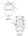
- FIG. 1 A fuel tank valve according to an existing design is shown in Figure 1 (with a cross sectional profile shown in Figure 1b ).
- the valve 10 comprises a valve body 12 having a generally cylindrical profile so as to define a central bore through which fluid may flow.
- a telescopic seal member 14 is received within the valve body and extends the central bore beyond the external surface 24 of the valve body 12.
- the telescopic seal member 14 is biased towards an extended position by a spring 18.
- the spring is intended to be in a compressed state, as the telescopic seal member 14 is at least partial pressed back into the valve body 12.
- the spring provides a sealing force at the seal surfaces.
- the proximal i.e.
- the telescopic seal member 14 is provided with a seat 22 on its external surface for receiving an O-ring to seal against the internal surface of the valve body 12.
- the distal (i.e. external) end of the telescopic seal member 14 is provided with a resilient portion in the form of a compressible elastomer seal 20 which, in use, is intended to form a sealing engagement with a planar seal surface of the aircraft.
- the telescopic member 14 is arranged such that it has a degree of lateral freedom within the valve body. Specifically, a clearance gap is maintained between the telescopic seal member 14 and both the valve body 12 (for example between the seal seat 22 and the internal surface of the valve body 12) and the hole 26 in the outer surface 24 of the valve body.
- the telescopic seal member is provided with a tapered external profile which converges slightly towards its distal end.
- the telescopic seal member may for example be arranged such that it may tilt its.longitudinal axis by up to 5 degrees. This freedom is intended to allow the seal to both align with the aircraft seal surface when fitted to the aircraft and to accommodate any relative dynamic movement between the tank and aircraft during manoeuvres on the ground or in flight.
- Embodiments of the invention seek to provide a valve arrangement with an improved leak resistance and, in particular, an arrangement with an increased leak resistance during aircraft manoeuvers.
- a first aspect of the present invention provides a valve for connecting an external tank to an aircraft, the valve comprising:
- a pivotable seal carrier ensures that the seal assembly of the valve is able to accommodate relative angular movement between the tank and the aircraft seal surface at a location which is only a short distance from the valve mating surfaces. This acts to discourage the seal from tilting on the aircraft seal surface, which may otherwise result in partial seal opening.
- the distal end of the telescopic seal member and the seal carrier may be provided with complimentary bearing surfaces which enable the seal carrier to pivot relative to the telescopic seal member and provide a sealing surface between the seal carrier and the telescopic seal member.
- the distal end of the telescopic seal member comprises a generally convex bearing surface and the seal carrier comprises a complimentary concave bearing surface.
- the surfaces may be reverse such that the distal end of the telescopic seal member comprises a generally concave bearing surface and the seal carrier comprises a complimentary convex bearing surface.
- the seal carrier may have a single degree of freedom (for example by providing a radial bearing surface) which would typically be aligned with the expected plane of the flexure ' of the tank in use.
- a spherical bearing is provided between the seal carrier and the telescopic seal member (such that the seal member may align to any angular displacement of the tank).
- a spherical bearing may be arranged such that the seal carrier may rotate about its longitudinal axis and may thereby enable the seal carrier to accommodate rotational movement between the tank and the aircraft.
- a spherical bearing requires at least one of the complimentary bearing surfaces to have a substantially spherical surface profile.
- the other of the complimentary bearing surfaces may be substantially spherical, substantially conical (for example frustoconical) or simply a circumferential edge.
- the valve body may comprise an external surface which, in use, opposes a surface of an aircraft and wherein the surface is provided with a hole through which the telescopic seal member protrudes, said hole being dimensioned and sized to closely match the external profile of the telescopic seal member.
- the hole may be arranged to enable axial movement and/or rotation of the telescopic seal member about its longitudinal axis but will limit tilting of the telescopic seal member axis.
- the valve body may comprise a generally cylindrical body and the telescopic seal member may comprises a generally cylindrical body having an external diameter which is less that the internal diameter of the valve body so as to be received within the valve body.
- a seal may typically be provided between the internal surface of the valve body and the external surface of the telescopic seal member.
- the external surface of the telescopic seal may be provided with a valve seat which retains an o-ring in sealing engagement with the valve body.
- the valve seat may be dimensioned and sized to closely match the internal diameter of the valve body.
- a biasing means for example a spring, is typically disposed between the valve body and the telescopic seal member and arranged to bias the telescopic seal member toward an extended position.
- the seal carrier may comprise an abutment surface for engaging, in use, a seal surface on an aircraft.
- the abutment surface may comprise a seal seat.
- the abutment surface is substantially planar so as to allow the seal carrier to slide across the aircraft seal surface in the event of relative lateral displacement between the tank and the aircraft.
- the abutment surface may be provided with an O-ring which may be partially recessed into the abutment surface.
- the seal carrier may be generally annular.
- the seal carrier may be arranged to engage the distal end of the telescopic seal member.
- the seal carrier may resiliently engage the telescopic seal member, for example the seal carrier may be mounted on the telescopic seal member by a snap fit arrangement.
- the seal carrier and telescopic seal member may be provided with mutual engagement features to retain the seal carrier thereon, for example the mutual engagement features may comprise a complimentary tab and recess.
- the mutual engagement features may comprise a circumferential recess on the inner surface of the seal carrier and an outwardly extending tab on the outer surface of the distal end of the telescopic seal member arranged to engage the recess.
- a mechanical stop may be provided to limit the range of motion of the seal carrier with respect to the telescopic seal member.
- the mutual engagement features may be further configured to provide a stop to limit the range of motion of the seal carrier.
- the valve body and seal assembly may define a central bore (through which fluid flows in use) which may generally extend along the longitudinal axis of the valve.
- a valve engagement member may extend through the central bore, and shaped and configured to engage an opening mechanism of a valve on an aircraft.
- the seal carrier may be adapted for alignment, in use, with a planar aircraft seal surface or a non-planar aircraft seal surface.
- an external tank for an aircraft comprising a valve in accordance with embodiments of the invention.
- the external tank may be an aircraft fuel tank.
- the external tank may comprise a plurality of valves in accordance with embodiments of the invention.
- a valve 100 in accordance with an embodiment of the invention is shown in Figure 2 .
- the valve comprises a valve body 112 is formed from aluminium and has a substantially cylindrical body with a cylindrical internal surface which is arranged to receive a telescopic seal member 114.
- a central bore for the flow of fluid extends along the longitudinal axis of the valve body 112 and along the longitudinal axis of the telescopic seal member 114.
- the valve body 112 is provided with an outer annular channel 113, which surrounds the central bore, for accommodating the telescopic seal member 114 such that the diameter of the central bore may remain substantially constant throughout the valve.
- the telescopic seal member 114 comprises a cylindrical aluminium pipe and is arranged to extend from the body and, in use, to engage a seal surface on an aircraft in a sealing arrangement.
- a steel spring 118 is provided between the telescopic seal member 114 and the valve 112 so as to bias the telescopic seal member out of the valve body 112.
- the valve 100 further comprises a valve engagement member 116 which extends through the central bore of both the telescopic seal member and the valve body to engage a valve member on a complimentary valve part mounted on an aircraft. As best seen in Figure 2b , with the spring 118 is compressed and the telescopic seal member 114 partially retracted into the valve body 112 the engagement member 116 extends beyond the seal surface of the valve 100.
- a seal carrier 150 is disposed upon the distal end of the telescopic seal member 114.
- a spherical bearing 160 is provided between the seal carrier 150 and the telescopic seal member 114 such that the seal carrier 125 is pivotable relative to the telescopic seal member 114 to enable alignment with a seal surface of an aircraft.
- the arrangement of the seal carrier is explained in further detail below.
- the telescopic seal member 114 is arranged within the valve 100 such that it is held in axial alignment with the valve body 112. In particular, relative rotation of the axis of the telescopic seal member 114 is prevented by the provision of a hole 126 in the external surface 124 of the valve body 112 which is dimensioned and sized to closely match the external diameter of the telescopic seal member 114.
- the hole 126 and the telescopic seal member 114 could be arranged with a clearance fit such that the telescopic seal member can freely slide in an axial direction or rotate about its longitudinal axes but would be maintained in alignment.
- a seal arrangement 122 is provided at the proximal (internal) end of the telescopic member 114 and is also configured to help maintain the axial alignment of the telescopic seal member.
- the seal is provided between the external surface of the telescopic seal member 114 and the internal surface of the valve body 112 and comprises a seal seat 122 for receiving an O-ring.
- the seal seat is formed by a pair of radially extending circumferential ridges 112A and 112B on the external surface of the telescopic seal member 114.
- Each of the ridges 122A and 122B are sized so as to maintain the desired spacing between the telescopic seal member 114 and the valve body 112.
- a clearance fit may be provided between the seal seat 122 and the valve body 112 thereby maintaining the axial alignment of the telescopic seal member and the valve body.
- the seal carrier 150 and the external distal end of the telescopic seal member 114 are provided with complimentary profiles which allow the seal carrier to be retained on the telescopic seal member 114 while also allowing rotation of the seal carrier with respect to the telescopic seal member 114.
- the seal carrier 150 is typically formed from a plastic material, for example nylon, such that it may resiliently engage the telescopic seal member 114.
- the seal carrier is, therefore, a "snap-fit" arrangement which undergoes plastic deformation in order to pass over a mutual engagement feature on the telescopic seal member 114 and to be retained thereon.
- the seal carrier 150 has a generally annular profile and is provided with a substantially planar abutment surface 154 which is arranged to engage a seal surface of an aircraft in use.
- the abutment surface 154 typically comprises a recessed seal seat 156 for receiving and captivating an O-ring 152.
- the seal seat may be provided with a profile which converges as the recess extends towards the abutment surface 154 such that an O-ring may be inserted into the seal seat by plastic deformation before being retained therein (as shown in Figure 3b ).
- the abutment surface 154 forms the outer boundary of a mouth 172 which is connected to the central bore of the valve 100.
- the inner surface of the seal carrier 150 Adjacent to the mouth 172 the inner surface of the seal carrier 150 is provided with a convex surface in the form of a frustoconical bearing surface 170.
- the bearing surface 170 terminates at an outwardly extending circumferential recess 174 which is partially closed by an inwardly radially projecting circumferential wall 176 which forms the proximal end of the seal carrier 150.
- the distal end of the telescopic seal member 114 is provided with a convex surface in the form of a spherical bearing surface 180 which is arranged to have a complimentary profile to the conical bearing surface 170 of the seal carrier 150.
- the spherical bearing surface 180 extends a short distance from the tip of the telescopic seal member 114 and terminates at an inwardly extending circumferential recess 184.
- the transition between the spherical bearing surface 180 and the external circumferential recess 184 forms a tab 182 which comprises a substantially radially extending wall.
- the recess 184 and tab 182 of the telescopic seal member have a complimentary profile to the wall 176 and recess 174 of the seal carrier 150 so as to provide mutual engagement features.
- the seal carrier 150 may be installed upon the telescopic seal member 114 (as shown in Figure 3b ) by plastic deformation as the inwardly projecting wall 176 of the seal carrier 150 deflects outwardly as it slides across the spherical bearing surface 180 of the telescopic seal member 180 before returning to its non-deformed position within the recess 184.
- the tab 182 and wall 176 prevent removal of the seal carrier 150 and also act to provide a physical stop which limits the extent to which the seal carrier 150 is able to rotate with respect to the telescopic seal member 114 (this may be seen on the left hand side of the seal carrier 150 in Figure 2b which has reached the limit of its range of motion).
- the cooperating features of the seal carrier 150 and the telescopic seal member 114 are typically circumferentially continuous, it will be appreciated that they could be formed from a plurality of sections, for example the tab 182 could be formed of a number of discrete tab sections spaced around the periphery of the telescopic seal member 114.
- the valve is mounted to an aircraft such that the abutment surface 154 of the seal carrier 150 engages a seal surface of the aircraft.
- the aircraft seal surface is substantially planar and surrounds a spring loaded valve which is biased towards a normally closed position.
- the first contact between the valve 100 and the aircraft is between the seal surface of the aircraft and the seal carrier 150 which may pivot in any direction relative to the axis of the valve 100 to align with the aircraft seal surface.
- the valve surfaces are compressed against each other to provide a good sealing engagement and the spring 118 is compressed as the telescopic seal member 114 is partially retracted into the valve body 112 (for example to the position shown in figure 2b ).
- the extent to which the telescopic seal member is retracted may depend upon the particular mounting that the external tank is being used for. As the telescopic seal member 114 retracts the valve engagement member 116 begins to protrude beyond the plane of the abutment surface 154 of the seal carrier 150 (which is the plane of aircraft seal surface). Thus, the valve engagement member 114 may engage the spring loaded valve on the aircraft and move it to an open position such that the valve of the fuel tank and the aircraft valve are placed in fluid communication. In the event of movement between the tank and aircraft (for example during aircraft manoeuvres) the seal is able retain sealing engagement whilst accommodating the movement.
- axial movement is accommodated by movement between the telescopic seal member and the valve body; rotational or tilting movement is accommodated by the movement of the spherical bearing between the seal carrier and the telescopic member; and lateral movement is accommodated by sliding between the parallel aligned sealing surfaces of the seal carrier and the aircraft seal surface.
- Figure 4 shows an alternate seal assembly 400 which may be used in alternate embodiments.
- the seal assembly 400 is equivalent to that of the earlier embodiment but uses a reverse orientated spherical bearing arrangement 460 between the seal carrier 450 and telescopic seal member 414.
- the telescopic seal member 460 is provided with a concave bearing surface and the seal carrier 450 is provided with a convex bearing surface.
- the convex surface would typically be spherical and the concave surface frustoconical.
- Figure 5 shows an alternate seal assembly 500 which may be used in further embodiments.
- the seal assembly 500 in this embodiment is provided with a radial bearing surface 560 between the between the seal carrier 550 and telescopic seal member 514.
- This arrangement limits the movement of the seal carrier to pivoting in a single plane. Rotational movement between in this arrangement is also limited compared to embodiments using spherical bearings since rotation movement is accommodated by rotation of the telescopic seal member 514 relative to the valve body. This rotational movement must overcome the frictional forces of the seals (as indicated by locations A and B on figure 5 ) and rotational resistance of the spring 518.
- the spherical bearing of the preferred embodiment consists of the combination of a spherical and a frustoconical bearing surface. This provides a line contact between the bearing surfaces and reduces the tolerances required in manufacturing of the surfaces (with the key requirement being only that the mating surfaces have a good surface quality).
- a frustoconical bearing surface also provides a more wear resistant bearing than a circumferential edge contact arrangement.
- valve body according to embodiments of the invention may be substantially identical to the valve body of existing designs. Accordingly, a seal assembly according to embodiments of the invention may be retrofitted to an existing valve body to provide a valve in accordance with the invention.
Landscapes
- Engineering & Computer Science (AREA)
- General Engineering & Computer Science (AREA)
- Mechanical Engineering (AREA)
- Aviation & Aerospace Engineering (AREA)
- Lift Valve (AREA)
Claims (14)
- Soupape (100) pour raccorder un réservoir externe à un aéronef, la soupape comprenant :un corps de soupape (112) ; etun ensemble d'étanchéité aménagé en service pour s'engager de manière élastique sur une surface d'étanchéité sur un aéronef, l'ensemble d'étanchéité comprenant :un élément d'étanchéité télescopique (114) s'étendant d'une extrémité proximale dans le corps de soupape (112) à une extrémité proximale, l'élément d'étanchéité télescopique étant contraint dans le corps de soupape de manière à maintenir l'alignement axial de l'élément d'étanchéité télescopique et du corps de soupape (112) ; etun support de joint étanche (150), caractérisé en ce qu'il est disposé à l'extrémité distale de l'élément d'étanchéité télescopique (114), le support de joint étanche (150) pouvant pivoter par rapport à l'élément d'étanchéité télescopique (114) pour un alignement en service avec la surface d'étanchéité de l'aéronef.
- Soupape (100) selon la revendication 1, dans laquelle l'extrémité distale de l'élément d'étanchéité télescopique (114) comprend une surface de palier généralement convexe (180) et le support de joint étanche (150) comprend une surface de palier concave complémentaire (170).
- Soupape (100) selon la revendication 1 ou la revendication 2, dans laquelle un palier sphérique est disposé entre le support de joint étanche (150) et l'élément d'étanchéité télescopique (114).
- Soupape (100) selon l'une quelconque des revendications précédentes, dans laquelle le corps de soupape (112) comprend en outre une surface externe qui, en service, est en regard d'une surface d'un aéronef et dans laquelle la surface est pourvue d'un trou (126) à travers lequel l'élément d'étanchéité télescopique (114) fait saillie, ledit trou étant dimensionné et calibré pour correspondre étroitement au profil externe de l'élément d'étanchéité télescopique (114).
- Soupape (100) selon l'une quelconque des revendications précédentes, dans laquelle le corps de soupape (112) comprend un corps généralement cylindrique et l'élément d'étanchéité télescopique (114) comprend un corps généralement cylindrique ayant un diamètre externe qui est inférieur du diamètre interne du corps de soupape (112) de manière à être reçu dans le corps de soupape.
- Soupape (100) selon la revendication 5, dans laquelle un joint étanche (122) est disposé entre la surface interne du corps de soupape (112) et la surface externe de l'élément d'étanchéité télescopique (114).
- Soupape (100) selon l'une quelconque des revendications précédentes, comprenant en outre un moyen de sollicitation (18) disposé entre le corps de soupape (112) et l'élément d'étanchéité télescopique (114) et aménagé pour presser l'élément d'étanchéité télescopique (114) vers une position d'extension.
- Soupape (100) selon l'une quelconque des revendications précédentes, dans laquelle le support de joint étanche (150) comprend en outre une surface de butée (154) pour s'engager en service sur une surface d'étanchéité d'un aéronef et dans lequel la surface de butée comprend un siège de joint étanche (152).
- Soupape (100) selon l'une quelconque des revendications précédentes, dans laquelle le support de joint étanche (150) est généralement annulaire et est aménagé pour s'engager de manière élastique sur l'extrémité distale de l'élément d'étanchéité télescopique (114).
- Soupape (100) selon la revendication 9, dans lequel le support de joint étanche (150) et l'élément d'étanchéité télescopique (114) sont pourvus de dispositifs d'engagement mutuel (184, 182 ; 176, 174) pour retenir le support de joint étanche (150).
- Soupape selon la revendication 10, dans laquelle les dispositifs d'engagement mutuel comprennent une cavité circonférentielle (174) sur la surface interne du support de joint étanche (150) et une patte (182) s'étendant vers l'extérieur sur la surface externe de l'extrémité distale de l'élément d'étanchéité télescopique (114) aménagée pour s'engager dans la cavité (174).
- Soupape (100) selon la revendication 10 ou la revendication 11, dans laquelle les dispositifs d'engagement mutuel sont en outre configurés pour fournir un arrêt permettant de limiter la plage de déplacement du support de joint étanche (150).
- Soupape selon l'une quelconque des revendications précédentes, comprenant en outre un élément d'engagement de soupape (116) s'étendant à travers un alésage central, défini par le corps de soupape et l'ensemble d'étanchéité et formé et configuré pour s'engager dans un mécanisme d'ouverture d'une soupape sur un aéronef.
- Réservoir externe pour un aéronef comprenant une soupape (100) selon l'une quelconque des revendications précédentes.
Applications Claiming Priority (2)
| Application Number | Priority Date | Filing Date | Title |
|---|---|---|---|
| GBGB1213626.3A GB201213626D0 (en) | 2012-07-31 | 2012-07-31 | Valve for an aircraft |
| PCT/EP2013/064798 WO2014019833A2 (fr) | 2012-07-31 | 2013-07-12 | Soupape pour un aéronef |
Publications (2)
| Publication Number | Publication Date |
|---|---|
| EP2879956A2 EP2879956A2 (fr) | 2015-06-10 |
| EP2879956B1 true EP2879956B1 (fr) | 2016-04-27 |
Family
ID=46881454
Family Applications (1)
| Application Number | Title | Priority Date | Filing Date |
|---|---|---|---|
| EP13736579.7A Not-in-force EP2879956B1 (fr) | 2012-07-31 | 2013-07-12 | Soupape pour un reservoir ejectable d'aéronef |
Country Status (8)
| Country | Link |
|---|---|
| US (1) | US9926083B2 (fr) |
| EP (1) | EP2879956B1 (fr) |
| CN (1) | CN104507811B (fr) |
| BR (1) | BR112015002305A2 (fr) |
| CA (1) | CA2880112A1 (fr) |
| GB (1) | GB201213626D0 (fr) |
| RU (1) | RU2636236C2 (fr) |
| WO (1) | WO2014019833A2 (fr) |
Families Citing this family (4)
| Publication number | Priority date | Publication date | Assignee | Title |
|---|---|---|---|---|
| WO2018188054A1 (fr) * | 2017-04-14 | 2018-10-18 | 深圳市方鹏科技有限公司 | Système de largage séparé de réservoir de carburant destiné à un véhicule aérien sans pilote |
| NO344856B1 (en) * | 2018-10-19 | 2020-06-02 | Vetco Gray Scandinavia As | Misalignment Accommodating Hydraulic Coupler |
| CN109533357A (zh) * | 2018-11-14 | 2019-03-29 | 中国直升机设计研究所 | 一种用于直升机燃油箱抗坠毁的易断自封接头 |
| CN111099028B (zh) * | 2019-12-26 | 2021-04-06 | 燕山大学 | 一种模块化飞机应急减重安全油箱及其控制方法 |
Family Cites Families (36)
| Publication number | Priority date | Publication date | Assignee | Title |
|---|---|---|---|---|
| US1345571A (en) * | 1917-02-07 | 1920-07-06 | Isko Company | Pipe-coupling |
| US1547483A (en) * | 1924-04-11 | 1925-07-28 | Leonidas D Woodruff | Double-pivoted ball joint |
| US1651522A (en) * | 1924-11-20 | 1927-12-06 | Gold Car Heating & Lighting Co | Pipe joint |
| US1681626A (en) * | 1925-01-19 | 1928-08-21 | Vapor Car Heating Co Inc | Flexible pipe joint |
| US1714142A (en) * | 1928-07-12 | 1929-05-21 | Arthur J Schmitt | Gasket and seat therefor |
| US2071750A (en) * | 1935-06-07 | 1937-02-23 | Westinghouse Air Brake Co | Pipe coupling gasket |
| US2362880A (en) * | 1942-10-24 | 1944-11-14 | Stewart Warner Corp | Coupler |
| US2427456A (en) * | 1944-02-12 | 1947-09-16 | Thomas J Hoy | Joint |
| US2582609A (en) * | 1949-03-30 | 1952-01-15 | Curtiss Wright Corp | Means for fueling aircraft in flight |
| US2686529A (en) * | 1950-04-05 | 1954-08-17 | Lanninger Karl Ludwig | Movable pipe line |
| US2731278A (en) * | 1953-06-09 | 1956-01-17 | Boeing Co | Self-sealing releasable coupling |
| US3129718A (en) * | 1959-12-28 | 1964-04-21 | Curtis Automotive Devices Inc | Valve with means for limiting seal flexure |
| US3089714A (en) * | 1960-03-23 | 1963-05-14 | Fred E Croy | Bellows contained within a composite ball in a socket |
| US3107107A (en) * | 1960-08-22 | 1963-10-15 | Atlas Copco Ab | Rotary swivel fluid coupling |
| DE1195606B (de) * | 1962-07-03 | 1965-06-24 | Dornier Werke Gmbh | Leitungsanschluss fuer abwerfbare Behaelter fuer fluessige und/oder gasfoermige Medien |
| US3227475A (en) * | 1963-05-22 | 1966-01-04 | North American Aviation Inc | Conduit construction |
| US3319979A (en) * | 1964-04-03 | 1967-05-16 | Curt P Herold | Quick attach and release fluid coupling assembly |
| US3664634A (en) * | 1968-09-19 | 1972-05-23 | Robert W Guertin | Valve seal for coupling device |
| US3670770A (en) * | 1970-05-01 | 1972-06-20 | Int Harvester Co | Fluid line coupling |
| US3938564A (en) * | 1975-01-06 | 1976-02-17 | Kaiser Aerospace And Electronics Corporation | Quick-release fuel coupling for racing cars |
| US4306693A (en) * | 1977-05-04 | 1981-12-22 | Cooper Isaac B | Aircraft with jettisonable fuel tank means |
| US4296952A (en) * | 1979-07-30 | 1981-10-27 | Aeroquip Corporation | Rotary joint |
| US4378945A (en) * | 1981-01-29 | 1983-04-05 | Paccar Inc. | Bellows-type spring seal |
| DE3508732A1 (de) * | 1985-03-12 | 1986-09-25 | M A N Nutzfahrzeuge GmbH, 8000 München | Stroemungsmitteldichte leitungsverbindung |
| FR2591293B1 (fr) * | 1985-12-11 | 1989-09-01 | Inst Francais Du Petrole | Support elastique a rotule adapte en particulier a des utilisations pour des navires ou des plates-formes flottantes en mer. |
| US4790350A (en) * | 1986-02-04 | 1988-12-13 | Arnold Charles M | Combat rapid assembly fuel tank |
| US4892171A (en) * | 1988-09-12 | 1990-01-09 | Scheindel Christian T | Adapter for use with a lubrication fitting |
| RU2021168C1 (ru) * | 1992-04-10 | 1994-10-15 | Товарищество с ограниченной ответственностью "Аэротон" | Способ выработки топлива из баков летательного аппарата и топливная система летательного аппарата |
| FR2705130B1 (fr) * | 1993-05-12 | 1995-06-23 | Snecma | Organe de distribution de fluide avec siege auto-centreur. |
| US5657963A (en) * | 1993-06-16 | 1997-08-19 | United States Surgical Corporation | Seal assembly for accommodating introduction of surgical instruments |
| DK137593D0 (da) * | 1993-12-09 | 1993-12-09 | Micro Matic As | Spaerrearrangement |
| US5810292A (en) * | 1996-07-24 | 1998-09-22 | Sargent Fletcher, Inc. | Aerial refueling system with telescoping refueling probe |
| US6019348A (en) * | 1997-09-08 | 2000-02-01 | Dana Corporation | Quick-connection of a fuel fill pipe to a fuel tank |
| RU2313025C1 (ru) * | 2006-05-18 | 2007-12-20 | Открытое Акционерное Общество "Государственное Машиностроительное Конструкторское Бюро "Радуга" Имени А.Я. Березняка" | Дренажный клапан топливного бака летательного аппарата |
| RU2385271C1 (ru) * | 2008-12-11 | 2010-03-27 | Открытое Акционерное Общество "Государственное Машиностроительное Конструкторское Бюро "Радуга" Имени А.Я. Березняка" | Клапан топливного бака летательного аппарата |
| US20110129292A1 (en) * | 2009-12-01 | 2011-06-02 | Wan-Bau Chen | Universal coupling |
-
2012
- 2012-07-31 GB GBGB1213626.3A patent/GB201213626D0/en not_active Ceased
-
2013
- 2013-07-12 CN CN201380040393.2A patent/CN104507811B/zh not_active Expired - Fee Related
- 2013-07-12 RU RU2015106976A patent/RU2636236C2/ru active
- 2013-07-12 US US14/417,828 patent/US9926083B2/en active Active
- 2013-07-12 WO PCT/EP2013/064798 patent/WO2014019833A2/fr not_active Ceased
- 2013-07-12 BR BR112015002305A patent/BR112015002305A2/pt active Search and Examination
- 2013-07-12 EP EP13736579.7A patent/EP2879956B1/fr not_active Not-in-force
- 2013-07-12 CA CA2880112A patent/CA2880112A1/fr not_active Abandoned
Also Published As
| Publication number | Publication date |
|---|---|
| WO2014019833A3 (fr) | 2014-03-27 |
| EP2879956A2 (fr) | 2015-06-10 |
| BR112015002305A2 (pt) | 2017-07-04 |
| WO2014019833A2 (fr) | 2014-02-06 |
| CA2880112A1 (fr) | 2014-02-06 |
| CN104507811A (zh) | 2015-04-08 |
| CN104507811B (zh) | 2017-06-30 |
| US9926083B2 (en) | 2018-03-27 |
| GB201213626D0 (en) | 2012-09-12 |
| US20150210403A1 (en) | 2015-07-30 |
| RU2636236C2 (ru) | 2017-11-21 |
| RU2015106976A (ru) | 2016-09-20 |
Similar Documents
| Publication | Publication Date | Title |
|---|---|---|
| US6899132B2 (en) | Fluid coupler | |
| EP2879956B1 (fr) | Soupape pour un reservoir ejectable d'aéronef | |
| US6877778B2 (en) | Linearly actuated quick connect pipe couplings | |
| US7309083B2 (en) | Female connection element and quick connection incorporating such an element | |
| ES2440325T3 (es) | Sistema de enclavamiento para un acoplamiento de válvula | |
| CN116164127A (zh) | 阀座、阀组件以及在球阀中设置密封件的方法 | |
| US8251407B2 (en) | Female coupling element and a quick coupling incorporating such an element | |
| CN102261488B (zh) | 球阀座密封件 | |
| US20090252443A1 (en) | Spherical bearing for a steering joint | |
| US20100201123A1 (en) | Pipe coupling and female pipe coupling member | |
| CN102459939B (zh) | 球轴承、包括该球轴承的离合器止推轴承和装有该轴承的汽车 | |
| JP6490007B2 (ja) | 高圧用トラニオン型ボール弁およびこれを用いた水素ステーション | |
| US20170074443A1 (en) | High-Pressure Bi-Directional Sealing System | |
| EP2626599A1 (fr) | Raccord rapide à verrou de dégagement | |
| US20040103946A1 (en) | Coupling assembly having a coupling member removably securable in an apparatus | |
| EP1875093B1 (fr) | Roulement etanche | |
| JP6474262B2 (ja) | トラニオン型ボールバルブ | |
| US20050087241A1 (en) | Coupling member of a pipe coupling | |
| CA2088508C (fr) | Dispositifs amortisseurs pour appareils de regulation | |
| US8316733B2 (en) | Rotational coupling device | |
| EP3388702A1 (fr) | Ensemble d'étanchéité en deux parties pour un palier de galet de roulement | |
| US8672290B2 (en) | Self aligning spherical backseat assembly for a valve | |
| CN108692045A (zh) | 用于工业闸阀的密封组件和包括该密封组件的阀 | |
| US6722131B1 (en) | Fuel control valve | |
| CA3084447C (fr) | Joint d'etancheite avec profile de retenue |
Legal Events
| Date | Code | Title | Description |
|---|---|---|---|
| PUAI | Public reference made under article 153(3) epc to a published international application that has entered the european phase |
Free format text: ORIGINAL CODE: 0009012 |
|
| 17P | Request for examination filed |
Effective date: 20150126 |
|
| AK | Designated contracting states |
Kind code of ref document: A2 Designated state(s): AL AT BE BG CH CY CZ DE DK EE ES FI FR GB GR HR HU IE IS IT LI LT LU LV MC MK MT NL NO PL PT RO RS SE SI SK SM TR |
|
| AX | Request for extension of the european patent |
Extension state: BA ME |
|
| DAX | Request for extension of the european patent (deleted) | ||
| REG | Reference to a national code |
Ref country code: DE Ref legal event code: R079 Ref document number: 602013007113 Country of ref document: DE Free format text: PREVIOUS MAIN CLASS: B64D0037120000 Ipc: F16K0027000000 |
|
| GRAP | Despatch of communication of intention to grant a patent |
Free format text: ORIGINAL CODE: EPIDOSNIGR1 |
|
| RIC1 | Information provided on ipc code assigned before grant |
Ipc: F16K 27/00 20060101AFI20151113BHEP |
|
| INTG | Intention to grant announced |
Effective date: 20151130 |
|
| GRAS | Grant fee paid |
Free format text: ORIGINAL CODE: EPIDOSNIGR3 |
|
| GRAA | (expected) grant |
Free format text: ORIGINAL CODE: 0009210 |
|
| AK | Designated contracting states |
Kind code of ref document: B1 Designated state(s): AL AT BE BG CH CY CZ DE DK EE ES FI FR GB GR HR HU IE IS IT LI LT LU LV MC MK MT NL NO PL PT RO RS SE SI SK SM TR |
|
| REG | Reference to a national code |
Ref country code: GB Ref legal event code: FG4D |
|
| REG | Reference to a national code |
Ref country code: CH Ref legal event code: EP |
|
| REG | Reference to a national code |
Ref country code: AT Ref legal event code: REF Ref document number: 795191 Country of ref document: AT Kind code of ref document: T Effective date: 20160515 |
|
| REG | Reference to a national code |
Ref country code: IE Ref legal event code: FG4D |
|
| REG | Reference to a national code |
Ref country code: DE Ref legal event code: R096 Ref document number: 602013007113 Country of ref document: DE |
|
| REG | Reference to a national code |
Ref country code: FR Ref legal event code: PLFP Year of fee payment: 4 |
|
| REG | Reference to a national code |
Ref country code: NL Ref legal event code: FP |
|
| REG | Reference to a national code |
Ref country code: LT Ref legal event code: MG4D |
|
| REG | Reference to a national code |
Ref country code: AT Ref legal event code: MK05 Ref document number: 795191 Country of ref document: AT Kind code of ref document: T Effective date: 20160427 |
|
| PG25 | Lapsed in a contracting state [announced via postgrant information from national office to epo] |
Ref country code: NO Free format text: LAPSE BECAUSE OF FAILURE TO SUBMIT A TRANSLATION OF THE DESCRIPTION OR TO PAY THE FEE WITHIN THE PRESCRIBED TIME-LIMIT Effective date: 20160727 Ref country code: PL Free format text: LAPSE BECAUSE OF FAILURE TO SUBMIT A TRANSLATION OF THE DESCRIPTION OR TO PAY THE FEE WITHIN THE PRESCRIBED TIME-LIMIT Effective date: 20160427 Ref country code: LT Free format text: LAPSE BECAUSE OF FAILURE TO SUBMIT A TRANSLATION OF THE DESCRIPTION OR TO PAY THE FEE WITHIN THE PRESCRIBED TIME-LIMIT Effective date: 20160427 Ref country code: FI Free format text: LAPSE BECAUSE OF FAILURE TO SUBMIT A TRANSLATION OF THE DESCRIPTION OR TO PAY THE FEE WITHIN THE PRESCRIBED TIME-LIMIT Effective date: 20160427 |
|
| PG25 | Lapsed in a contracting state [announced via postgrant information from national office to epo] |
Ref country code: AT Free format text: LAPSE BECAUSE OF FAILURE TO SUBMIT A TRANSLATION OF THE DESCRIPTION OR TO PAY THE FEE WITHIN THE PRESCRIBED TIME-LIMIT Effective date: 20160427 Ref country code: GR Free format text: LAPSE BECAUSE OF FAILURE TO SUBMIT A TRANSLATION OF THE DESCRIPTION OR TO PAY THE FEE WITHIN THE PRESCRIBED TIME-LIMIT Effective date: 20160728 Ref country code: LV Free format text: LAPSE BECAUSE OF FAILURE TO SUBMIT A TRANSLATION OF THE DESCRIPTION OR TO PAY THE FEE WITHIN THE PRESCRIBED TIME-LIMIT Effective date: 20160427 Ref country code: SE Free format text: LAPSE BECAUSE OF FAILURE TO SUBMIT A TRANSLATION OF THE DESCRIPTION OR TO PAY THE FEE WITHIN THE PRESCRIBED TIME-LIMIT Effective date: 20160427 Ref country code: PT Free format text: LAPSE BECAUSE OF FAILURE TO SUBMIT A TRANSLATION OF THE DESCRIPTION OR TO PAY THE FEE WITHIN THE PRESCRIBED TIME-LIMIT Effective date: 20160829 Ref country code: HR Free format text: LAPSE BECAUSE OF FAILURE TO SUBMIT A TRANSLATION OF THE DESCRIPTION OR TO PAY THE FEE WITHIN THE PRESCRIBED TIME-LIMIT Effective date: 20160427 Ref country code: RS Free format text: LAPSE BECAUSE OF FAILURE TO SUBMIT A TRANSLATION OF THE DESCRIPTION OR TO PAY THE FEE WITHIN THE PRESCRIBED TIME-LIMIT Effective date: 20160427 Ref country code: ES Free format text: LAPSE BECAUSE OF FAILURE TO SUBMIT A TRANSLATION OF THE DESCRIPTION OR TO PAY THE FEE WITHIN THE PRESCRIBED TIME-LIMIT Effective date: 20160427 |
|
| PG25 | Lapsed in a contracting state [announced via postgrant information from national office to epo] |
Ref country code: BE Free format text: LAPSE BECAUSE OF FAILURE TO SUBMIT A TRANSLATION OF THE DESCRIPTION OR TO PAY THE FEE WITHIN THE PRESCRIBED TIME-LIMIT Effective date: 20160427 |
|
| REG | Reference to a national code |
Ref country code: DE Ref legal event code: R097 Ref document number: 602013007113 Country of ref document: DE |
|
| PG25 | Lapsed in a contracting state [announced via postgrant information from national office to epo] |
Ref country code: EE Free format text: LAPSE BECAUSE OF FAILURE TO SUBMIT A TRANSLATION OF THE DESCRIPTION OR TO PAY THE FEE WITHIN THE PRESCRIBED TIME-LIMIT Effective date: 20160427 Ref country code: SK Free format text: LAPSE BECAUSE OF FAILURE TO SUBMIT A TRANSLATION OF THE DESCRIPTION OR TO PAY THE FEE WITHIN THE PRESCRIBED TIME-LIMIT Effective date: 20160427 Ref country code: DK Free format text: LAPSE BECAUSE OF FAILURE TO SUBMIT A TRANSLATION OF THE DESCRIPTION OR TO PAY THE FEE WITHIN THE PRESCRIBED TIME-LIMIT Effective date: 20160427 Ref country code: RO Free format text: LAPSE BECAUSE OF FAILURE TO SUBMIT A TRANSLATION OF THE DESCRIPTION OR TO PAY THE FEE WITHIN THE PRESCRIBED TIME-LIMIT Effective date: 20160427 Ref country code: CZ Free format text: LAPSE BECAUSE OF FAILURE TO SUBMIT A TRANSLATION OF THE DESCRIPTION OR TO PAY THE FEE WITHIN THE PRESCRIBED TIME-LIMIT Effective date: 20160427 |
|
| PG25 | Lapsed in a contracting state [announced via postgrant information from national office to epo] |
Ref country code: SM Free format text: LAPSE BECAUSE OF FAILURE TO SUBMIT A TRANSLATION OF THE DESCRIPTION OR TO PAY THE FEE WITHIN THE PRESCRIBED TIME-LIMIT Effective date: 20160427 |
|
| REG | Reference to a national code |
Ref country code: CH Ref legal event code: PL |
|
| PLBE | No opposition filed within time limit |
Free format text: ORIGINAL CODE: 0009261 |
|
| STAA | Information on the status of an ep patent application or granted ep patent |
Free format text: STATUS: NO OPPOSITION FILED WITHIN TIME LIMIT |
|
| PG25 | Lapsed in a contracting state [announced via postgrant information from national office to epo] |
Ref country code: MC Free format text: LAPSE BECAUSE OF FAILURE TO SUBMIT A TRANSLATION OF THE DESCRIPTION OR TO PAY THE FEE WITHIN THE PRESCRIBED TIME-LIMIT Effective date: 20160427 |
|
| 26N | No opposition filed |
Effective date: 20170130 |
|
| PG25 | Lapsed in a contracting state [announced via postgrant information from national office to epo] |
Ref country code: LI Free format text: LAPSE BECAUSE OF NON-PAYMENT OF DUE FEES Effective date: 20160731 Ref country code: CH Free format text: LAPSE BECAUSE OF NON-PAYMENT OF DUE FEES Effective date: 20160731 |
|
| REG | Reference to a national code |
Ref country code: IE Ref legal event code: MM4A |
|
| PG25 | Lapsed in a contracting state [announced via postgrant information from national office to epo] |
Ref country code: SI Free format text: LAPSE BECAUSE OF FAILURE TO SUBMIT A TRANSLATION OF THE DESCRIPTION OR TO PAY THE FEE WITHIN THE PRESCRIBED TIME-LIMIT Effective date: 20160427 |
|
| REG | Reference to a national code |
Ref country code: FR Ref legal event code: PLFP Year of fee payment: 5 |
|
| PG25 | Lapsed in a contracting state [announced via postgrant information from national office to epo] |
Ref country code: IE Free format text: LAPSE BECAUSE OF NON-PAYMENT OF DUE FEES Effective date: 20160712 |
|
| PG25 | Lapsed in a contracting state [announced via postgrant information from national office to epo] |
Ref country code: LU Free format text: LAPSE BECAUSE OF NON-PAYMENT OF DUE FEES Effective date: 20160712 |
|
| GBPC | Gb: european patent ceased through non-payment of renewal fee |
Effective date: 20170712 |
|
| PG25 | Lapsed in a contracting state [announced via postgrant information from national office to epo] |
Ref country code: GB Free format text: LAPSE BECAUSE OF NON-PAYMENT OF DUE FEES Effective date: 20170712 |
|
| PG25 | Lapsed in a contracting state [announced via postgrant information from national office to epo] |
Ref country code: HU Free format text: LAPSE BECAUSE OF FAILURE TO SUBMIT A TRANSLATION OF THE DESCRIPTION OR TO PAY THE FEE WITHIN THE PRESCRIBED TIME-LIMIT; INVALID AB INITIO Effective date: 20130712 |
|
| REG | Reference to a national code |
Ref country code: FR Ref legal event code: PLFP Year of fee payment: 6 |
|
| PG25 | Lapsed in a contracting state [announced via postgrant information from national office to epo] |
Ref country code: CY Free format text: LAPSE BECAUSE OF FAILURE TO SUBMIT A TRANSLATION OF THE DESCRIPTION OR TO PAY THE FEE WITHIN THE PRESCRIBED TIME-LIMIT Effective date: 20160427 Ref country code: MT Free format text: LAPSE BECAUSE OF NON-PAYMENT OF DUE FEES Effective date: 20160731 Ref country code: MK Free format text: LAPSE BECAUSE OF FAILURE TO SUBMIT A TRANSLATION OF THE DESCRIPTION OR TO PAY THE FEE WITHIN THE PRESCRIBED TIME-LIMIT Effective date: 20160427 Ref country code: IS Free format text: LAPSE BECAUSE OF FAILURE TO SUBMIT A TRANSLATION OF THE DESCRIPTION OR TO PAY THE FEE WITHIN THE PRESCRIBED TIME-LIMIT Effective date: 20160427 |
|
| PG25 | Lapsed in a contracting state [announced via postgrant information from national office to epo] |
Ref country code: BG Free format text: LAPSE BECAUSE OF FAILURE TO SUBMIT A TRANSLATION OF THE DESCRIPTION OR TO PAY THE FEE WITHIN THE PRESCRIBED TIME-LIMIT Effective date: 20160427 |
|
| PG25 | Lapsed in a contracting state [announced via postgrant information from national office to epo] |
Ref country code: TR Free format text: LAPSE BECAUSE OF FAILURE TO SUBMIT A TRANSLATION OF THE DESCRIPTION OR TO PAY THE FEE WITHIN THE PRESCRIBED TIME-LIMIT Effective date: 20160427 Ref country code: AL Free format text: LAPSE BECAUSE OF FAILURE TO SUBMIT A TRANSLATION OF THE DESCRIPTION OR TO PAY THE FEE WITHIN THE PRESCRIBED TIME-LIMIT Effective date: 20160427 |
|
| REG | Reference to a national code |
Ref country code: DE Ref legal event code: R081 Ref document number: 602013007113 Country of ref document: DE Owner name: EATON INTELLIGENT POWER LIMITED, IE Free format text: FORMER OWNER: EATON LTD., TITCHFIELD, HAMPSHIRE, GB |
|
| PGFP | Annual fee paid to national office [announced via postgrant information from national office to epo] |
Ref country code: FR Payment date: 20210623 Year of fee payment: 9 Ref country code: IT Payment date: 20210622 Year of fee payment: 9 Ref country code: NL Payment date: 20210622 Year of fee payment: 9 |
|
| PGFP | Annual fee paid to national office [announced via postgrant information from national office to epo] |
Ref country code: DE Payment date: 20210622 Year of fee payment: 9 |
|
| REG | Reference to a national code |
Ref country code: DE Ref legal event code: R119 Ref document number: 602013007113 Country of ref document: DE |
|
| REG | Reference to a national code |
Ref country code: NL Ref legal event code: MM Effective date: 20220801 |
|
| PG25 | Lapsed in a contracting state [announced via postgrant information from national office to epo] |
Ref country code: FR Free format text: LAPSE BECAUSE OF NON-PAYMENT OF DUE FEES Effective date: 20220731 |
|
| PG25 | Lapsed in a contracting state [announced via postgrant information from national office to epo] |
Ref country code: DE Free format text: LAPSE BECAUSE OF NON-PAYMENT OF DUE FEES Effective date: 20230201 |
|
| PG25 | Lapsed in a contracting state [announced via postgrant information from national office to epo] |
Ref country code: NL Free format text: LAPSE BECAUSE OF NON-PAYMENT OF DUE FEES Effective date: 20220801 |
|
| PG25 | Lapsed in a contracting state [announced via postgrant information from national office to epo] |
Ref country code: IT Free format text: LAPSE BECAUSE OF NON-PAYMENT OF DUE FEES Effective date: 20220712 |