EP2880237B1 - Vacuum insulated glass (vig) window unit including hybrid getter and method of making same - Google Patents
Vacuum insulated glass (vig) window unit including hybrid getter and method of making same Download PDFInfo
- Publication number
- EP2880237B1 EP2880237B1 EP13742575.7A EP13742575A EP2880237B1 EP 2880237 B1 EP2880237 B1 EP 2880237B1 EP 13742575 A EP13742575 A EP 13742575A EP 2880237 B1 EP2880237 B1 EP 2880237B1
- Authority
- EP
- European Patent Office
- Prior art keywords
- getter
- neg
- substrate
- substrates
- activating
- Prior art date
- Legal status (The legal status is an assumption and is not a legal conclusion. Google has not performed a legal analysis and makes no representation as to the accuracy of the status listed.)
- Active
Links
Images


Classifications
-
- E—FIXED CONSTRUCTIONS
- E06—DOORS, WINDOWS, SHUTTERS, OR ROLLER BLINDS IN GENERAL; LADDERS
- E06B—FIXED OR MOVABLE CLOSURES FOR OPENINGS IN BUILDINGS, VEHICLES, FENCES OR LIKE ENCLOSURES IN GENERAL, e.g. DOORS, WINDOWS, BLINDS, GATES
- E06B3/00—Window sashes, door leaves, or like elements for closing wall or like openings; Layout of fixed or moving closures, e.g. windows in wall or like openings; Features of rigidly-mounted outer frames relating to the mounting of wing frames
- E06B3/66—Units comprising two or more parallel glass or like panes permanently secured together
- E06B3/6612—Evacuated glazing units
-
- E—FIXED CONSTRUCTIONS
- E06—DOORS, WINDOWS, SHUTTERS, OR ROLLER BLINDS IN GENERAL; LADDERS
- E06B—FIXED OR MOVABLE CLOSURES FOR OPENINGS IN BUILDINGS, VEHICLES, FENCES OR LIKE ENCLOSURES IN GENERAL, e.g. DOORS, WINDOWS, BLINDS, GATES
- E06B3/00—Window sashes, door leaves, or like elements for closing wall or like openings; Layout of fixed or moving closures, e.g. windows in wall or like openings; Features of rigidly-mounted outer frames relating to the mounting of wing frames
- E06B3/66—Units comprising two or more parallel glass or like panes permanently secured together
- E06B3/677—Evacuating or filling the gap between the panes ; Equilibration of inside and outside pressure; Preventing condensation in the gap between the panes; Cleaning the gap between the panes
- E06B3/6775—Evacuating or filling the gap during assembly
-
- Y—GENERAL TAGGING OF NEW TECHNOLOGICAL DEVELOPMENTS; GENERAL TAGGING OF CROSS-SECTIONAL TECHNOLOGIES SPANNING OVER SEVERAL SECTIONS OF THE IPC; TECHNICAL SUBJECTS COVERED BY FORMER USPC CROSS-REFERENCE ART COLLECTIONS [XRACs] AND DIGESTS
- Y02—TECHNOLOGIES OR APPLICATIONS FOR MITIGATION OR ADAPTATION AGAINST CLIMATE CHANGE
- Y02A—TECHNOLOGIES FOR ADAPTATION TO CLIMATE CHANGE
- Y02A30/00—Adapting or protecting infrastructure or their operation
- Y02A30/24—Structural elements or technologies for improving thermal insulation
- Y02A30/249—Glazing, e.g. vacuum glazing
-
- Y—GENERAL TAGGING OF NEW TECHNOLOGICAL DEVELOPMENTS; GENERAL TAGGING OF CROSS-SECTIONAL TECHNOLOGIES SPANNING OVER SEVERAL SECTIONS OF THE IPC; TECHNICAL SUBJECTS COVERED BY FORMER USPC CROSS-REFERENCE ART COLLECTIONS [XRACs] AND DIGESTS
- Y02—TECHNOLOGIES OR APPLICATIONS FOR MITIGATION OR ADAPTATION AGAINST CLIMATE CHANGE
- Y02B—CLIMATE CHANGE MITIGATION TECHNOLOGIES RELATED TO BUILDINGS, e.g. HOUSING, HOUSE APPLIANCES OR RELATED END-USER APPLICATIONS
- Y02B80/00—Architectural or constructional elements improving the thermal performance of buildings
- Y02B80/22—Glazing, e.g. vaccum glazing
Definitions
- This disclosure relates generally to an intermediate product for fabricating vacuum insulated glass (VIG) window units and methods for making VIG window units.
- the disclosure relates to an intermediate product for fabricating VIG window units including at least one hybrid getter, and methods of making the same.
- said hybrid getter includes both evaporable getter (EG) material and non-evaporable getter (NEG) material.
- the NEG material is at least partially covered (directly or indirectly) with EG material in the hybrid getter at least prior to getter activating/flashing.
- Vacuum insulating glass (VIG) window units typically include at least two spaced apart glass substrates that enclose an evacuated low-pressure space/cavity therebetween.
- the substrates are interconnected by a peripheral edge seal and typically include spacers between the glass substrates to maintain spacing between the glass substrates and to avoid collapse of the glass substrates that may be caused due to the low pressure evacuated environment that exists between the substrates.
- Some example VIG configurations are disclosed, for example, in U.S. Patent Nos. 5,657,607 , 5,664,395 , 5,657,607 , 5,902,652 , 6,506,472 and 6,383, 580 .
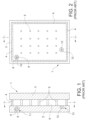
- VIG unit 1 may include two spaced apart substantially parallel glass substrates 2, 3, which enclose an evacuated low-pressure space/cavity 6 therebetween. Glass sheets or substrates 2, 3 are interconnected by a peripheral edge seal 4 which may be made of fused solder glass, for example, An array of support pillars/spacers 5 may be included between the glass substrates 2, 3 to maintain the spacing of glass substrates 2, 3 of the VIG unit 1 in view of the low-pressure space/gap 6 present between the substrates 2, 3.
- a pump-out tube 8 may be hermetically sealed by, for example, solder glass 9 to an aperture/hole 10 that passes from an interior surface of one of the glass substrates 2 to the bottom of an optional recess 11 in the exterior surface of the glass substrate 2, or optionally to the exterior surface of the glass substrate 2.
- a vacuum is attached to pump-out tube 8 to evacuate (e.g., pump-down) the interior cavity 6 to a low pressure that is less than atmospheric pressure. After evacuation of the cavity 6, a portion (e.g., the tip) of the tube 8 is melted to seal the vacuum in low pressure cavity/space 6.
- the optional recess 11 may retain the sealed pump-out tube 8.
- a getter 12 may be included within a recess 13 that is disposed in an interior face of one of the glass substrates, e.g., glass substrate 2.
- the getter 12 may be used to absorb and/or bind with certain residual impurities that may remain after the cavity 6 is evacuated and sealed.
- the getter is of or includes a mixture of metals that can react with gas(es) to hold gas(es) impurities to the gettering surface and/or dissolve such gas(es).
- WO 2004/039742 A1 describes a method of making a vacuum insulated glass window unit using a hybrid getter, which comprises non-evaporative getter material and evaporative getter material.
- a method of making a vacuum insulated glass (VIG) window unit comprising: having first and second substantially parallel substrates (e.g., substrates of or including glass), a plurality of spacers and a seal provided between the first and second substrates, and a cavity to be evacuated to a pressure less than atmospheric pressure located between the substrates, and a hybrid getter supported by the first substrate; the hyrid getter comprising non-evaporative getter (NEG) material and evaporative getter (EG) material, the EG material at least partially covering the NEG material; and activating the hybrid getter.
- first and second substantially parallel glass substrates 2 and 3 there is provided first and second substantially parallel glass substrates 2 and 3, a plurality of spacers 5 and a seal (e.g., edge seal) 4 provided between the first and second substrates, and a cavity 6 to be evacuated to a pressure less than atmospheric pressure located between the glass substrates 2 and 3.
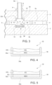
- a hybrid getter 32 is supported by substrate 2, the hyrid getter including non-evaporative getter (NEG) material 32a and evaporative getter (EG) material 32b.
- the EG material 32b at least partially covers the NEG material 32a of the hybrid getter.
- the NEG material 32a and EG material 32b are provided in a container 38 (e.g., metallic or substantially metallic container, adapted for heating via a coil which may be used in activating the getter) supported by glass substrate 2, with the EG material 32b partially or fully covering the NEG material 32a in the container 38 so that the NEG material 32a is located between the EG material 32b and a base 38a of the container 38.
- the hybrid getter 32 may be located in a recess 14 defined in substrate 2.
- the hybrid getter 32 After seal material (e.g., frit) has been heated in order to form the edge seal 4, and during and/or after the evacuation process for evacuating cavity 6, the hybrid getter 32 is sufficiently heated so that it is activated/flashed. Prior to activating, the entire getter 32 is supported by substrate 2, and then activating/flashing of the hybrid getter causes at least some EG material 32b of the hybrid getter to evaporate and line-of-site deposit on at least a surface of the opposite substrate 3 (e.g., on an interior major surface of substrate 3, and/or in an optional recess 14' which may be defined in substrate 3).
- seal material e.g., frit
- Activating of the hybrid getter 32 is preferably performed by heating the hybrid getter 32 via a laser beam and/or via radiation from a coil (e.g., directing a laser beam through a pump-out tube 8 to activate the hybrid getter and/or directing radiation at the getter from a coil located outside the VIG unit). Activating is preferably performed during and/or after an evacuation process in which the cavity 6 is evacuated to a pressure less than atmospheric pressure. In certain example embodiments, activating of the getter 32 is performed after during and/or after the evacuation process in which the cavity 6 is evacuated, so that said activating is performed at least after pressure in the cavity 6 drops to or below about 1 ⁇ 10 -2 to 1 ⁇ 10 -3 mbar. NEG material is advantageous in that in certain instances residual gas(es) in the cavity/space 6 are better attracted to NEG material compared to EG material.
- Getter 32 absorbs and/or binds with certain residual impurities (e.g., undesirable gases such as CO 2 and N 2 ) that may remain and/or are present in the cavity 6 during and/or after evacuation.
- the getter is shown in non-activated form in Figs. 3-5 .
- Getters are typically subdivided into two main classes: evaporable getters (EGs) and non-evaporable getters (NEGs).
- EGs often include one or more alkaline earth metal(s) calcium, strontium, and/or especially barium.
- NEGs often include titanium, zirconium, or alloys thereof with one or more metals selected amongst aluminum and metal(s) of the first transition row.
- Getters are typically made and transported in inactive form and require a suitable activating/flashing heat treatment once they are arranged in the space to be evacuated.
- the hybrid getter 32 may also include a protective film 32c located between the NEG material 32a and the EG material 32b.
- the protective film 32c may be substantially metallic, and may be of or include aluminum, nickel, or a mixture thereof.
- the protective film 32c may be a single layer film, or alternatively may include first and second layers respectively comprising first (e.g., Al) and second (e.g., Ni) metals.
- Activating of the getter preferably causes the protective film 32c to decompose, become significantly porous, and/or disintegrate.
- VIG window units 1 may be used, for example, and without limitation, as windows in residential homes, office buildings, apartment buildings, doors, and/or the like.
- the VIG window unit 1 includes spaced apart first and second transparent and substantially parallel glass substrates 2, 3 that may be interconnected by an edge seal 4, which may, for example, and without limitation, be of or include a vanadium based or VBZ type seal or a solder glass type seal.
- edge seal 4 may, for example, and without limitation, be of or include a vanadium based or VBZ type seal or a solder glass type seal.
- Example vanadium based or VBZ type seal compositions are disclosed in U.S. Patent Application Serial No. 13/354,963 , filed January 20, 201 2.
- VBZ (e.g., vanadium, barium, zinc) based seal compositions are discussed in 13/354,963, and may be used for the edge seal 4 and/or frit based tube seal 9 in certain example embodiments.
- Conventional solder glass frit material may also be used for the hermetic edge seal 4 and/or the frit based tube seal 9 in certain example embodiments.
- VBZ type seal frit compositions a lower temperature sealing thermal profile is used to maintain the desired temper of the glass of the VIG unit because VBZ compositions have a lower firing temperature (e.g., ⁇ 250°C) than certain other conventional glass frit compositions that may be used to form seals in VIG units. It will be understood that the embodiments disclosed herein are equally applicable to VIG configurations using any suitable seal material.
- the transparent glass substrates 2, 3 may be approximately the same size. However, in certain other example embodiments, one glass substrate 2 may be larger than the other 3 to provide, for example, an approximately L-shaped step proximate an edge of the VIG unit.
- One or both of the glass substrates 2, 3 may also optionally include at least one coating material (not shown) such as, for example, and without limitation, a low-E coating (not shown). It will be understood that various coatings may be present on an interior surface of at least one of the glass substrates 2, 3, and that such coatings provide various beneficial performance characteristics to the VIG window unit 1.
- a low-E coating for blocking IR radiation is provided at the interior surface 3a of substrate 2 and/or 3.
- the VIG window unit has a visible transmission of at least about 30%, more preferably of at least about 40%, even more preferably of at least about 50%, and even more preferably of at least about 60% or 70%.
- the spacers 5 may have a height, for example, of about 0.1 to 1.0 mm, more preferably from about 0.2 to 0.4 mm. The height of the spacers 5 may approximately define the height of the vacuum/evacuated cavity 6. As noted above, the spacers 5 are preferably of a size that is sufficiently small so as to be visibly unobtrusive. According to certain example embodiments, the spacers 5 may be made of or include solder glass, glass, ceramic, metal, polymer, or any other suitable material. Additionally, the spacers 5 may be, for example, generally cylindrical, round, spherical, dime-shaped, C-shaped, pillow-shaped or any other suitable shape.
- the pump-out tube 8 is used in a process to evacuate the cavity 6 between the substrates 2, 3, such as, for example, by attaching a vacuum pump (directly or indirectly) to the distal end of pump-out tube 8 and evacuating the cavity 6 to a low pressure, e.g., a pressure lower than atmospheric pressure.
- a vacuum pump directly or indirectly
- the cavity 6 may be evacuated in a low-pressure chamber.
- a pressure in the cavity 6 following evacuation is, for example, preferably below about 10 -2 Torr, and more preferably below about 10 -3 Torr, and even more preferably below about 5 ⁇ 10 -4 Torr,
- the VIG unit may be subject to heating to help with the evacuating process, e.g., temperature(s) from about 150-300 degrees C.
- the pump-out tube 8 may be sealed, for example, by melting the tip 8a of the tube 8 by any suitable means, such as, for example, by laser.
- the pump-out tube 8 may or may not fully extend through the hole 22 to be flush with the interior surface 3a of the glass substrate 3, and may be left just short of the interior surface 3a by a distance of, for example, and without limitation, up to about up to 0.1 mm from the interior surface 3a in certain example embodiments.
- the edge seal material is deposited on substrate 2.
- the other substrate 3 is brought down on substrate 2 so as to sandwich spacers/pillars 5, the glass frit solution for the seal, and getter(s) 32 between the two substrates 2, 3.
- the assembly including the glass substrates 2, 3, the spacers/pillars 5, getter 32, and the edge seal material is then heated to a temperature (e.g., about 350-500 °C) at which point the edge seal material melts, wets the surfaces of the glass substrates 2, 3, and ultimately forms a hermetic peripheral/edge seal 4.
- the pump-out tube 8 may be sealed, for example, by melting its tip using a laser or the like. After evacuation of the cavity/space 6 to a pressure less than atmospheric, sealing of the pump-out tube may be accomplished by heating an end 8a of the pump-out tube 8 to melt the opening and thus seal the cavity of the VIG window unit. For example and without limitation, this heating and melting may be accomplished by laser irradiation of the tip 8a of the pump-out tube 8.
- EG type getters are activated by heating to such temperatures that the getter component (e.g., Ba) evaporates and is line-of-sight deposited onto an adjacent surface(s). It is the surface of the deposit that is an active getter.
- the getter component e.g., Ba
- sorption capacity of EG getters is largely determined by the area of the coated surface that is created after activating/flashing.
- the diminutive vacuum gap/cavity 6 in VIG applications severely limits the coating area for EG type getters that can be created by evaporation.
- NEG type getters typically having a lower activation temperature than do EG type getters.
- the issue with using solely NEG type getters in VIG window units is that the getter is exposed to atmosphere during the high temperature fabrication step for producing the hermetic edge seal 4 (e.g., to about 350-500 degrees C), which can lead to premature activating of NEG type getters.
- the edge seal frit firing tends to generate a rather thick passivation layer on the NEG surface before the cavity 6 can be evacuated (e.g., pumped out).
- NEG type getter material This reduces the capacity of the NEG type getter and increases the time required to subsequently activate/flash it.
- Using less reactive NEG material will reduce the thickness of the passivation layer that premature forms during forming/firing of the edge seal 4, but consequently the sorption speed and total capacity are reduced at low temperature.
- EG type getter material and NEG type getter material are combined in a "hybrid" type getter designed for VIG applications in order to address the above-discussed problems.
- the hybrid getter 32 is of or includes a container 38 (e.g., metal or substantially metallic metal trough that may be annular or cylindrical shaped and designed to be heated, such as inductively heated) which contains a first getter layer 32a of NEG material at the bottom of the container and a second getter layer 32b of EG material covering the NEG material 32a.
- the EG layer 32b may be of the exothermic type, such that its composition includes reagent(s) (e.g., Al and Ni, or Ti) which react and produce heat thereby reducing the amount of time required to activate/flash the getter.
- the EG layer 32b may be compacted in such a manner that it prevents or reduces exposure of the NEG material 32a to the atmosphere during the firing/heating of the frit for forming the edge seal 4.
- the EG layer 32b may optionally contain additives for improving its gas barrier properties, to further protect the NEG material 32a.
- Activating/flashing may be achieved by heating (e.g., via induction heating via a coil and/or via a laser beam) the hybrid getter 32 to a temperature where the EG material 32b activates/flashes, thereby causing the getterable component(s) of the EG layer (e.g., one or more of Ba, Ca and/or Sr) to evaporate 44 and deposit as an activated layer 32b' including on the surface of opposing substrate 3 and/or on sidewall(s) 15 of the recess 14 (e.g., see Fig. 8 ).
- the getterable component(s) of the EG layer e.g., one or more of Ba, Ca and/or Sr
- the underlying NEG layer 32a becomes at least partially exposed and accessible to residual gases (e.g., CO 2 and/or N 2 ) in cavity 6 due to the evaporation of the EG (e.g., see Fig. 8 ).
- the hybrid getter 32 is frittable (survives the frit firing process during edge seal 4 formation) and products two different active gettering surfaces as shown in Fig. 8 , namely (i) the evaporated EG layer 32b' which may be present on both the opposing substrate 3 and portions of substrate 2 such as along sidewall(s) 15 of recess 14, and (ii) the NEG 32a' which remains in the container 38 and/or recess 14 on substrate 2.
- the NEG 32a' can sorb gases at temperatures including but not limited to room temperature.
- Fig. 8 illustrates the VIG window unit of any of Figs. 3-6 , after activating/flashing of the getter 32.
- the pump-out tube 8, and optional porous/rough coating 36 are not shown in Fig. 8 for purposes of simplicity - further evidencing for example that the getter recesses 14 and 14' may be located distant from the pump-out tube 8 in certain example embodiments of this invention.
- the sidewall(s) of recess 14 and/or recess 14' may or may not be roughened 15 according to different example embodiments.
- Fig. 8 illustrates that, after activating/flashing the hybrid getter, the activated NEG material 32a remains in recess 14 and/or container 38 on substrate 2.
- the evaporated and deposited EG material 32b' is present on both the opposing substrate 3 proximate the original getter recess 14 and possibly on sidewall(s) of the original getter recess 14. It can be seen that in embodiments were additional recess 14' is provided on the opposing substrate 3, the EG material 32b' following activation may be deposited on surfaces of the recess 14' and/or surfaces of the major interior surface 3a of substrate 3 proximate the original getter recess 14. It is also possible that activated EG material 32b' may end up deposited on part of the major interior surface 2a of the substrate 2 proximate the original getter recess 14.
- the hybrid getter 32 prior to said activating the hybrid getter 32 may be located in recess 14 defined in the first substrate 2 (e.g., see Fig. 3 ), whereas after said activating non-evaporative getter (NEG) material 32a' may be located in the recess 14 defined in the first substrate 2 and evaporated and deposited getter material 32b' from the EG material 32b may be located on the second substrate 3 at least in an area substantially opposite the recess 14 defined in the first substrate 2 (e.g., see Fig. 8 ).
- NAG non-evaporative getter
- the opposing substrate 3 may include a recess 14', and/or a rough and/or porous coating 36, which function to increase the surface area of the EG material that is deposited on substrate 3 after activation.
- the surface of substrate 3 opposite the getter recess 14 may optionally be flat in certain example embodiments of this invention.
- the substrates 2 and/or 3 of or including glass may be from about 1-6 mm thick, more preferably from about 3-5 mm thick, with an example glass thickness being about 4 mm.
- recess 14 and/or recess 14' may have a depth of from about 1.5 to 2.5 mm, with an example recess depth being about 2 mm in an example 4 mm thick sheet of glass.
- the getter recess(es) 14 and/or 14' are formed in respective glass sheets, then the glass sheets may optionally be thermally tempered, then optionally a low-E coating may be provided on an interior surface of one of the substrates, then the two substrates 2, 3 (including any low-E coating, not shown) may be brought together around edge seal material and spacers as discussed herein during the VIG formation process.
- the hybrid getter may include an additional protective film 32c (e.g., membrane or one or more layers) located between and contacting the EG layer 32b and NEG layer 32a.
- the protective film 32c may be provided for preventing or reducing reactions between the EG material and NEG material prior to and/or during activation as well as improving gas barrier protection of the NEG 32a.
- Protective film 32c is designed to lose its integrity (e.g., become porous, vaporize, decompose, and/or disintegrate) at or below the peak temperature(s) reached during the activating/flashing of the EG layer 32b, thereby permitting the NEG layer 32a to sorb residual gases after activation of the hybrid getter.
- An example of a protective film 32c is a layer of or including aluminum (Al melts at 660 degrees C), present as a vacuum depositing coating, a thin foil, or a rigid spacer such as a very thin washer.
- Another example protective film 32c is a layer of or including a mixture of Al and Ni.
- Another example protective film 32c is a layer of Al and a layer of Ni in direct contact with each other (e.g., as two metallic or substantially metallic foils in direct contact with each other).
- the Ni melting point (about 1453) is above the peak EG activating/flashing temperature (e.g., about 1300 degree C) in certain example embodiments, the exothermic reaction between the Al and Ni foils can raise the local temperature sufficiently to substantially destroy the protective film's integrity and may facilitate getter flashing through the production of heat.
- Figs. 6-7 illustrate that any getter 32 herein may be initially provided in either a cylindrical ( Fig. 6 ) or annular ( Fig. 7 ) shaped getter container 38. Other shaped containers 38 may also be used. Moreover, while the getter materials are initially provided in a container 38 in certain example embodiments, a container 38 is not needed in certain example embodiments as the getter 32 may optionally be initially directly deposited on substrate 2.
- the hybrid getter 32 may be activated via inductive heating from a coil located outside the VIG unit in certain example embodiments of this invention, an example technique for activating via a laser beam is described referring to Fig. 3 .
- the VIG unit is subjected to heating to help with the evacuating process, e.g., heated to and/or in temperature(s) from about 150-300 degrees C.
- a laser beam and/or coil may be used to activate the getter.
- the energy and time needed to activate the getter 32 can be reduced by performing the activation during the evacuation process. Moreover, if conducted during the evacuation process, all or a portion of the time required for activation can overlap time required for evacuation (e.g., from about 3-12 minutes), thereby reducing the time needed to make the VIG window unit.
- time required for evacuation e.g., from about 3-12 minutes
- Getter 32 can be provided below the pump-out tube 8 and at least partially in getter recess 14 in the glass substrate 2 as shown in Fig. 3 , so as to enable a laser beam to heat the getter through the tube 8.
- the location below the pump-out tube 8 is also advantageous because it allows for more scattering of the EG getter material during activation/flashing thereby resulting in more active getter surface area.
- a laser e.g., YAG laser
- YAG laser used to seal the tip of the pump-out tube 8 can also be used to heat the getter(s) 32 in order to activate the getter(s), in particular the EG 32b which typically has a higher activation temperature than does the NEG 32a.
- the laser can be aimed through the bore of the pump-out tube 8 so that the laser beam emitted from the laser goes through the tube 8 and hits the getter 32 in order to further heat the getter to EG activation temperature(s).
- the laser beam may be directed through the pump-out tube 8 toward the getter 32 when the VIG unit is located in a vacuum chamber (not shown) so that the pressure in the cavity 6 does not significantly rise when the laser beam is being directed toward the getter for getter activation.
- the getter 32 can be located substantially directly below the pump-out tube 8. The activating causes the EG material to evaporate and deposit 32b' in the cavity 6 as explained above.
- the laser beam may impinge upon the getter 32 for from about 2-15 seconds, more preferably from about 3-10 seconds, in order to activate the getter 32, and thereafter may impinge upon the tip 8a of the pump-out tube 8 for from about 20-30 seconds in order to seal off the tip of the tube thereby sealing the cavity 6.
- Example tip-off techniques for sealing off the top of the tube 8 via laser are described in U.S. Serial No. 13/474,819, filed May 18, 2012 .
- activation causes EG material evaporation (e.g., barium) onto the inner surfaces of the VIG unit in the cavity 6, including onto vertical, rounded or tilted sidewalls of recess 14 and/or onto the inner major surfaces of substrates 2, 3, and possibly into part of tube 8 (e.g., see Fig. 8 ).
- the EG 32b may be of or include BaAl 4 and Ni, in which case exposure of the getter material to the laser and/or radiation for activation causes an increase in temperature of the powders to about 800-850 degrees C.
- evaporated EG getter material 32b' is provided on the vertical, rounded or tilted sidewalls of getter recess 14 and/or on the inner major surface(s) of substrates 2 and/or 3 proximate the recess 14, and possibly into part of tube 8 and/or the sidewall of the hole for the tube 8, and the NEG getter material 32a' is at least partially exposed so that it too can sorb undesirable gases form cavity 6 (e.g., see Fig. 8 ).
- EG material 32b may be made of any suitable material that functions as an evaporable getter. Such materials include, but are not limited to, compounds comprising an element(s) chosen from among calcium, strontium, and barium. Preferably such compounds are in the form to limit the reactivity of these elements to air.
- An example useful EG material is an intermetallic compound BaAl 4 , which further may be admixed with nickel powder and possibly small quantities of one or more of Al, Fe, Ti and/or their alloys. Other EG materials will be familiar to those of skill in the art.
- non-evaporable getter (NEG) material 32a can be any material known to those of skill in the art to function as a non-evaporable getter.
- such NEG materials can include alloys comprising zirconium (Zr), titanium (Ti), or mixtures thereof, and at least one other element chosen from among vanadium (V), chromium (Cr), manganese (Mn), iron (Fe), cobalt (Co), nickel (Ni), aluminum (Al), niobium (Nb), tantalum (Ta), and tungsten (W).
- zirconium-based alloys may be used, such as the binary alloys Zr--Al, Zr--Fe, Zr--Ni, Zr--Co, or the ternary alloys Zr--V--Fe and Zr--Mn--Fe.
- NEG materials such as those commercially sold by SAES Getters, based in Italy, under tradenames St 101 and St 707.
- Another example NEG getter material 32a has a percentage weight composition of substantially Zr 76.6%-Fe 23.4%, or Zr 75.7%-Ni 24.3%.
Landscapes
- Engineering & Computer Science (AREA)
- Civil Engineering (AREA)
- Structural Engineering (AREA)
- Joining Of Glass To Other Materials (AREA)
- Physics & Mathematics (AREA)
- Surface Treatment Of Glass (AREA)
- Nonlinear Science (AREA)
- Mathematical Physics (AREA)
- Chemical & Material Sciences (AREA)
- Crystallography & Structural Chemistry (AREA)
- General Physics & Mathematics (AREA)
- Optics & Photonics (AREA)
Applications Claiming Priority (2)
| Application Number | Priority Date | Filing Date | Title |
|---|---|---|---|
| US13/562,423 US9416581B2 (en) | 2012-07-31 | 2012-07-31 | Vacuum insulated glass (VIG) window unit including hybrid getter and making same |
| PCT/US2013/051031 WO2014022109A1 (en) | 2012-07-31 | 2013-07-18 | Vacuum insulated glass (vig) window unit including hybrid getter and method of making same |
Publications (2)
| Publication Number | Publication Date |
|---|---|
| EP2880237A1 EP2880237A1 (en) | 2015-06-10 |
| EP2880237B1 true EP2880237B1 (en) | 2023-05-24 |
Family
ID=48901191
Family Applications (1)
| Application Number | Title | Priority Date | Filing Date |
|---|---|---|---|
| EP13742575.7A Active EP2880237B1 (en) | 2012-07-31 | 2013-07-18 | Vacuum insulated glass (vig) window unit including hybrid getter and method of making same |
Country Status (8)
| Country | Link |
|---|---|
| US (1) | US9416581B2 (da) |
| EP (1) | EP2880237B1 (da) |
| JP (1) | JP6537967B2 (da) |
| KR (1) | KR102110921B1 (da) |
| CN (1) | CN104685148B (da) |
| DK (1) | DK2880237T3 (da) |
| PL (1) | PL2880237T3 (da) |
| WO (1) | WO2014022109A1 (da) |
Families Citing this family (22)
| Publication number | Priority date | Publication date | Assignee | Title |
|---|---|---|---|---|
| US8847373B1 (en) * | 2013-05-07 | 2014-09-30 | Innovative Micro Technology | Exothermic activation for high vacuum packaging |
| US9784027B2 (en) | 2013-12-31 | 2017-10-10 | Guardian Glass, LLC | Vacuum insulating glass (VIG) unit with metallic peripheral edge seal and/or methods of making the same |
| US10012019B2 (en) | 2013-12-31 | 2018-07-03 | Guardian Glass, LLC | Vacuum insulating glass (VIG) unit with metallic peripheral edge seal and/or methods of making the same |
| US10280680B2 (en) | 2013-12-31 | 2019-05-07 | Guardian Glass, LLC | Vacuum insulating glass (VIG) unit with pump-out port sealed using metal solder seal, and/or method of making the same |
| PL3176135T3 (pl) * | 2014-07-30 | 2019-10-31 | Agc Inc | Wielowarstwowa szyba próżniowa |
| KR102662193B1 (ko) | 2015-07-01 | 2024-05-02 | 가디언 글라스, 엘엘씨 | 금속성 주변 에지 실을 구비한 진공 단열 유리(vig) 유닛 및/또는 그 제조 방법 |
| US10145005B2 (en) | 2015-08-19 | 2018-12-04 | Guardian Glass, LLC | Techniques for low temperature direct graphene growth on glass |
| EP3548687A1 (en) | 2016-12-01 | 2019-10-09 | Mechem Lab Ltd. | Activationless getters and method of their installation into vacuum insulated glazing |
| EP3647293B1 (en) * | 2017-06-30 | 2022-03-02 | Panasonic Intellectual Property Management Co., Ltd. | Glass panel unit, building component, and method for activating gas adsorbent |
| JPWO2019004135A1 (ja) * | 2017-06-30 | 2020-04-16 | パナソニックIpマネジメント株式会社 | ガラスパネルユニットの製造方法 |
| JP2019147720A (ja) * | 2018-02-27 | 2019-09-05 | 日立化成株式会社 | 断熱部材用ゲッター材、及びそれを用いた断熱部材 |
| JPWO2019208017A1 (ja) * | 2018-04-27 | 2021-05-13 | パナソニックIpマネジメント株式会社 | ガラスパネルユニット及びガラス窓 |
| WO2020020542A1 (en) * | 2018-07-23 | 2020-01-30 | Vkr Holding A/S | Preactive oxygen modification to form peripheral seal for vacuum insulated glazing (vig) unit |
| US20200217125A1 (en) * | 2019-01-04 | 2020-07-09 | Guardian Glass, LLC | Internal tube for vacuum insulated glass (vig) unit evacuation and hermetic sealing, vig unit including internal tube, and associated methods |
| US12492594B2 (en) * | 2019-06-17 | 2025-12-09 | Panasonic Intellectual Property Management Co., Ltd. | Glass panel unit, method for manufacturing glass panel unit, composite getter material, and getter paste |
| PL3990742T3 (pl) | 2019-06-25 | 2025-03-03 | Vkr Holding A/S | Izolowana próżniowo szyba zespolona z getterem oraz sposób aktywowania gettera w izolowanej próżniowo szybie zespolonej |
| US11287177B2 (en) | 2019-10-11 | 2022-03-29 | Whirlpool Corporation | Vacuum insulated structure |
| US20240167318A1 (en) | 2022-11-23 | 2024-05-23 | LuxWall, Inc. | Vacuum insulated panel with optimized compressive and/or tensile stress in glass |
| WO2024112407A1 (en) * | 2022-11-23 | 2024-05-30 | LuxWall, Inc. | Vacuum insulated panel with elongated getter |
| KR102783322B1 (ko) * | 2023-12-28 | 2025-03-19 | 주식회사 자명엔지니어링건축사사무소 | 건축용 진공 단열판 |
| US12612821B2 (en) * | 2024-04-16 | 2026-04-28 | LuxWall, Inc. | Vacuum insulated panel with improved thermal performance proximate edge of glass during asymmetric thermal conditions |
| CN121232562A (zh) * | 2025-12-02 | 2025-12-30 | 凯瑟斯技术(杭州)有限公司 | 一种原子钟气室内neg的激活方法及装置 |
Family Cites Families (27)
| Publication number | Priority date | Publication date | Assignee | Title |
|---|---|---|---|---|
| EP0061655B2 (de) | 1981-03-31 | 1990-03-28 | Hans Sauer | Von der Umgebung abgedichtete Schaltkammer für elektrische Kontakte |
| US5657607A (en) | 1989-08-23 | 1997-08-19 | University Of Sydney | Thermally insulating glass panel and method of construction |
| JP3082046B2 (ja) * | 1989-08-23 | 2000-08-28 | ザ ユニバーシティ オブ シドニー | 断熱ガラスパネル及びその構築方法 |
| CA2127265C (en) | 1992-01-31 | 2002-10-08 | Richard Edward Collins | Improvements to thermally insulating glass panels |
| CN1078659C (zh) | 1993-06-30 | 2002-01-30 | 悉尼大学 | 制造真空玻璃窗的方法 |
| JPH07140906A (ja) | 1993-11-15 | 1995-06-02 | Canon Inc | 画像表示装置 |
| IT1277457B1 (it) | 1995-08-07 | 1997-11-10 | Getters Spa | Combinazione di materiali getter e dispositivo relativo |
| HU226464B1 (en) | 1996-02-09 | 2008-12-29 | Getters Spa | Combination of materials for the low temperature triggering of the activation of getter materials and getter devices containing the same |
| BR0005255A (pt) | 1999-03-05 | 2001-01-09 | Uni Charm Corp | Folha composta e método de fabricação da mesma |
| AUPQ230499A0 (en) | 1999-08-18 | 1999-09-09 | University Of Sydney, The | Evacuated glass panel with getter and method of construction thereof |
| JP2001139349A (ja) * | 1999-08-31 | 2001-05-22 | Nippon Sheet Glass Co Ltd | 透明遮熱ガラスおよびこれを用いた複層ガラス |
| US6422824B1 (en) * | 1999-09-15 | 2002-07-23 | Industrial Technology Research Institute | Getting assembly for vacuum display panels |
| US6558494B1 (en) | 1999-09-24 | 2003-05-06 | Guardian Industries Corp. | Vacuum IG window unit with edge seal at least partially diffused at temper and completed via microwave curing, and corresponding method of making the same |
| US6383580B1 (en) | 1999-11-12 | 2002-05-07 | Guardian Industries Corp. | Vacuum IG window unit with edge mounted pump-out tube |
| KR100415615B1 (ko) | 2001-06-13 | 2004-01-24 | 엘지전자 주식회사 | 게터 조성물 및 이를 이용한 전계방출표시소자 |
| ITMI20011341A1 (it) | 2001-06-26 | 2002-12-26 | Getters Spa | Dispositivo getter evaporabile per tubi a raggi catodici |
| US6692600B2 (en) | 2001-09-14 | 2004-02-17 | Guardian Industries Corp. | VIG evacuation with plasma excitation |
| JP2003137612A (ja) | 2001-10-25 | 2003-05-14 | Nippon Sheet Glass Co Ltd | ガラスパネルとその製法 |
| US7476426B2 (en) | 2002-09-05 | 2009-01-13 | Boe Technology Group Co., Ltd. | Evacuated glass panel having degassing device |
| JP2004152530A (ja) * | 2002-10-29 | 2004-05-27 | Nippon Sheet Glass Co Ltd | ガラスパネルの製法とその製法によるガラスパネル |
| JP2004149343A (ja) | 2002-10-29 | 2004-05-27 | Nippon Sheet Glass Co Ltd | ガラスパネル |
| KR20070083125A (ko) * | 2006-02-20 | 2007-08-23 | 삼성에스디아이 주식회사 | 전자 방출 표시 디바이스용 진공 용기의 제조 방법 |
| CN101074147A (zh) * | 2006-05-18 | 2007-11-21 | 陈靓 | 一种真空平板玻璃的制造方法 |
| US8137494B2 (en) | 2007-12-14 | 2012-03-20 | Guardian Industries Corp. | Vacuum insulating glass unit with large pump-out port, and/or method of making the same |
| CN101560864B (zh) * | 2008-04-14 | 2011-11-09 | 福建钧石能源有限公司 | 光伏真空窗户及其制造方法 |
| US8227055B2 (en) | 2009-05-01 | 2012-07-24 | Guardian Industries Corp. | Vacuum insulating glass unit including infrared meltable glass frit, and/or method of making the same |
| JP2011204594A (ja) | 2010-03-26 | 2011-10-13 | Canon Inc | 電界放出ディスプレイ用の非蒸発型ゲッター |
-
2012
- 2012-07-31 US US13/562,423 patent/US9416581B2/en active Active
-
2013
- 2013-07-18 JP JP2015525446A patent/JP6537967B2/ja active Active
- 2013-07-18 EP EP13742575.7A patent/EP2880237B1/en active Active
- 2013-07-18 KR KR1020157004306A patent/KR102110921B1/ko active Active
- 2013-07-18 WO PCT/US2013/051031 patent/WO2014022109A1/en not_active Ceased
- 2013-07-18 PL PL13742575.7T patent/PL2880237T3/pl unknown
- 2013-07-18 DK DK13742575.7T patent/DK2880237T3/da active
- 2013-07-18 CN CN201380050902.XA patent/CN104685148B/zh not_active Expired - Fee Related
Also Published As
| Publication number | Publication date |
|---|---|
| JP6537967B2 (ja) | 2019-07-03 |
| CN104685148B (zh) | 2017-10-13 |
| US20140037870A1 (en) | 2014-02-06 |
| KR102110921B1 (ko) | 2020-05-14 |
| CN104685148A (zh) | 2015-06-03 |
| EP2880237A1 (en) | 2015-06-10 |
| JP2015524380A (ja) | 2015-08-24 |
| US9416581B2 (en) | 2016-08-16 |
| PL2880237T3 (pl) | 2023-07-24 |
| DK2880237T3 (da) | 2023-06-12 |
| KR20150039780A (ko) | 2015-04-13 |
| WO2014022109A1 (en) | 2014-02-06 |
Similar Documents
| Publication | Publication Date | Title |
|---|---|---|
| EP2880237B1 (en) | Vacuum insulated glass (vig) window unit including hybrid getter and method of making same | |
| US10427395B2 (en) | Method of making vacuum insulated glass (VIG) window unit including activating getter | |
| EP2880236B1 (en) | Vacuum insulated glass (vig) window unit with getter structure and method of making same | |
| US6420002B1 (en) | Vacuum IG unit with spacer/pillar getter | |
| US6635321B2 (en) | Vacuum IG window unit with edge seal formed via microwave curing, and corresponding method of making the same | |
| US10435938B2 (en) | Vacuum insulated glass (VIG) window unit with reduced seal height variation and method for making same | |
| JP2004152530A (ja) | ガラスパネルの製法とその製法によるガラスパネル | |
| EA043067B1 (ru) | Специальное стекло с покрытием для vig в сборе |
Legal Events
| Date | Code | Title | Description |
|---|---|---|---|
| PUAI | Public reference made under article 153(3) epc to a published international application that has entered the european phase |
Free format text: ORIGINAL CODE: 0009012 |
|
| 17P | Request for examination filed |
Effective date: 20150219 |
|
| AK | Designated contracting states |
Kind code of ref document: A1 Designated state(s): AL AT BE BG CH CY CZ DE DK EE ES FI FR GB GR HR HU IE IS IT LI LT LU LV MC MK MT NL NO PL PT RO RS SE SI SK SM TR |
|
| AX | Request for extension of the european patent |
Extension state: BA ME |
|
| RIN1 | Information on inventor provided before grant (corrected) |
Inventor name: HOGAN, JOHN, P. Inventor name: PETRMICHL, RUDOLPH, H. |
|
| DAX | Request for extension of the european patent (deleted) | ||
| RAP1 | Party data changed (applicant data changed or rights of an application transferred) |
Owner name: GUARDIAN GLASS, LLC |
|
| STAA | Information on the status of an ep patent application or granted ep patent |
Free format text: STATUS: EXAMINATION IS IN PROGRESS |
|
| 17Q | First examination report despatched |
Effective date: 20191128 |
|
| GRAP | Despatch of communication of intention to grant a patent |
Free format text: ORIGINAL CODE: EPIDOSNIGR1 |
|
| STAA | Information on the status of an ep patent application or granted ep patent |
Free format text: STATUS: GRANT OF PATENT IS INTENDED |
|
| INTG | Intention to grant announced |
Effective date: 20221207 |
|
| RAP3 | Party data changed (applicant data changed or rights of an application transferred) |
Owner name: GUARDIAN GLASS, LLC |
|
| RIN1 | Information on inventor provided before grant (corrected) |
Inventor name: HOGAN, JOHN P. Inventor name: PETRMICHL, RUDOLPH H. |
|
| GRAS | Grant fee paid |
Free format text: ORIGINAL CODE: EPIDOSNIGR3 |
|
| GRAA | (expected) grant |
Free format text: ORIGINAL CODE: 0009210 |
|
| STAA | Information on the status of an ep patent application or granted ep patent |
Free format text: STATUS: THE PATENT HAS BEEN GRANTED |
|
| AK | Designated contracting states |
Kind code of ref document: B1 Designated state(s): AL AT BE BG CH CY CZ DE DK EE ES FI FR GB GR HR HU IE IS IT LI LT LU LV MC MK MT NL NO PL PT RO RS SE SI SK SM TR |
|
| REG | Reference to a national code |
Ref country code: GB Ref legal event code: FG4D |
|
| REG | Reference to a national code |
Ref country code: CH Ref legal event code: EP |
|
| REG | Reference to a national code |
Ref country code: DE Ref legal event code: R096 Ref document number: 602013083839 Country of ref document: DE |
|
| REG | Reference to a national code |
Ref country code: DK Ref legal event code: T3 Effective date: 20230607 |
|
| REG | Reference to a national code |
Ref country code: AT Ref legal event code: REF Ref document number: 1569579 Country of ref document: AT Kind code of ref document: T Effective date: 20230615 |
|
| REG | Reference to a national code |
Ref country code: IE Ref legal event code: FG4D |
|
| REG | Reference to a national code |
Ref country code: LT Ref legal event code: MG9D |
|
| REG | Reference to a national code |
Ref country code: NL Ref legal event code: MP Effective date: 20230524 |
|
| REG | Reference to a national code |
Ref country code: AT Ref legal event code: MK05 Ref document number: 1569579 Country of ref document: AT Kind code of ref document: T Effective date: 20230524 |
|
| PG25 | Lapsed in a contracting state [announced via postgrant information from national office to epo] |
Ref country code: SE Free format text: LAPSE BECAUSE OF FAILURE TO SUBMIT A TRANSLATION OF THE DESCRIPTION OR TO PAY THE FEE WITHIN THE PRESCRIBED TIME-LIMIT Effective date: 20230524 Ref country code: PT Free format text: LAPSE BECAUSE OF FAILURE TO SUBMIT A TRANSLATION OF THE DESCRIPTION OR TO PAY THE FEE WITHIN THE PRESCRIBED TIME-LIMIT Effective date: 20230925 Ref country code: NO Free format text: LAPSE BECAUSE OF FAILURE TO SUBMIT A TRANSLATION OF THE DESCRIPTION OR TO PAY THE FEE WITHIN THE PRESCRIBED TIME-LIMIT Effective date: 20230824 Ref country code: NL Free format text: LAPSE BECAUSE OF FAILURE TO SUBMIT A TRANSLATION OF THE DESCRIPTION OR TO PAY THE FEE WITHIN THE PRESCRIBED TIME-LIMIT Effective date: 20230524 Ref country code: ES Free format text: LAPSE BECAUSE OF FAILURE TO SUBMIT A TRANSLATION OF THE DESCRIPTION OR TO PAY THE FEE WITHIN THE PRESCRIBED TIME-LIMIT Effective date: 20230524 Ref country code: AT Free format text: LAPSE BECAUSE OF FAILURE TO SUBMIT A TRANSLATION OF THE DESCRIPTION OR TO PAY THE FEE WITHIN THE PRESCRIBED TIME-LIMIT Effective date: 20230524 |
|
| PG25 | Lapsed in a contracting state [announced via postgrant information from national office to epo] |
Ref country code: RS Free format text: LAPSE BECAUSE OF FAILURE TO SUBMIT A TRANSLATION OF THE DESCRIPTION OR TO PAY THE FEE WITHIN THE PRESCRIBED TIME-LIMIT Effective date: 20230524 Ref country code: LV Free format text: LAPSE BECAUSE OF FAILURE TO SUBMIT A TRANSLATION OF THE DESCRIPTION OR TO PAY THE FEE WITHIN THE PRESCRIBED TIME-LIMIT Effective date: 20230524 Ref country code: LT Free format text: LAPSE BECAUSE OF FAILURE TO SUBMIT A TRANSLATION OF THE DESCRIPTION OR TO PAY THE FEE WITHIN THE PRESCRIBED TIME-LIMIT Effective date: 20230524 Ref country code: IS Free format text: LAPSE BECAUSE OF FAILURE TO SUBMIT A TRANSLATION OF THE DESCRIPTION OR TO PAY THE FEE WITHIN THE PRESCRIBED TIME-LIMIT Effective date: 20230924 Ref country code: HR Free format text: LAPSE BECAUSE OF FAILURE TO SUBMIT A TRANSLATION OF THE DESCRIPTION OR TO PAY THE FEE WITHIN THE PRESCRIBED TIME-LIMIT Effective date: 20230524 Ref country code: GR Free format text: LAPSE BECAUSE OF FAILURE TO SUBMIT A TRANSLATION OF THE DESCRIPTION OR TO PAY THE FEE WITHIN THE PRESCRIBED TIME-LIMIT Effective date: 20230825 |
|
| PG25 | Lapsed in a contracting state [announced via postgrant information from national office to epo] |
Ref country code: FI Free format text: LAPSE BECAUSE OF FAILURE TO SUBMIT A TRANSLATION OF THE DESCRIPTION OR TO PAY THE FEE WITHIN THE PRESCRIBED TIME-LIMIT Effective date: 20230524 |
|
| PG25 | Lapsed in a contracting state [announced via postgrant information from national office to epo] |
Ref country code: SK Free format text: LAPSE BECAUSE OF FAILURE TO SUBMIT A TRANSLATION OF THE DESCRIPTION OR TO PAY THE FEE WITHIN THE PRESCRIBED TIME-LIMIT Effective date: 20230524 |
|
| PG25 | Lapsed in a contracting state [announced via postgrant information from national office to epo] |
Ref country code: SM Free format text: LAPSE BECAUSE OF FAILURE TO SUBMIT A TRANSLATION OF THE DESCRIPTION OR TO PAY THE FEE WITHIN THE PRESCRIBED TIME-LIMIT Effective date: 20230524 Ref country code: SK Free format text: LAPSE BECAUSE OF FAILURE TO SUBMIT A TRANSLATION OF THE DESCRIPTION OR TO PAY THE FEE WITHIN THE PRESCRIBED TIME-LIMIT Effective date: 20230524 Ref country code: RO Free format text: LAPSE BECAUSE OF FAILURE TO SUBMIT A TRANSLATION OF THE DESCRIPTION OR TO PAY THE FEE WITHIN THE PRESCRIBED TIME-LIMIT Effective date: 20230524 Ref country code: EE Free format text: LAPSE BECAUSE OF FAILURE TO SUBMIT A TRANSLATION OF THE DESCRIPTION OR TO PAY THE FEE WITHIN THE PRESCRIBED TIME-LIMIT Effective date: 20230524 Ref country code: CZ Free format text: LAPSE BECAUSE OF FAILURE TO SUBMIT A TRANSLATION OF THE DESCRIPTION OR TO PAY THE FEE WITHIN THE PRESCRIBED TIME-LIMIT Effective date: 20230524 |
|
| REG | Reference to a national code |
Ref country code: DE Ref legal event code: R097 Ref document number: 602013083839 Country of ref document: DE |
|
| PG25 | Lapsed in a contracting state [announced via postgrant information from national office to epo] |
Ref country code: MC Free format text: LAPSE BECAUSE OF FAILURE TO SUBMIT A TRANSLATION OF THE DESCRIPTION OR TO PAY THE FEE WITHIN THE PRESCRIBED TIME-LIMIT Effective date: 20230524 |
|
| PG25 | Lapsed in a contracting state [announced via postgrant information from national office to epo] |
Ref country code: MC Free format text: LAPSE BECAUSE OF FAILURE TO SUBMIT A TRANSLATION OF THE DESCRIPTION OR TO PAY THE FEE WITHIN THE PRESCRIBED TIME-LIMIT Effective date: 20230524 |
|
| REG | Reference to a national code |
Ref country code: CH Ref legal event code: PL |
|
| REG | Reference to a national code |
Ref country code: BE Ref legal event code: MM Effective date: 20230731 |
|
| PG25 | Lapsed in a contracting state [announced via postgrant information from national office to epo] |
Ref country code: LU Free format text: LAPSE BECAUSE OF NON-PAYMENT OF DUE FEES Effective date: 20230718 |
|
| PG25 | Lapsed in a contracting state [announced via postgrant information from national office to epo] |
Ref country code: LU Free format text: LAPSE BECAUSE OF NON-PAYMENT OF DUE FEES Effective date: 20230718 |
|
| PLBE | No opposition filed within time limit |
Free format text: ORIGINAL CODE: 0009261 |
|
| STAA | Information on the status of an ep patent application or granted ep patent |
Free format text: STATUS: NO OPPOSITION FILED WITHIN TIME LIMIT |
|
| REG | Reference to a national code |
Ref country code: IE Ref legal event code: MM4A |
|
| PG25 | Lapsed in a contracting state [announced via postgrant information from national office to epo] |
Ref country code: CH Free format text: LAPSE BECAUSE OF NON-PAYMENT OF DUE FEES Effective date: 20230731 |
|
| 26N | No opposition filed |
Effective date: 20240227 |
|
| PG25 | Lapsed in a contracting state [announced via postgrant information from national office to epo] |
Ref country code: SI Free format text: LAPSE BECAUSE OF FAILURE TO SUBMIT A TRANSLATION OF THE DESCRIPTION OR TO PAY THE FEE WITHIN THE PRESCRIBED TIME-LIMIT Effective date: 20230524 |
|
| PG25 | Lapsed in a contracting state [announced via postgrant information from national office to epo] |
Ref country code: SI Free format text: LAPSE BECAUSE OF FAILURE TO SUBMIT A TRANSLATION OF THE DESCRIPTION OR TO PAY THE FEE WITHIN THE PRESCRIBED TIME-LIMIT Effective date: 20230524 Ref country code: IT Free format text: LAPSE BECAUSE OF FAILURE TO SUBMIT A TRANSLATION OF THE DESCRIPTION OR TO PAY THE FEE WITHIN THE PRESCRIBED TIME-LIMIT Effective date: 20230524 Ref country code: BE Free format text: LAPSE BECAUSE OF NON-PAYMENT OF DUE FEES Effective date: 20230731 |
|
| PG25 | Lapsed in a contracting state [announced via postgrant information from national office to epo] |
Ref country code: IE Free format text: LAPSE BECAUSE OF NON-PAYMENT OF DUE FEES Effective date: 20230718 |
|
| PG25 | Lapsed in a contracting state [announced via postgrant information from national office to epo] |
Ref country code: IE Free format text: LAPSE BECAUSE OF NON-PAYMENT OF DUE FEES Effective date: 20230718 |
|
| PG25 | Lapsed in a contracting state [announced via postgrant information from national office to epo] |
Ref country code: BG Free format text: LAPSE BECAUSE OF FAILURE TO SUBMIT A TRANSLATION OF THE DESCRIPTION OR TO PAY THE FEE WITHIN THE PRESCRIBED TIME-LIMIT Effective date: 20230524 |
|
| PG25 | Lapsed in a contracting state [announced via postgrant information from national office to epo] |
Ref country code: BG Free format text: LAPSE BECAUSE OF FAILURE TO SUBMIT A TRANSLATION OF THE DESCRIPTION OR TO PAY THE FEE WITHIN THE PRESCRIBED TIME-LIMIT Effective date: 20230524 |
|
| PGFP | Annual fee paid to national office [announced via postgrant information from national office to epo] |
Ref country code: PL Payment date: 20250612 Year of fee payment: 13 |
|
| PGFP | Annual fee paid to national office [announced via postgrant information from national office to epo] |
Ref country code: GB Payment date: 20250529 Year of fee payment: 13 |
|
| PGFP | Annual fee paid to national office [announced via postgrant information from national office to epo] |
Ref country code: FR Payment date: 20250610 Year of fee payment: 13 |
|
| PG25 | Lapsed in a contracting state [announced via postgrant information from national office to epo] |
Ref country code: CY Free format text: LAPSE BECAUSE OF FAILURE TO SUBMIT A TRANSLATION OF THE DESCRIPTION OR TO PAY THE FEE WITHIN THE PRESCRIBED TIME-LIMIT; INVALID AB INITIO Effective date: 20130718 |
|
| PG25 | Lapsed in a contracting state [announced via postgrant information from national office to epo] |
Ref country code: HU Free format text: LAPSE BECAUSE OF FAILURE TO SUBMIT A TRANSLATION OF THE DESCRIPTION OR TO PAY THE FEE WITHIN THE PRESCRIBED TIME-LIMIT; INVALID AB INITIO Effective date: 20130718 |
|
| PGFP | Annual fee paid to national office [announced via postgrant information from national office to epo] |
Ref country code: DE Payment date: 20250604 Year of fee payment: 13 Ref country code: DK Payment date: 20250714 Year of fee payment: 13 |
|
| PG25 | Lapsed in a contracting state [announced via postgrant information from national office to epo] |
Ref country code: TR Free format text: LAPSE BECAUSE OF FAILURE TO SUBMIT A TRANSLATION OF THE DESCRIPTION OR TO PAY THE FEE WITHIN THE PRESCRIBED TIME-LIMIT Effective date: 20230524 |