EP2880240B1 - Dispositif d'entraînement destiné à entraîner un train de tiges et procédé permettant de faire fonctionner un tel dispositif d'entraînement - Google Patents
Dispositif d'entraînement destiné à entraîner un train de tiges et procédé permettant de faire fonctionner un tel dispositif d'entraînement Download PDFInfo
- Publication number
- EP2880240B1 EP2880240B1 EP14707744.0A EP14707744A EP2880240B1 EP 2880240 B1 EP2880240 B1 EP 2880240B1 EP 14707744 A EP14707744 A EP 14707744A EP 2880240 B1 EP2880240 B1 EP 2880240B1
- Authority
- EP
- European Patent Office
- Prior art keywords
- hydraulic fluid
- hydraulic
- heat exchanger
- temperature
- gear oil
- Prior art date
- Legal status (The legal status is an assumption and is not a legal conclusion. Google has not performed a legal analysis and makes no representation as to the accuracy of the status listed.)
- Active
Links
Images



Classifications
-
- E—FIXED CONSTRUCTIONS
- E21—EARTH OR ROCK DRILLING; MINING
- E21B—EARTH OR ROCK DRILLING; OBTAINING OIL, GAS, WATER, SOLUBLE OR MELTABLE MATERIALS OR A SLURRY OF MINERALS FROM WELLS
- E21B3/00—Rotary drilling
- E21B3/02—Surface drives for rotary drilling
- E21B3/022—Top drives
-
- E—FIXED CONSTRUCTIONS
- E21—EARTH OR ROCK DRILLING; MINING
- E21B—EARTH OR ROCK DRILLING; OBTAINING OIL, GAS, WATER, SOLUBLE OR MELTABLE MATERIALS OR A SLURRY OF MINERALS FROM WELLS
- E21B7/00—Special methods or apparatus for drilling
-
- F—MECHANICAL ENGINEERING; LIGHTING; HEATING; WEAPONS; BLASTING
- F16—ENGINEERING ELEMENTS AND UNITS; GENERAL MEASURES FOR PRODUCING AND MAINTAINING EFFECTIVE FUNCTIONING OF MACHINES OR INSTALLATIONS; THERMAL INSULATION IN GENERAL
- F16H—GEARING
- F16H57/00—General details of gearing
- F16H57/04—Features relating to lubrication or cooling or heating
- F16H57/0412—Cooling or heating; Control of temperature
- F16H57/0413—Controlled cooling or heating of lubricant; Temperature control therefor
Definitions
- the invention relates to a drive device for driving drill pipe when drilling holes in hydrocarbon deposits, ie z. B petroleum or natural gas, or to use geothermal energy.
- top drives are known per se and comprise a transmission by means of which the torque of a drive motor likewise comprised by the top drive is transmitted to the drill pipe.
- a minimum temperature which is also determined in particular by the type of gear oil.
- This minimum temperature is, for example, minus 20 ° C.
- the gear unit must first be warmed up without load to a specified minimum operating temperature.
- This minimum operating temperature is, for example, minus 15 ° C. A cold start procedure is provided for warming up the transmission in this way.
- the previously used cold start procedure assumes that a stable mains voltage of 600/690 V is available at the main motor (drive motor) and at a frequency converter that feeds the main motor.
- an electrically operated electrical heater that is either supplied from the mains or from an emergency power generator to ensure the minimum operating temperature of the gear oil is not considered. At least an additional level monitoring of the gear oil would have to be provided so that such a fundamentally possible electrical heater is not put into operation or remains in operation if the electrically heated heating element, for example in the simplest case a resistance wire, falls dry and accordingly no heat transfer to the gear oil takes place and instead threatens to burn out the heating element. Regardless of this, a possible electrically operated heater with the required heating power requires a considerable amount of space. This space is not available in the topdrive, which alternates up and down during drilling operations, or is usually occupied by other units.
- a drive device of the type mentioned at the outset that is to say a top drive, in which the transmission oil can be heated in a different way.
- Another object of the invention is to provide a method for operating such a top drive.
- the top drive comprises a hydraulic unit with a trough for hydraulic fluid, in particular hydraulic oil, in which hydraulic fluid is located when the top drive is ready or in operation.
- the Topdrive also includes, in a manner known per se, a gearbox with a gear oil pan in which there is gear oil that is ready or in operation.
- gear oil temperature sensor for specific reference, a gear oil temperature measured value for a temperature of the gear oil in the gear oil pan can be measured.
- the hydraulic fluid can be circulated by means of the hydraulic unit as a function of the measured value of the transmission oil temperature via a pressure relief valve which is included in the top drive. If the transmission oil temperature measured value is below a specified or predefinable limit value, it is automatically recognizable, i.e. by appropriate processing and logical linking of the transmission oil temperature measurement value and the limit value by means of a circuit or software provided for this, that a cold start procedure must be triggered before the Topdrive is started up.
- the cold start procedure which can also be triggered automatically upon detection of such a situation, that is to say as a function of the transmission oil temperature measured value, consists in that the hydraulic fluid is circulated via the pressure limiting valve by means of the hydraulic unit.
- the power loss generated when flowing through the pressure relief valve leads to heating of the hydraulic fluid.
- the hydraulic fluid heated in this way can be conducted by means of the hydraulic unit in a temperature and / or time-dependent manner through a heat exchanger placed in the transmission oil pan.
- the heated hydraulic fluid can be introduced into the heat exchanger as a function of temperature and / or time. If the heated hydraulic fluid is introduced into the heat exchanger in a temperature-dependent manner, this introduction can take place when the hydraulic fluid has reached a predetermined temperature. In the case of a time-dependent introduction of the heated hydraulic fluid into the heat exchanger, this introduction can take place if the circulation of the hydraulic fluid via the pressure relief valve has taken place at least for a predetermined or predeterminable duration and it can accordingly be assumed that the hydraulic fluid will experience a temperature increase necessary to warm up the transmission oil Has.
- the hydraulic unit automatically circulates the hydraulic fluid as a function of the measured transmission oil temperature is controlled via the pressure limiting valve and that the hydraulic fluid is automatically guided, depending on the temperature and / or time, through a heat exchanger placed in the transmission oil pan.
- control device for controlling the operating method of the top drive that realizes the cold start procedure, which operates according to the method as described here and below and for this purpose includes means for carrying out the method.
- the invention is preferably implemented in software, but can also be implemented in hardware or in software and hardware, for example.
- the invention is thus on the one hand also a computer program with program code instructions executable by a computer and on the other hand a storage medium with such a computer program, i.e. a computer program product with program code means, and finally also a control device in the memory of which such a computer program is used as means for carrying out the method and its configurations is loaded or loadable.
- the advantage of the invention is, on the one hand, that components and units that are already included in the Topdrive are used to heat the transmission oil, namely the hydraulic unit and the pressure relief valve.
- the heating of the transmission oil proposed here only requires the operation of the hydraulic unit.
- the hydraulic unit can easily be operated using an emergency generator.
- the heating of the gear oil proposed here is therefore independent of a line voltage that is sometimes not available or is not available with sufficient stability. Because components and units that are already included in the Topdrive are used to heat the transmission oil, no additional installation space is required in the Topdrive area.
- the (additionally required) heat exchanger is located within the volume of the gearbox oil pan, the geometry and external dimensions of which do not require any change, so that the heat exchanger in the transmission oil pan does not take up any additional installation space either.
- this (or this) comprises a temperature sensor which is referred to as a hydraulic fluid temperature sensor for differentiation.
- a hydraulic fluid temperature measurement value for a temperature of the hydraulic fluid in the tub of the hydraulic unit can be measured by means of this hydraulic fluid temperature sensor.
- the hydraulic fluid can then be conducted through the heat exchanger placed in the transmission oil pan by means of the hydraulic unit.
- An automatic and temperature-dependent introduction of the hydraulic fluid into the heat exchanger is thus possible on the basis of the hydraulic fluid temperature measured value available from the hydraulic fluid temperature sensor.
- the achievement of a predetermined or predeterminable threshold value is monitored in relation to the hydraulic fluid temperature measured value. As soon as this threshold value is reached, sufficient heating of the hydraulic fluid is recognized.
- the heated hydraulic fluid can now be directed to the heat exchanger so that heat is transferred to the gear oil surrounding the heat exchanger.
- a directional control valve is arranged in the flow direction of the hydraulic fluid between the hydraulic unit and the heat exchanger.
- the hydraulic fluid flow can be automatically directed to either the pressure relief valve or the heat exchanger using the directional control valve.
- the directional control valve upstream of the pressure relief valve or downstream of the pressure relief valve, it is possible to divert or divide the hydraulic fluid flow.
- the hydraulic fluid flow can be directed via the directional control valve either exclusively via the pressure relief valve or exclusively through the heat exchanger.
- a first hydraulic branch with the pressure limiting valve and a second hydraulic branch with the heat exchanger are connected to the directional control valve. Depending on the position of the directional valve, either the first hydraulic branch or the second hydraulic branch is active.
- the directional control valve is located downstream of the pressure relief valve, only the hydraulic branch via the pressure relief valve is active when the directional control valve is blocked. When the directional valve is open, the hydraulic branch remains unaffected by the pressure relief valve and remains active. The hydraulic fluid flow, however, divides and follows the first hydraulic branch via the pressure relief valve and partly the second hydraulic branch with the open directional control valve and the heat exchanger connected to it.
- Such a directional control valve is therefore an efficient and, at the same time, simple way to implement a first hydraulic circuit in which a power loss is generated by means of the pressure relief valve there and thus the hydraulic fluid is heated, and at the same time to implement a second hydraulic circuit in which one Sufficiently heated hydraulic fluid can be directed to a heat exchanger in the transmission oil pan for heating the transmission oil there.
- a flow control valve arranged in the direction of flow of the hydraulic fluid between the hydraulic unit and the heat exchanger .
- the flow rate provided by the hydraulic unit to the heat exchanger can be set using the flow control valve. The further the flow control valve is open, the less resistance there is for the hydraulic fluid flowing through the flow control valve, the more hydraulic fluid flows over the path with the flow control valve. Conversely, the less hydraulic fluid flows over the path with the flow control valve, the further the flow control valve is closed.
- the flow control valve can consequently be used to set the extent to which further heat should be generated by further circulation of the hydraulic fluid and to what extent the transmission oil should be heated by introducing the hydraulic fluid into the heat exchanger.
- a further pressure relief valve can be provided in the flow direction of the hydraulic fluid between the hydraulic unit and the heat exchanger. This limits the pressure of the hydraulic fluid so that it can be safely directed to the heat exchanger.
- a so-called finned tube has proven to be a particularly suitable form of the heat exchanger because, as is known, it has a significantly increased surface area compared to a tube rolled up in the form of a coil and through which the hydraulic fluid flows, and thus a particularly good heat transfer to the heat exchanger / the Gear oil surrounding the finned tube ensures.
- such a drive device which comprises a transmission oil temperature sensor for detecting a transmission oil temperature of the transmission oil in the transmission oil pan, provides for a transmission oil temperature measurement value below a predetermined or predefinable temperature limit value (for example minus 20 ° C) the hydraulic unit automatically for circulating the hydraulic fluid the pressure relief valve is activated.
- a predetermined or predefinable temperature limit value for example minus 20 ° C
- the circulation of the hydraulic fluid and thus the heating of the hydraulic fluid takes place automatically with such monitoring of the transmission oil temperature measured value, on the one hand, but on the other hand only as required. If the measured transmission oil temperature as a measure of the transmission oil temperature is below the temperature limit, a situation is recognized which requires a cold start procedure before the Topdrive is started up.
- such a drive device which additionally comprises a hydraulic fluid temperature sensor for detecting a hydraulic fluid temperature measurement value for a temperature of the hydraulic fluid in the tub of the hydraulic unit, provides that in the case of a hydraulic fluid temperature measurement value a predetermined or predeterminable temperature threshold value, the hydraulic fluid is automatically passed through the heat exchanger placed in the transmission oil pan.
- a hydraulic fluid temperature sensor for detecting a hydraulic fluid temperature measurement value for a temperature of the hydraulic fluid in the tub of the hydraulic unit
- a temperature threshold of, for example, a temperature of +40 ° C can be used. If the hydraulic fluid temperature measured value reaches this temperature or the respective temperature threshold value, sufficient heating of the hydraulic fluid is recognized. The thermal energy absorbed by the hydraulic fluid can be transferred to the transmission oil to heat it up.
- the hydraulic fluid flow is directed to the heat exchanger or at least also to the heat exchanger, and for this purpose a path for the hydraulic fluid from the hydraulic unit to the heat exchanger is opened.
- such a drive device which comprises a directional control valve arranged upstream of the pressure limiting valve between the hydraulic unit and the heat exchanger, provides that the hydraulic fluid flow is controlled automatically by the directional control valve is switched between a first route via the pressure relief valve on the one hand and a second route via the heat exchanger on the other.
- the directional control valve and its suitable control is therefore a simple and efficient way to open a path for the hydraulic fluid from the hydraulic unit to the heat exchanger.
- the directional control valve directs the hydraulic fluid flow exclusively either via the pressure relief valve (for heating the hydraulic fluid) or to the heat exchanger (for transferring heat to the transmission oil).
- the first route via the pressure relief valve is always open.
- the directional control valve is activated to release a path for the hydraulic fluid (also) via the heat exchanger, the hydraulic fluid flow is accordingly divided into the first way (via the pressure relief valve) and the second way (through the heat exchanger).
- the advantage of the invention and its refinements is that it can be expected that the heating of the hydraulic fluid through its circulation via the pressure relief valve results in a transferable heat output of 2 kW to 3 kW.
- Such a warm-up of the gear oil in the context of a cold start procedure - or keeping the gear oil warm - is only possible by means of the auxiliary drives that can also be easily fed by an emergency power supply, namely here the hydraulic unit.
- a “hydraulic gear oil heating” which essentially does not require additional functional units on the part of the top drive, because the top drive includes the hydraulic unit and the pressure relief valve, via which the hydraulic fluid for heating is circulated, anyway are.
- a temperature sensor transmission oil temperature sensor, hydraulic fluid temperature sensor
- another means of determining / recording / calculating / estimating a temperature value can be considered, for example a mathematical model, by means of which the respective temperature value can be determined, calculated and based on other variables recorded in particular on the top drive / or can be estimated, for example based on an ambient temperature and an operating time.
- Fig. 1 shows, as part of a drilling rig, a mast 10 with a possible embodiment of an associated substructure 12.
- a so-called finger platform 14 which is provided in a manner known per se for the upright, ie vertical, storage of drill pipe elements.
- a so-called top drive 16 is mounted in a manner known per se, which is provided during operation of the drilling system for lowering or raising the drill pipe (not shown; only indicated by dashed lines) and for rotating the drill pipe to effect the drilling process.
- the Topdrive 16 is accordingly a drive device for driving drill pipe when drilling holes in hydrocarbon deposits or for using geothermal energy.
- the term top drive is common in the technical terminology to refer to such a drive device. Accordingly, the term is used here and below.
- the term Topdrive is specifically used as a short form of what is otherwise possible Designation of such a drive device is used as a drive device for driving drill pipe when drilling holes in hydrocarbon deposits or for using geothermal energy.
- the top drive 16 hangs in the mast 10 on a roller block 18.
- the roller block 18 and a crown block 20 located in the area of a mast crown act together like a pulley block.
- a pulling rope (not shown) runs from the crown block 20 for a vertical movement of the top drive 16 to a lifting device provided in the area of the drilling system.
- the top drive 16 is held in the mast 10 in guide rails 22 for a vertical movement which can be triggered by the lifting mechanism.
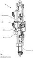
- FIG. 2 shows an embodiment of a top drive 16 with further details.
- the details of the top drive 16 that are important for the further description are a drive unit 24 in the form of an electric motor (drive motor), a transmission housing 26 with a transmission (not visible) therein, which appropriately converts the speed and the torque of the drive unit 24 so that the drill pipe is suitably driven during drilling, and a hydraulic unit 28 which, for example, supplies the operating pressure for the hydraulic movement of so-called elevator brackets 30.
- An oil sump 32 is formed in the interior of a lower section of the transmission housing 26. Parts of the gear oil used for the gearbox are located here.
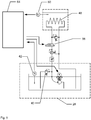
- the representation in Fig. 3 is a schematic simplified representation of the above-mentioned details of a top drive 16 ( Fig. 2 ) in the form of a hydraulic plan.
- the hydraulic unit 28 is shown in the lower area of the illustration.
- the hydraulic unit 28 includes a trough 34 for hydraulic fluid 36, in which hydraulic fluid 36 is located when a top drive 16 is ready or in operation.
- the hydraulic unit 28 also includes a hydraulic pump 38 provided for conveying the hydraulic fluid 36 with a motor for driving it, a pressure limiting valve 40 and a temperature sensor 42.
- the temperature sensor 42 detects a temperature of the hydraulic fluid 36 (hydraulic fluid temperature). Accordingly, this temperature sensor 42 is also referred to as hydraulic fluid temperature sensor 42.
- the hydraulic fluid temperature sensor 42 supplies a hydraulic fluid temperature measured value T1 as a hydraulic fluid temperature or as a measure of the hydraulic fluid temperature.
- Fig. 3 shows in the area of the hydraulic unit 28, by means of the hydraulic unit 28 - specifically by means of the hydraulic pump 38 included therein - the hydraulic fluid 36 can be circulated via the pressure relief valve 40.
- the hydraulic fluid 36 is conveyed out of the tub 34 and discharged into the tub 34 again at the outlet of the pressure limiting valve 40. This results in a circuit of the hydraulic fluid 36.
- This circuit is referred to as a first circuit or, briefly, as a first circuit to distinguish it from a circuit described below.
- the hydraulic fluid 36 is circulated in the first circuit via the pressure limiting valve 40, the hydraulic fluid 36 is heated by means of the power loss generated in the pressure limiting valve 40 (hydraulic heating).
- the pressure relief valve 40 is part of the hydraulic unit 28.
- the hydraulic unit 28 in turn is part of the top drive 16. This justifies the designation of the pressure relief valve 40 and the hydraulic unit 28 as parts of the top drive 16, that is to say as comprised by the top drive 16.
- a transmission oil pan 44 located in the transmission housing 26 of the top drive 16 is shown.
- gear oil 46 in the gear oil pan 44 which - like the hydraulic fluid 36 - is only shown by the surface of an exemplary fluid level.
- a heat exchanger 48 In a lower area of the transmission oil pan 44, i.e. at the level of the oil sump 32 ( Fig. 2 ), there is a heat exchanger 48.
- a temperature sensor 50 In the transmission housing 26 there is also a temperature sensor 50.
- This temperature sensor 50 detects a temperature of the transmission oil (transmission oil temperature) in the area of the oil sump 32. Accordingly, this temperature sensor 50 is also referred to as a transmission oil temperature sensor 50 for distinction.
- the transmission oil temperature sensor 50 supplies a transmission oil temperature measured value T2 as the transmission oil temperature or as a measure of the transmission oil temperature.
- the heat exchanger 48 belongs to a second hydraulic circuit starting from the hydraulic unit 28, the first hydraulic circuit - as described above - being formed within the hydraulic unit 28 and being active when the hydraulic fluid 36 is circulated via the pressure relief valve 40.
- the second hydraulic circuit includes a flow control valve 52, a pressure control valve 54, a directional control valve 56 and a further pressure relief valve 58 provided to protect the heat exchanger 48.
- FIG. 4 shows the partially sectioned gear housing 26, so that a view of the interior thereof and the gear oil pan 44 formed there with the oil sump 32 in a lower region of the gear oil pan 44 is possible.
- the heat exchanger 48 which is shown here in the form of two coils, is arranged in the area of the oil sump 32 in the transmission oil pan 44.
- the two coils are connected to each other so that the above-mentioned second hydraulic circuit comprises the two coils.
- the tube coil or a single tube coil or more than the two tube coils shown can be designed as so-called finned tubes to enlarge the effective surface.
- the hydraulic fluid 36 conveyed by the hydraulic unit 28 flows into the heat exchanger 48 on a supply side 60 and leaves the heat exchanger 48 and thus the transmission housing 26 on a return side 62.
- the representation in Fig. 5 is a partial repetition of the representation in Fig. 3 , To get an overview of the representation in Fig. 5 not to complicate unnecessarily, not all reference numerals are repeated. In this respect, the representation in Fig. 3 directed. Otherwise shows Fig. 5 a schematically simplified control device 64 as an example of means for executing the method described here and below.
- the control device 64 comprises, for example in a manner known per se, a processing unit (not shown) in the form of or in the manner of a microprocessor and a memory (also not shown) into which a control program can be loaded, which is executed by the processing unit when the control device 64 is in operation becomes.
- the functionality implemented in the control program and the functionality of the control device 64 thus defined is briefly as follows:
- the control device 64 detects at least the transmission oil temperature measured value T2 supplied by the transmission oil temperature sensor 50.
- the hydraulic unit 28 for circulating the hydraulic fluid 36 is controlled via the pressure limiting valve 40.
- the transmission oil temperature dependency can be realized in that the transmission oil temperature measured value T2 is compared with a predetermined or predeterminable temperature limit value and in that the hydraulic unit 28 for circulating the hydraulic fluid 36 via the pressure limiting valve 40 is controlled when the transmission oil temperature measured value T2 is below the temperature limit.
- the temperature limit value can be implemented as the content of a memory location of the control device 64.
- the temperature limit can thus be specified, but at the same time can be adapted to the respective conditions, for example the gear oil and its viscosity. For example, a value of minus 20 ° C can be used as the temperature limit.
- control device 64 causes the hydraulic fluid 36 to be passed through the heat exchanger 48 placed in the transmission oil pan 44 as a function of temperature and / or time.
- the directional control valve 56 is activated, which in the Fig. 3 and Fig. 5 Configuration shown in the open state, the second circuit and thus the path for the hydraulic fluid 36 in the heat exchanger 48, the first circuit remains active via the pressure relief valve 40.
- the flow control valve 52 is effective for dividing the volume flow of the hydraulic fluid 36 between the first and the second circuit.
- the measurement of the measured values described so far by the control device 64 and the control of individual units effected by the control device 64 is shown in the illustration in FIG Fig. 5 indicated by arrows.
- the effective paths shown in this way are implemented in practice in the form of line connections, via which measured values can be recorded and control signals can be transmitted.
- the control device 64 realizes a time-dependent introduction of the hydraulic fluid 36 into the heat exchanger 48, the control device 64 comprises a timer which is started when the hydraulic fluid 36 begins to circulate via the pressure relief valve 40 and which generates a signal on the basis of which the Control device 64 generates the signal for actuating the directional control valve 56 for releasing the second circuit for the hydraulic fluid 36.
- the timer can be implemented in a manner known per se as a decrementing or incrementing counter.
- the start or target value of such a counter can be specified as the content of a memory location of the control device 64.
- the value used in each case is therefore an empirical value that can be adapted to the respective circumstances.
- the control device 64 manages a plurality of such values, from which a user can use the hydraulic fluid 36 used, the delivery rate of the hydraulic unit 28, for example twenty liters per minute, and the pressure to which the Pressure relief valve 40 the pressure of the hydraulic fluid 36 limited / reduced, for example 210 bar, a value suitable for the current situation is selected.
- the values managed by the control device 64 can then be organized in a multidimensional matrix, for example, and a suitable time value is selected by specifying or selecting the individual parameters. In this way, it can be achieved that a measurement of the hydraulic fluid temperature is not required, and accordingly a hydraulic fluid temperature sensor 42, which is otherwise provided for measuring the hydraulic fluid temperature, can be saved.
- the control device 64 detects the hydraulic fluid temperature measured value T1 supplied by the hydraulic fluid temperature sensor 42 at least during the circulation of the hydraulic fluid 36 via the pressure limiting valve 40 and compares it with a predetermined or predeterminable temperature threshold value.
- the temperature threshold is implemented in particular as the content of a memory location of the control device 64.
- the temperature threshold value can thus be predetermined, but at the same time it can be adapted to the respective conditions, for example the quantity ratios of hydraulic fluid 36 and gear oil 46 and / or a measure for the heat transfer at the heat exchanger 48 to the gear oil 46.
- a value of +40 ° C can be used as the temperature threshold.
- the control device 64 controls the directional control valve 56, as described above.
- This type of hydraulic transmission oil heating remains active until at least a predetermined minimum operating temperature of the transmission oil 46 is reached.
- the control device 64 monitors the transmission oil temperature measured value T2 continuously or at regular intervals after the initial activation of the circulation of the hydraulic fluid 36 via the pressure limiting valve 40. As soon as the transmission oil temperature measured value T2 reaches or exceeds the specified minimum operating temperature of the transmission oil 46, the hydraulic transmission oil heating can be deactivated.
- the hydraulic transmission oil heater is automatically reactivated under control of the control device 64 when the transmission oil temperature measured value T2 is below the predetermined minimum operating temperature of the transmission oil 46 falls, or at the latest when the transmission oil temperature measured value T2 falls below the minimum temperature.
- the hydraulic transmission oil heating that is to say the method for the operation of the top drive 16 described here, can be started automatically by the control device 64 continuously monitoring the transmission oil temperature measured value T2 and activating the hydraulic transmission oil heating when the temperature falls below the minimum operating temperature or at least falls below the minimum temperature.
- the hydraulic transmission oil heating can also be activated by only evaluating the transmission oil temperature measured value T2 in the manner described above in connection with a manual or automatic activation of the top drive 16 and activating the hydraulic transmission oil heating if necessary.
- the activation of the top drive 16 is then delayed or prevented by the control device 64 until at least the minimum operating temperature is reached due to the hydraulic transmission oil heating for the transmission oil 46.
- the transmission oil 46 can also be heated using other heat sources.
- the transmission oil 46 and / or the hydraulic fluid 36 can then serve as a sink for heat generated in other locations.
- a switchable heat exchanger or a separate heat exchanger can be provided in the transmission oil pan 44 and / or in the pan 34 for the hydraulic fluid 36, into which, for example, hot steam for cooling an external heat source is introduced.
- a so-called top drive 16 is specified as a device for driving drill rods and a method for its operation, in which means are provided for heating the gear oil 46 used by the top drive 16 , which can also be fed by means of an emergency power unit and comprise a hydraulic unit 28 and a pressure limiting valve 40 of the top drive 16, hydraulic fluid 36 being circulated via the pressure limiting valve 40 by means of the hydraulic unit 28 to heat the transmission oil 46, and the thermal energy thus generated via one of the hydraulic fluid 36 flows through the heat exchanger 48 to the transmission oil 46.
Landscapes
- Engineering & Computer Science (AREA)
- Mining & Mineral Resources (AREA)
- Life Sciences & Earth Sciences (AREA)
- Geology (AREA)
- Mechanical Engineering (AREA)
- General Engineering & Computer Science (AREA)
- Fluid Mechanics (AREA)
- Environmental & Geological Engineering (AREA)
- Physics & Mathematics (AREA)
- General Life Sciences & Earth Sciences (AREA)
- Geochemistry & Mineralogy (AREA)
- Fluid-Pressure Circuits (AREA)
- General Details Of Gearings (AREA)
- Earth Drilling (AREA)
- Drilling And Boring (AREA)
Claims (10)
- Dispositif d'entraînement destiné à entraîner une tige de forage lors de la réalisation de forages dans des gisements d'hydrocarbures sous la forme d'un topdrive (16),
dans lequel le topdrive (16) comprend un agrégat hydraulique (28) avec une cuve (34) pour fluide hydraulique (36), dans laquelle se trouve du fluide hydraulique (36) avec le topdrive prêt à fonctionner (16),
dans lequel le topdrive (16) comprend une transmission avec un carter d'huile de transmission (44),
dans lequel se trouve de l'huile de transmission (46) avec le topdrive prêt à fonctionner (16),
dans lequel, au moyen d'un capteur de température de l'huile de transmission (50), une valeur de mesure de la température de l'huile de transmission (T2) peut être mesurée pour connaître une température de l'huile de transmission (46) dans le carter de l'huile de transmission (44),
dans lequel, au moyen de l'agrégat hydraulique (28), le fluide hydraulique (36) peut circuler en fonction de la valeur de mesure de la température de l'huile de transmission (T2) à travers une vanne de limitation de pression (40) comprise dans le topdrive (16), de sorte qu'une perte de puissance générée par le passage à travers la vanne de limitation de pression (40) conduit au réchauffement du fluide hydraulique (36), et
dans lequel, au moyen de l'agrégat hydraulique (28), le fluide hydraulique (36) peut être guidé à travers un échangeur de chaleur (48) placé dans le carter d'huile de transmission (44) en fonction de la température du fluide hydraulique et/ou en fonction du temps. - Dispositif d'entraînement selon la revendication 1,
dans lequel, au moyen d'un capteur de température du fluide hydraulique (42), une valeur de mesure de la température du fluide hydraulique (T1) peut être mesurée pour connaître une température du fluide hydraulique (36) dans la cuve (34) de l'agrégat hydraulique (28) et
dans lequel, au moyen de l'agrégat hydraulique (28), le fluide hydraulique (36) peut être guidé à travers l'échangeur de chaleur (48) placé dans le carter d'huile de transmission (44) en fonction de la valeur de mesure de la température du fluide hydraulique (T1). - Dispositif d'entraînement selon la revendication 1 ou 2,
dans lequel une soupape de réglage de flux (52) est agencée entre l'agrégat hydraulique (28) et l'échangeur de chaleur (48). - Dispositif d'entraînement selon la revendication 1, 2 ou 3,
dans lequel une vanne directionnelle (56) est agencée entre l'agrégat hydraulique (28) et l'échangeur de chaleur (48). - Dispositif d'entraînement selon l'une des revendications précédentes avec un échangeur de chaleur (48) sous la forme d'un tube à ailettes.
- Procédé permettant de faire fonctionner un dispositif d'entraînement déterminé pour entraîner une tige de forage lors de la réalisation de forages dans des gisements d'hydrocarbures sous la forme d'un topdrive (16) selon l'une des revendications 1 à 5,
dans lequel l'agrégat hydraulique (28) est commandé par l'intermédiaire de la vanne de limitation de pression (40) pour la circulation du fluide hydraulique (36) en fonction de la valeur de mesure de la température de l'huile de transmission (T2) et
dans lequel le fluide hydraulique (36) est guidé à travers l'échangeur de chaleur (48) placé dans le carter d'huile de transmission (44) en fonction de la température et/ou du temps. - Procédé selon la revendication 6,
dans lequel, à une valeur de mesure de la température de l'huile de transmission (T2), l'agrégat hydraulique (28) est commandé par l'intermédiaire de la vanne de limitation de pression (40) pour la circulation du fluide hydraulique (36) au-dessous d'une valeur limite de température prédéterminée ou qui peut être prédéterminée. - Procédé selon la revendication 6 ou 7 pour faire fonctionner un dispositif d'entraînement selon la revendication 2 ou selon l'une des revendications 3 à 5, quand chacune des revendications 3 à 5 dépend de la revendication 2,
dans lequel, au moyen du capteur de température du fluide hydraulique (42) une valeur de mesure de la température du fluide hydraulique (T1) est détectée pour connaître une température du fluide hydraulique (36) dans la cuve (34) de l'agrégat hydraulique (28) et
dans lequel, à une valeur de mesure de la température du fluide hydraulique (T1), le fluide hydraulique (36) est guidé à travers l'échangeur de chaleur (48) placé dans le carter d'huile de transmission (44) au-dessus d'une valeur seuil de température prédéterminée ou qui peut être prédéterminée. - Procédé selon la revendication 6, 7 ou 8 pour faire fonctionner un dispositif d'entraînement selon la revendication 4 ou selon la revendication 5, quand celle-ci dépend de la revendication 4,
dans lequel la vanne directionnelle (56) agencée entre l'agrégat hydraulique (28) et l'échangeur de chaleur (48) est agencé en amont de la vanne de limitation de pression (40) et
dans lequel le flux de fluide hydraulique est permuté par une commande de la vanne directionnelle (56) entre une première voie par la vanne de limitation de pression (40) et une deuxième voie par l'échangeur de chaleur (48). - Procédé selon la revendication 6, 7 ou 8 pour faire fonctionner un dispositif d'entraînement selon la revendication 4 ou selon la revendication 5, quand celle-ci dépend de la revendication 4,
dans lequel la vanne directionnelle (56) agencée entre l'agrégat hydraulique (28) et l'échangeur de chaleur (48) est agencée en aval de la vanne de limitation de pression (40) et
dans lequel le flux de fluide hydraulique est permuté par une commande de la vanne directionnelle (56) entre une première voie par la vanne de limitation de pression (40) et une deuxième voie par la vanne de limitation de pression (40) et par l'échangeur de chaleur (48).
Priority Applications (1)
| Application Number | Priority Date | Filing Date | Title |
|---|---|---|---|
| PL14707744T PL2880240T3 (pl) | 2013-03-05 | 2014-03-03 | Urządzenie napędowe do napędzania żerdzi wiertniczej oraz sposób sterowania działaniem takiego urządzenia napędowego |
Applications Claiming Priority (2)
| Application Number | Priority Date | Filing Date | Title |
|---|---|---|---|
| DE102013203756.2A DE102013203756A1 (de) | 2013-03-05 | 2013-03-05 | Antriebsvorrichtung zum Antrieb von Bohrgestänge und Verfahren zum Betrieb einer solchen Antriebsvorrichtung |
| PCT/EP2014/054020 WO2014135475A2 (fr) | 2013-03-05 | 2014-03-03 | Dispositif d'entraînement destiné à entraîner un train de tiges et procédé permettant de faire fonctionner un tel dispositif d'entraînement |
Publications (2)
| Publication Number | Publication Date |
|---|---|
| EP2880240A2 EP2880240A2 (fr) | 2015-06-10 |
| EP2880240B1 true EP2880240B1 (fr) | 2020-03-04 |
Family
ID=50193487
Family Applications (1)
| Application Number | Title | Priority Date | Filing Date |
|---|---|---|---|
| EP14707744.0A Active EP2880240B1 (fr) | 2013-03-05 | 2014-03-03 | Dispositif d'entraînement destiné à entraîner un train de tiges et procédé permettant de faire fonctionner un tel dispositif d'entraînement |
Country Status (6)
| Country | Link |
|---|---|
| US (1) | US20160010392A1 (fr) |
| EP (1) | EP2880240B1 (fr) |
| DE (1) | DE102013203756A1 (fr) |
| EA (1) | EA029121B1 (fr) |
| PL (1) | PL2880240T3 (fr) |
| WO (1) | WO2014135475A2 (fr) |
Families Citing this family (4)
| Publication number | Priority date | Publication date | Assignee | Title |
|---|---|---|---|---|
| CN107448139A (zh) * | 2017-07-28 | 2017-12-08 | 四川宏华石油设备有限公司 | 一种顶部驱动装置 |
| CN110230464B (zh) * | 2019-05-30 | 2024-06-04 | 北京石油机械有限公司 | 一种基于相变散热的顶驱装置 |
| CN110905398B (zh) * | 2019-12-06 | 2020-09-08 | 中国地质大学(北京) | 一种煤层气开采用抽采口钻设装置 |
| CN113090248B (zh) * | 2019-12-23 | 2023-03-14 | 中联重科股份有限公司 | 旋挖钻机的控制方法、装置及旋挖钻机 |
Family Cites Families (12)
| Publication number | Priority date | Publication date | Assignee | Title |
|---|---|---|---|---|
| US4844162A (en) * | 1987-12-30 | 1989-07-04 | Union Oil Company Of California | Apparatus and method for treating geothermal steam which contains hydrogen sulfide |
| DE3904654A1 (de) * | 1989-02-16 | 1990-08-23 | Laengerer & Reich Kuehler | Waermeaustauscher, insbesondere oelkuehler |
| NL9401191A (nl) * | 1994-07-20 | 1996-03-01 | Applied Power Inc | Hydraulische schakeling. |
| US6217758B1 (en) * | 1999-08-06 | 2001-04-17 | Dana Corporation | Oil sump arrangement with integral filter and heat exchanger |
| US7320374B2 (en) * | 2004-06-07 | 2008-01-22 | Varco I/P, Inc. | Wellbore top drive systems |
| GB2420175B (en) * | 2004-11-10 | 2009-10-28 | Agco Gmbh & Co | Cooling system for farming tractors |
| JP2007085457A (ja) * | 2005-09-22 | 2007-04-05 | Nissan Motor Co Ltd | トランスミッションのオイル温度調整装置 |
| DE102008030969A1 (de) * | 2008-06-30 | 2009-12-31 | Agco Gmbh | Durchflusssteuerung |
| GB2463311B (en) * | 2008-09-09 | 2012-08-08 | Denso Marston Ltd | Cooling system for a vehicle subsystem and a vehicle incorporating such a system |
| DE102009039022A1 (de) * | 2009-08-28 | 2011-03-03 | Bentec Gmbh Drilling & Oilfield Systems | Handhabungsgerät für Bohrgestänge, insbesondere so genannter Pipehandler oder so genannter Topdrive mit Pipehandler, und Betriebsverfahren dafür |
| DE102011008672A1 (de) * | 2011-01-15 | 2012-07-19 | Hydac Filtertechnik Gmbh | Vorrichtung zum Schmieren eines Getriebes sowie eines Lagers |
| DE102013213506B4 (de) * | 2012-10-15 | 2023-06-15 | Vitesco Technologies GmbH | Verfahren zum Betreiben eines Kraftstoffeinspritzsystems mit einer Kraftstofffilterheizung und Kraftstoffeinspritzsystem |
-
2013
- 2013-03-05 DE DE102013203756.2A patent/DE102013203756A1/de not_active Withdrawn
-
2014
- 2014-03-03 EP EP14707744.0A patent/EP2880240B1/fr active Active
- 2014-03-03 US US14/772,367 patent/US20160010392A1/en not_active Abandoned
- 2014-03-03 WO PCT/EP2014/054020 patent/WO2014135475A2/fr not_active Ceased
- 2014-03-03 EA EA201591619A patent/EA029121B1/ru not_active IP Right Cessation
- 2014-03-03 PL PL14707744T patent/PL2880240T3/pl unknown
Non-Patent Citations (1)
| Title |
|---|
| None * |
Also Published As
| Publication number | Publication date |
|---|---|
| EA029121B1 (ru) | 2018-02-28 |
| EP2880240A2 (fr) | 2015-06-10 |
| EA201591619A1 (ru) | 2016-01-29 |
| DE102013203756A1 (de) | 2014-09-11 |
| PL2880240T3 (pl) | 2020-09-21 |
| WO2014135475A2 (fr) | 2014-09-12 |
| WO2014135475A3 (fr) | 2014-12-31 |
| US20160010392A1 (en) | 2016-01-14 |
Similar Documents
| Publication | Publication Date | Title |
|---|---|---|
| DE102011116394B4 (de) | Steuerung und Diagnose eines Verschlusses einer Kühlergrillöffnung über bidirektionale Kommunikation unter Verwendung eines Einzeldrahtes | |
| EP2880240B1 (fr) | Dispositif d'entraînement destiné à entraîner un train de tiges et procédé permettant de faire fonctionner un tel dispositif d'entraînement | |
| DE102015006308B4 (de) | Ladevorrichtung zum induktiven Laden eines elektrischen Energiespeichers eines Kraftfahrzeugs und Verfahren zum Betreiben einer Ladevorrichtung | |
| DE3246838A1 (de) | Lufttemperatur-regelvorrichtung | |
| EP2913594B1 (fr) | Procédé de fonctionnement d'une installation de chauffage sans ballon tampon, en particulier destiné à garantir un fonctionnement fiable et correct | |
| DE102013221584A1 (de) | Vorrichtung zur Versorgung eines Getriebes, Getriebevorrichtung und Verfahren zur Versorgung eines Getriebes | |
| DE102012107016B4 (de) | Verfahren zum Betreiben einer Heizung für eine Batterie eines zumindest teil- und/oder zeitweise elektrisch angetriebenen Kraftfahrzeugs | |
| DE102006025053A1 (de) | Verfahren zur Steuerung einer Brennkraftmaschine | |
| DE102012008436A1 (de) | Verfahren zum Steuern einer hydrodynamischen Kupplung | |
| WO2007048394A1 (fr) | Dispositif de commande d'un appareil de chauffage independant du moteur, systeme de chauffage et procede de commande d'un appareil de chauffage independant du moteur | |
| EP2464886B1 (fr) | Procédé de commande de l'apport en agent de refroidissement et de l'apport en lubrifiant à l'embrayage d'un véhicule à moteur comprenant une boîte de vitesses automatique | |
| EP3180503B1 (fr) | Procédé pour faire fonctionner un circuit de fluide d'un véhicule automobile et circuit de fluide correspondant | |
| DE2813081B1 (de) | Anordnung zur Beeinflussung der Temperatur mindestens eines Raumes eines Gebaeudes | |
| DE4036134A1 (de) | Verfahren und einrichtung zur ueberwachung der temperatur von widerstaenden | |
| DE3030565A1 (de) | Heizkessel fuer heizungsanlagen | |
| DE102015119450B4 (de) | Vorrichtung und Verfahren zum Bestimmen einer Porenverstopfung in einem Maschinenkühlsystem | |
| DE19711682A1 (de) | Heizgerät für ein Fahrzeug | |
| EP3002871A1 (fr) | Procédé d'initialisation d'une surveillance de température, procédé de commande pour un moteur électrique et commande électrique de moteur | |
| EP2827082B1 (fr) | Procédé de commande d'un compresseur d'une pompe à chaleur | |
| DE202014103748U1 (de) | Umwälzpumpe für eine Heizungsanlage | |
| DE102010053209A1 (de) | Heizungssystem und Verfahren zum Heizen einer Mehrzahl von Räumen | |
| DE10138821B4 (de) | Verfahren zum Ermitteln einer Heizluft-Ausblastemperatur eines Luftheizgerätes | |
| DE102014216659B4 (de) | Verfahren und Managementsystem zum Betrieb eines Kühlsystems einer Verbrennungskraftmaschine | |
| DE102023129436B3 (de) | Verfahren zum sicheren Betrieb eines Kombinationsgargeräts sowie Kombinationsgargerät | |
| DE10227163B4 (de) | Verfahren zum Ermitteln eines Kriteriums zur Veränderung eines Istwertes aus einer Mehrzahl aufeinander folgend erhaltener Messwerte und Heizgerät mit einer zur Durchführung des Verfahrens ausgebildeten Ansteuervorrichtung |
Legal Events
| Date | Code | Title | Description |
|---|---|---|---|
| PUAI | Public reference made under article 153(3) epc to a published international application that has entered the european phase |
Free format text: ORIGINAL CODE: 0009012 |
|
| 17P | Request for examination filed |
Effective date: 20150306 |
|
| AK | Designated contracting states |
Kind code of ref document: A2 Designated state(s): AL AT BE BG CH CY CZ DE DK EE ES FI FR GB GR HR HU IE IS IT LI LT LU LV MC MK MT NL NO PL PT RO RS SE SI SK SM TR |
|
| AX | Request for extension of the european patent |
Extension state: BA ME |
|
| DAX | Request for extension of the european patent (deleted) | ||
| STAA | Information on the status of an ep patent application or granted ep patent |
Free format text: STATUS: EXAMINATION IS IN PROGRESS |
|
| 17Q | First examination report despatched |
Effective date: 20180322 |
|
| GRAP | Despatch of communication of intention to grant a patent |
Free format text: ORIGINAL CODE: EPIDOSNIGR1 |
|
| STAA | Information on the status of an ep patent application or granted ep patent |
Free format text: STATUS: GRANT OF PATENT IS INTENDED |
|
| INTG | Intention to grant announced |
Effective date: 20191129 |
|
| GRAS | Grant fee paid |
Free format text: ORIGINAL CODE: EPIDOSNIGR3 |
|
| GRAA | (expected) grant |
Free format text: ORIGINAL CODE: 0009210 |
|
| STAA | Information on the status of an ep patent application or granted ep patent |
Free format text: STATUS: THE PATENT HAS BEEN GRANTED |
|
| AK | Designated contracting states |
Kind code of ref document: B1 Designated state(s): AL AT BE BG CH CY CZ DE DK EE ES FI FR GB GR HR HU IE IS IT LI LT LU LV MC MK MT NL NO PL PT RO RS SE SI SK SM TR |
|
| REG | Reference to a national code |
Ref country code: GB Ref legal event code: FG4D Free format text: NOT ENGLISH |
|
| REG | Reference to a national code |
Ref country code: CH Ref legal event code: EP |
|
| REG | Reference to a national code |
Ref country code: AT Ref legal event code: REF Ref document number: 1240553 Country of ref document: AT Kind code of ref document: T Effective date: 20200315 |
|
| REG | Reference to a national code |
Ref country code: DE Ref legal event code: R096 Ref document number: 502014013740 Country of ref document: DE |
|
| REG | Reference to a national code |
Ref country code: IE Ref legal event code: FG4D Free format text: LANGUAGE OF EP DOCUMENT: GERMAN |
|
| REG | Reference to a national code |
Ref country code: NL Ref legal event code: FP |
|
| REG | Reference to a national code |
Ref country code: NO Ref legal event code: T2 Effective date: 20200304 |
|
| PG25 | Lapsed in a contracting state [announced via postgrant information from national office to epo] |
Ref country code: RS Free format text: LAPSE BECAUSE OF FAILURE TO SUBMIT A TRANSLATION OF THE DESCRIPTION OR TO PAY THE FEE WITHIN THE PRESCRIBED TIME-LIMIT Effective date: 20200304 Ref country code: FI Free format text: LAPSE BECAUSE OF FAILURE TO SUBMIT A TRANSLATION OF THE DESCRIPTION OR TO PAY THE FEE WITHIN THE PRESCRIBED TIME-LIMIT Effective date: 20200304 |
|
| PG25 | Lapsed in a contracting state [announced via postgrant information from national office to epo] |
Ref country code: SE Free format text: LAPSE BECAUSE OF FAILURE TO SUBMIT A TRANSLATION OF THE DESCRIPTION OR TO PAY THE FEE WITHIN THE PRESCRIBED TIME-LIMIT Effective date: 20200304 Ref country code: LV Free format text: LAPSE BECAUSE OF FAILURE TO SUBMIT A TRANSLATION OF THE DESCRIPTION OR TO PAY THE FEE WITHIN THE PRESCRIBED TIME-LIMIT Effective date: 20200304 Ref country code: GR Free format text: LAPSE BECAUSE OF FAILURE TO SUBMIT A TRANSLATION OF THE DESCRIPTION OR TO PAY THE FEE WITHIN THE PRESCRIBED TIME-LIMIT Effective date: 20200605 Ref country code: HR Free format text: LAPSE BECAUSE OF FAILURE TO SUBMIT A TRANSLATION OF THE DESCRIPTION OR TO PAY THE FEE WITHIN THE PRESCRIBED TIME-LIMIT Effective date: 20200304 Ref country code: BG Free format text: LAPSE BECAUSE OF FAILURE TO SUBMIT A TRANSLATION OF THE DESCRIPTION OR TO PAY THE FEE WITHIN THE PRESCRIBED TIME-LIMIT Effective date: 20200604 |
|
| REG | Reference to a national code |
Ref country code: LT Ref legal event code: MG4D |
|
| PG25 | Lapsed in a contracting state [announced via postgrant information from national office to epo] |
Ref country code: RO Free format text: LAPSE BECAUSE OF FAILURE TO SUBMIT A TRANSLATION OF THE DESCRIPTION OR TO PAY THE FEE WITHIN THE PRESCRIBED TIME-LIMIT Effective date: 20200304 Ref country code: SK Free format text: LAPSE BECAUSE OF FAILURE TO SUBMIT A TRANSLATION OF THE DESCRIPTION OR TO PAY THE FEE WITHIN THE PRESCRIBED TIME-LIMIT Effective date: 20200304 Ref country code: IS Free format text: LAPSE BECAUSE OF FAILURE TO SUBMIT A TRANSLATION OF THE DESCRIPTION OR TO PAY THE FEE WITHIN THE PRESCRIBED TIME-LIMIT Effective date: 20200704 Ref country code: SM Free format text: LAPSE BECAUSE OF FAILURE TO SUBMIT A TRANSLATION OF THE DESCRIPTION OR TO PAY THE FEE WITHIN THE PRESCRIBED TIME-LIMIT Effective date: 20200304 Ref country code: EE Free format text: LAPSE BECAUSE OF FAILURE TO SUBMIT A TRANSLATION OF THE DESCRIPTION OR TO PAY THE FEE WITHIN THE PRESCRIBED TIME-LIMIT Effective date: 20200304 Ref country code: LT Free format text: LAPSE BECAUSE OF FAILURE TO SUBMIT A TRANSLATION OF THE DESCRIPTION OR TO PAY THE FEE WITHIN THE PRESCRIBED TIME-LIMIT Effective date: 20200304 Ref country code: ES Free format text: LAPSE BECAUSE OF FAILURE TO SUBMIT A TRANSLATION OF THE DESCRIPTION OR TO PAY THE FEE WITHIN THE PRESCRIBED TIME-LIMIT Effective date: 20200304 Ref country code: CZ Free format text: LAPSE BECAUSE OF FAILURE TO SUBMIT A TRANSLATION OF THE DESCRIPTION OR TO PAY THE FEE WITHIN THE PRESCRIBED TIME-LIMIT Effective date: 20200304 Ref country code: PT Free format text: LAPSE BECAUSE OF FAILURE TO SUBMIT A TRANSLATION OF THE DESCRIPTION OR TO PAY THE FEE WITHIN THE PRESCRIBED TIME-LIMIT Effective date: 20200729 |
|
| REG | Reference to a national code |
Ref country code: DE Ref legal event code: R097 Ref document number: 502014013740 Country of ref document: DE |
|
| PLBE | No opposition filed within time limit |
Free format text: ORIGINAL CODE: 0009261 |
|
| STAA | Information on the status of an ep patent application or granted ep patent |
Free format text: STATUS: NO OPPOSITION FILED WITHIN TIME LIMIT |
|
| PG25 | Lapsed in a contracting state [announced via postgrant information from national office to epo] |
Ref country code: DK Free format text: LAPSE BECAUSE OF FAILURE TO SUBMIT A TRANSLATION OF THE DESCRIPTION OR TO PAY THE FEE WITHIN THE PRESCRIBED TIME-LIMIT Effective date: 20200304 |
|
| 26N | No opposition filed |
Effective date: 20201207 |
|
| PG25 | Lapsed in a contracting state [announced via postgrant information from national office to epo] |
Ref country code: SI Free format text: LAPSE BECAUSE OF FAILURE TO SUBMIT A TRANSLATION OF THE DESCRIPTION OR TO PAY THE FEE WITHIN THE PRESCRIBED TIME-LIMIT Effective date: 20200304 |
|
| PG25 | Lapsed in a contracting state [announced via postgrant information from national office to epo] |
Ref country code: MC Free format text: LAPSE BECAUSE OF FAILURE TO SUBMIT A TRANSLATION OF THE DESCRIPTION OR TO PAY THE FEE WITHIN THE PRESCRIBED TIME-LIMIT Effective date: 20200304 |
|
| REG | Reference to a national code |
Ref country code: CH Ref legal event code: PL |
|
| REG | Reference to a national code |
Ref country code: BE Ref legal event code: MM Effective date: 20210331 |
|
| PG25 | Lapsed in a contracting state [announced via postgrant information from national office to epo] |
Ref country code: CH Free format text: LAPSE BECAUSE OF NON-PAYMENT OF DUE FEES Effective date: 20210331 Ref country code: LI Free format text: LAPSE BECAUSE OF NON-PAYMENT OF DUE FEES Effective date: 20210331 Ref country code: LU Free format text: LAPSE BECAUSE OF NON-PAYMENT OF DUE FEES Effective date: 20210303 Ref country code: IE Free format text: LAPSE BECAUSE OF NON-PAYMENT OF DUE FEES Effective date: 20210303 Ref country code: FR Free format text: LAPSE BECAUSE OF NON-PAYMENT OF DUE FEES Effective date: 20210331 |
|
| PG25 | Lapsed in a contracting state [announced via postgrant information from national office to epo] |
Ref country code: BE Free format text: LAPSE BECAUSE OF NON-PAYMENT OF DUE FEES Effective date: 20210331 |
|
| PG25 | Lapsed in a contracting state [announced via postgrant information from national office to epo] |
Ref country code: HU Free format text: LAPSE BECAUSE OF FAILURE TO SUBMIT A TRANSLATION OF THE DESCRIPTION OR TO PAY THE FEE WITHIN THE PRESCRIBED TIME-LIMIT; INVALID AB INITIO Effective date: 20140303 |
|
| PG25 | Lapsed in a contracting state [announced via postgrant information from national office to epo] |
Ref country code: CY Free format text: LAPSE BECAUSE OF FAILURE TO SUBMIT A TRANSLATION OF THE DESCRIPTION OR TO PAY THE FEE WITHIN THE PRESCRIBED TIME-LIMIT Effective date: 20200304 |
|
| PG25 | Lapsed in a contracting state [announced via postgrant information from national office to epo] |
Ref country code: MK Free format text: LAPSE BECAUSE OF FAILURE TO SUBMIT A TRANSLATION OF THE DESCRIPTION OR TO PAY THE FEE WITHIN THE PRESCRIBED TIME-LIMIT Effective date: 20200304 |
|
| PG25 | Lapsed in a contracting state [announced via postgrant information from national office to epo] |
Ref country code: MT Free format text: LAPSE BECAUSE OF FAILURE TO SUBMIT A TRANSLATION OF THE DESCRIPTION OR TO PAY THE FEE WITHIN THE PRESCRIBED TIME-LIMIT Effective date: 20200304 |
|
| PG25 | Lapsed in a contracting state [announced via postgrant information from national office to epo] |
Ref country code: TR Free format text: LAPSE BECAUSE OF FAILURE TO SUBMIT A TRANSLATION OF THE DESCRIPTION OR TO PAY THE FEE WITHIN THE PRESCRIBED TIME-LIMIT Effective date: 20200304 |
|
| PGFP | Annual fee paid to national office [announced via postgrant information from national office to epo] |
Ref country code: GB Payment date: 20260304 Year of fee payment: 13 |
|
| PGFP | Annual fee paid to national office [announced via postgrant information from national office to epo] |
Ref country code: NO Payment date: 20260318 Year of fee payment: 13 Ref country code: DE Payment date: 20260218 Year of fee payment: 13 |
|
| PGFP | Annual fee paid to national office [announced via postgrant information from national office to epo] |
Ref country code: AT Payment date: 20260318 Year of fee payment: 13 |
|
| PGFP | Annual fee paid to national office [announced via postgrant information from national office to epo] |
Ref country code: IT Payment date: 20260320 Year of fee payment: 13 |
|
| PGFP | Annual fee paid to national office [announced via postgrant information from national office to epo] |
Ref country code: NL Payment date: 20260323 Year of fee payment: 13 |
|
| PGFP | Annual fee paid to national office [announced via postgrant information from national office to epo] |
Ref country code: PL Payment date: 20260210 Year of fee payment: 13 |