EP2880246B1 - Trépan avec application de force utilisant un moteur et un mécanisme à vis pour commander l'extension d'un patin dans le trépan - Google Patents
Trépan avec application de force utilisant un moteur et un mécanisme à vis pour commander l'extension d'un patin dans le trépan Download PDFInfo
- Publication number
- EP2880246B1 EP2880246B1 EP13825665.6A EP13825665A EP2880246B1 EP 2880246 B1 EP2880246 B1 EP 2880246B1 EP 13825665 A EP13825665 A EP 13825665A EP 2880246 B1 EP2880246 B1 EP 2880246B1
- Authority
- EP
- European Patent Office
- Prior art keywords
- drill bit
- pad
- drive
- force application
- application device
- Prior art date
- Legal status (The legal status is an assumption and is not a legal conclusion. Google has not performed a legal analysis and makes no representation as to the accuracy of the status listed.)
- Active
Links
Images


Classifications
-
- E—FIXED CONSTRUCTIONS
- E21—EARTH OR ROCK DRILLING; MINING
- E21B—EARTH OR ROCK DRILLING; OBTAINING OIL, GAS, WATER, SOLUBLE OR MELTABLE MATERIALS OR A SLURRY OF MINERALS FROM WELLS
- E21B10/00—Drill bits
- E21B10/62—Drill bits characterised by parts, e.g. cutting elements, which are detachable or adjustable
Definitions
- This disclosure relates generally to drill bits and systems that utilize same for drilling wellbores.
- Oil wells are drilled with a drill string that includes a tubular member having a drilling assembly (also referred to as the "bottomhole assembly” or “BHA”).
- BHA typically includes devices and sensors that provide information relating to a variety of parameters relating to the drilling operations (“drilling parameters”), behavior of the BHA (“BHA parameters”) and parameters relating to the formation surrounding the wellbore (“formation parameters”).
- a drill bit attached to the bottom end of the BHA is rotated by rotating the drill string and/or by a drilling motor (also referred to as a "mud motor”) in the BHA to disintegrate the rock formation to drill the wellbore.
- a drilling motor also referred to as a "mud motor”
- a large number of wellbores are drilled along contoured trajectories.
- a single wellbore may include one or more vertical sections, deviated sections and horizontal sections through differing types of rock formations.
- the rate of penetration (ROP) of the drill changes and can cause (decreases or increases) excessive fluctuations or vibration (lateral or torsional) in the drill bit.
- the ROP is typically controlled by controlling the weight-on-bit (WOB) and rotational speed (revolutions per minute or "RPM”) of the drill bit so as to control drill bit fluctuations.
- WB weight-on-bit
- RPM rotational speed
- the WOB is controlled by controlling the hook load at the surface and the RPM is controlled by controlling the drill string rotation at the surface and/or by controlling the drilling motor speed in the BHA.
- Controlling the drill bit fluctuations and ROP by such methods requires the drilling system or operator to take actions at the surface. The impact of such surface actions on the drill bit fluctuations is not substantially immediate.
- Drill bit aggressiveness contributes to the vibration, oscillation and the drill bit for a given WOB and drill bit rotational speed.
- Depth of cut of the drill bit is a contributing factor relating to the drill bit aggressiveness. Controlling the depth of cut can provide smoother borehole, avoid premature damage to the cutters and longer operating life of the drill bit.
- US2010/0071956 discloses a drill bit including an extendable pad.
- US2010/0212966 discloses a downhole tool including a gear set that may transfer torque from a turbine to a linear screw member.
- the disclosure herein provides a drill bit and drilling systems using the same configured to control the aggressiveness of a drill bit during drilling of a wellbore.
- the present invention provides a drill bit as claimed in claim 1.
- the present invention also provides a method of making a drill bit as claimed in claim 14.
- a drill bit in one embodiment includes a pad configured to extend and retract from a surface of the drill bit, and a force application device configured to extend and retract the pad, wherein the force application device includes a screw driven by an electric motor that linearly moves a drive unit to extend and retract the pad from the drill bit surface.
- a method of drilling a wellbore includes: conveying a drill string having a drill bit at an end thereof, wherein the drill bit includes a pad configured to extend and retract from a surface of the drill bit and a force application device configured to extend and retract the pad, wherein the force application device includes a screw driven by an electric motor that moves a drive unit to extend the pad from the drill bit face; and rotating the drill bit to drill the wellbore.
- FIG. 1 is a schematic diagram of an exemplary drilling system 100 that includes a drill string 120 having a drilling assembly or a bottomhole assembly 190 attached to its bottom end.
- Drill string 120 is shown conveyed in a borehole 126 formed in a formation 195.
- the drilling system 100 includes a conventional derrick 111 erected on a platform or floor 112 that supports a rotary table 114 that is rotated by a prime mover, such as an electric motor (not shown), at a desired rotational speed.
- a drill bit 150 attached to the drilling assembly 190, disintegrates the geological formation 195.
- the drill string 120 is coupled to a draw works 130 via a Kelly joint 121, swivel 128 and line 129 through a pulley.
- Draw works 130 is operated to control the weight on bit ("WOB").
- the drill string 120 may be rotated by a top drive 114a rather than the prime mover and the rotary table 114.
- a suitable drilling fluid 131 (also referred to as the "mud") from a source 132 thereof, such as a mud pit, is circulated under pressure through the drill string 120 by a mud pump 134.
- the drilling fluid 131 passes from the mud pump 134 into the drill string 120 via a desurger 136 and the fluid line 138.
- the drilling fluid 131a discharges at the borehole bottom 151 through openings in the drill bit 150.
- the returning drilling fluid 131b circulates uphole through the annular space or annulus 127 between the drill string 120 and the borehole 126 and returns to the mud pit 132 via a return line 135 and a screen 185 that removes the drill cuttings from the returning drilling fluid 131b.
- a sensor S 1 in line 138 provides information about the fluid flow rate of the fluid 131.
- Surface torque sensor S 2 and a sensor S 3 associated with the drill string 120 provide information about the torque and the rotational speed of the drill string 120. Rate of penetration of the drill string 120 may be determined from sensor S 5 , while the sensor S 6 may provide the hook load of the drill string 120.
- the drill bit 150 is rotated by rotating the drill pipe 122.
- a downhole motor 155 mud motor disposed in the drilling assembly 190 rotates the drill bit 150 alone or in addition to the drill string rotation.
- a surface control unit or controller 140 receives: signals from the downhole sensors and devices via a sensor 143 placed in the fluid line 138; and signals from sensors S 1 -S 6 and other sensors used in the system 100 and processes such signals according to programmed instructions provided to the surface control unit 140.
- the surface control unit 140 displays desired drilling parameters and other information on a display/monitor 141 for the operator.
- the surface control unit 140 may be a computer-based unit that may include a processor 142 (such as a microprocessor), a storage device 144, such as a solid-state memory, tape or hard disc, and one or more computer programs 146 in the storage device 144 that are accessible to the processor 142 for executing instructions contained in such programs.
- the surface control unit 140 may further communicate with a remote control unit 148.
- the surface control unit 140 may process data relating to the drilling operations, data from the sensors and devices on the surface, data received from downhole devices and may control one or more operations drilling operations.
- the drilling assembly 190 may also contain formation evaluation sensors or devices (also referred to as measurement-while-drilling (MWD) or logging-while-drilling (LWD) sensors) for providing various properties of interest, such as resistivity, density, porosity, permeability, acoustic properties, nuclear-magnetic resonance properties, corrosive properties of the fluids or the formation, salt or saline content, and other selected properties of the formation 195 surrounding the drilling assembly 190.
- formation evaluation sensors or devices also referred to as measurement-while-drilling (MWD) or logging-while-drilling (LWD) sensors
- MWD measurement-while-drilling
- LWD logging-while-drilling
- properties of interest such as resistivity, density, porosity, permeability, acoustic properties, nuclear-magnetic resonance properties, corrosive properties of the fluids or the formation, salt or saline content, and other selected properties of the formation
- the drilling assembly 190 may further include a variety of other sensors and communication devices 159 for controlling and/or determining one or more functions and properties of the drilling assembly 190 (including, but not limited to, velocity, vibration, bending moment, acceleration, oscillation, whirl, and stick-slip) and drilling operating parameters, including, but not limited to, weight-on-bit, fluid flow rate, and rotational speed of the drilling assembly.
- sensors and communication devices 159 for controlling and/or determining one or more functions and properties of the drilling assembly 190 (including, but not limited to, velocity, vibration, bending moment, acceleration, oscillation, whirl, and stick-slip) and drilling operating parameters, including, but not limited to, weight-on-bit, fluid flow rate, and rotational speed of the drilling assembly.
- the drill string 120 further includes a power generation device 178 configured to provide electrical power or energy, such as current, to sensors 165, devices 159 and other devices.
- Power generation device 178 may be located in the drilling assembly 190 or drill string 120.
- the drilling assembly 190 further includes a steering device 160 that includes steering members (also referred to a force application members) 160a, 160b, 160c that may be configured to independently apply force on the borehole 126 to steer the drill bit along any particular direction.
- a control unit 170 processes data from downhole sensors and controls operation of various downhole devices.
- the control unit includes a processor 172, such as microprocessor, a data storage device 174, such as a solid-state memory and programs 176 stored in the data storage device 174 and accessible to the processor 172 .
- a suitable telemetry unit 179 provides two-way signal and data communication between the control units 140 and 170 .
- the drill bit is provided with one or more pads 180 configured to extend and retract from the drill bit face 152.
- a force application unit 185 in the drill bit adjusts the extension of the one or more pads 180, which pads controls the depth of cut of the cutters on the drill bit face, thereby controlling the axial aggressiveness of the drill bit 150.
- FIG. 2 shows a cross-section of an exemplary drill bit 150 made according to one embodiment of the disclosure.
- the drill bit 150 shown is a polycrystalline diamond compact (PDC) bit having a bit body 210 that includes a shank 212 and a crown 230.
- the shank 212 includes a neck or neck section 214 that has a tapered threaded upper end 216 having threads 216a thereon for connecting the drill bit 150 to a box end at the end of the drilling assembly 130 ( FIG. 1 ).
- the shank 212 has a lower vertical or straight section 218.
- the shank 210 is fixedly connected to the crown 230 at joint 219.
- the crown 230 includes a face or face section 232 that faces the formation during drilling.
- the crown includes a number of blades, such as blades 234a and 234b, each n.
- Each blade has a number of cutters, such as cutters 236 on blade 234a at blade having a face section and a side section.
- blade 234a has a face section 232a and a side section 236a
- blade 234b has a face section 232b and side section 236b.
- Each blade further includes a number of cutters.
- blade 234a is shown to include cutters 238a on the face section 232a and cutters 238b on the side section 236a
- blade 234b is shown to include cutters 239a on face 232b and cutters 239b on side 236b.
- the drill bit 150 further includes one or more pads, such as pads 240a and 240b, each configured to extend and retract relative to the surface 232.
- a drive unit or mechanism 245 may carry the pads 240a and 240b.
- drive unit 245 is mounted inside the drill bit 150 and includes a holder 246 having a pair of movable members 247a and 247b.
- the member 247a has the pad 240a attached at the bottom of the member 247a and pad 240b at the bottom of member 247b.
- a force application device 250 placed in the drill bit 150 causes the rubbing block 245 to move up and down, thereby extending and retracting the members 247a and 247b and thus the pads 240a and 24b relative to the bit surface 232.
- the force application device 250 may be made as a unit or module and attached to the drill bit inside via flange 251 at the shank bottom 217.
- a shock absorber 248, such as a spring unit, is provided to absorb shocks on the members 247a and 247b caused by the changing weight on the drill bit 150 during drilling of a wellbore.
- the spring 248 also may act as biasing member that causes the pads to move up when force is removed from the rubbing block 245.
- a drilling fluid 201 flows from the drilling assembly into a fluid passage 202 in the center of the drill bit and discharges at the bottom of the drill bit via fluid passages, such as passages 203a, 203b, etc.
- fluid passages such as passages 203a, 203b, etc.
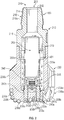
- FIG. 3 shows a cross-section of a force application device 300 not in accordance with the present invention.
- the device 300 may be made in the form of a unit or capsule for placement in the fluid channel of a drill bit, such as drill bit 150 shown in FIG. 2 .
- the device 300 may also be made in any number of subassemblies or components.
- the device 300 shown includes an upper chamber 302 that houses an electric motor 310 that may be operated by a battery (not shown) in the drill bit or by electric power generated by a power unit in the drilling assembly, such as the power unit 179 shown in FIG. 1 .
- the electric motor 310 is coupled to a rotation reduction device 320, such as a reduction gear, via a coupling 322.
- the reduction gear 320 housed in a housing 304 rotates a drive shaft 324 attached to the reduction gear 320 at rotational speed lower than the rotational speed of the motor 310 by a known factor.
- the drive shaft 324 may be coupled to or decoupled from a rotational drive member 340, such as a drive screw, by a coupling device 330.
- the coupling device 330 may be operated by electrical current supplied from a battery in the drill bit (not shown) or a power generation unit, such as power generation unit 179 in the drilling assembly 130 shown in FIG . 1 . In one configuration, when no current is supplied to the coupling device 330, it is in a deactivated mode and does not couple the drive shaft 324 to the drive screw 340.
- the coupling device 330 When the coupling device 330 is activated by supplying current thereto, it couples or connects the drive shaft 324 to the drive screw 340.
- the motor 310 When the motor 310 is rotated in a first direction, for example clockwise, when the drive shaft 324 and the drive screw 340 are coupled by the coupling device 330, the drive shaft 324 will rotate the drive screw 340 in a first rotational direction, e.g., clockwise.
- the drive screw 340 When the current to the motor 310 is reversed when the drive shaft 324 is coupled to the drive screw 340, the drive screw 340 will rotate in a second direction, i.e., in this case opposite to the first direction, i.e., counterclockwise.
- the force application device 300 further may further include a drive member 350, such as a nut, in a chamber 360, that is coupled to the drive screw 340 so that when the drive screw 340 rotates in one direction, the nut 350 moves linearly in a first direction (for example downward) and when the drive screw 340 moves in a second direction (opposite to the first direction), the nut 350 moves in a second direction, i.e., in this case upward.
- the nut 350 is connected to a pin member or pusher 380.
- the pin member 380 moves upward when the nut 340 moves upward and moves downward when the nut 340 moves downward.
- Bearings 335 may be provided around the drive screw 340 to provide lateral support to the drive screw 340.
- Seals 355a and 355b may be placed between the nut 350 and a housing 370 enclosing the chamber 360.
- the pin 380 is configured to apply force on the drive unit, such as drive unit 245 shown in FIG.1 .
- the drive unit 245 shown in FIG.1 .
- the pin 380 causes the pads 240a and 240b ( FIG. 2 ) to extend from the drill bit surface and when the pin 380 moves upward, the biasing member in the drive unit 245 causes the pads 240a and 240b to retract from the drill bit surface.
- a pressure compensator 375 such as bellows may be provided to provide pressure compensation to the electric motor 310 and other components in the force application device 300.
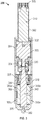
- FIG. 4 shows a cross-section of a force application device 400 in accordance with the present invention.
- the force application device 400 is similar to the device 300 shown in FIG. 3 , but includes an alternative drive unit 490 for moving the pin 480.
- the force application device 400 may be made in the form of a unit or capsule for placement in the fluid channel of a drill bit, such as drill bit 150 shown in FIG. 2 .
- the device 400 includes an upper chamber 402 that houses an electric motor 410 that may be operated by a battery (not shown) in the drill bit or by electric power generated by a power unit in the drilling assembly, such as the power unit 179 shown in FIG. 1 .
- the electric motor 410 is coupled to a rotation reduction device 420, such as a reduction gear, via a coupling 422.
- the reduction gear 420 rotates a drive shaft 424 attached to the reduction gear 420 at a rotational speed lower than the rotational speed of the motor 410 by a known factor.
- the drive shaft 424 may be coupled to or decoupled from a rotational drive member 440, such as a drive screw, by a coupling device 430, which coupling device may be operated by electrical current supplied from the battery in the drill bit (not shown) or a power generation unit, such as power generation unit 179 in the drilling assembly 130 ( FIG.1 ). When no current is supplied to the coupling device 430, it is in a deactivated mode and does not couple the drive shaft 424 to the drive screw 440.
- the coupling device 430 When the coupling device 430 is activated by supplying current thereto, it couples or connects the drive shaft 424 to the drive screw 440.
- the motor 410 When the motor 410 is rotated in a first direction, for example clockwise, when the drive shaft 324 and the drive screw 340 are coupled by the coupling device 430, the drive shaft 424 will rotate the drive screw 440 in a first rotational direction, e.g., in this case clockwise.
- the drive screw 440 When the current to the motor 410 is reversed when the drive shaft 424 is coupled to the drive screw 440, the drive screw 440 will rotate in a second direction, i.e., in this case opposite to the first direction, i.e., counterclockwise.
- the force application device 400 further includes a drive member 450, such as a nut, in a chamber 460, that is coupled to the drive screw 440 so that when the drive screw 440 rotates in one direction, the nut 450 moves linearly in a first direction (for example downward) and when the drive screw 440 moves in a second direction (opposite to the first direction), the nut 450 moves in a second direction, i.e., in this case upward.
- the nut 450 drives a shaft 475 that in turn drives a drive mechanism 490.
- the drive mechanism 490 includes a lever member 491 connected to an extension member 477 of the shaft 475 by a coupling member 492, such as a pin or another suitable attachment member.
- the lever 491 is connected to the pin member 480 in a manner that when the shaft 475 moves downward, it moves the lever downward that in turn causes the pin 480 to move downward.
- the lever 491 moves upward and causes the pin 480 to move upward.
- a sensor 495 may be attached to the shaft 475 or placed at another suitable location to provide signals relating to the linear movement of the pin shaft 475 and thus the pin 480.
- the sensor may be any suitable sensor configured to provide signals relative to the motion of the pin.
- the sensor 395 may include, but is not limited to, a hall-effect sensor and a linear potentiometer sensor.
- the sensor 495 signals are processed by electrical circuits in the drill bit or in the drilling assembly and a controller in response thereto may control the motor rotation and thus the movement of the pin 480 and the pads.
- a pressure compensation device 315 such as bellows, may be provided to provide pressure compensation to the motor electric 410 and other components in the force application device 400.
- drill bits such as a PDC bits
- Such drill bits aid in: (a) steerability of the bit (b) dampening the level of vibrations and (c) reducing the severity of stick-slip while drilling, among other aspects.
- Moving the pads up and down changes the drilling characteristic of the bit.
- the electrical power may be provided from batteries in the drill bit or a power unit in the drilling assembly.
- a controller may control the operation of the motor and thus the extension and retraction of the pads in response to a parameter of interest or an event, including but not limited to vibration levels, torsional oscillations, high torque values; stick slip, and lateral movement.
Landscapes
- Engineering & Computer Science (AREA)
- Life Sciences & Earth Sciences (AREA)
- Geology (AREA)
- Mining & Mineral Resources (AREA)
- Mechanical Engineering (AREA)
- Physics & Mathematics (AREA)
- Environmental & Geological Engineering (AREA)
- Fluid Mechanics (AREA)
- General Life Sciences & Earth Sciences (AREA)
- Geochemistry & Mineralogy (AREA)
- Earth Drilling (AREA)
Claims (15)
- Trépan (150), comprenant :un patin (240a, b) configuré pour s'étendre et se rétracter depuis une surface (232) du trépan (150) ; etun dispositif d'application de force (400) configuré pour étendre le patin (240a, b) depuis la surface (232) du trépan (150), le dispositif d'application de force (400) incluant un moteur électrique (410) ;caractérisé en ce que le moteur électrique (410) fait tourner une vis d'entraînement (440), et en ce que le dispositif d'application de force (400) inclut :une noix d'entraînement (450) couplée à la vis d'entraînement (440), dans laquelle la rotation de vis d'entraînement dans un premier sens amène la noix d'entraînement (450) à se déplacer dans un premier sens linéaire et la rotation de la vis d'entraînement (440) dans un second sens amène la noix d'entraînement (450) à se déplacer dans un second sens linéaire ; etun arbre d'entraînement (424) couplé à la noix d'entraînement (450) configuré pour exercer une force sur le patin (240a, b) pour étendre le patin (240a, b) depuis la surface (232) du trépan (150) ;dans lequel l'arbre d'entraînement (424) exerce une force sur un levier (491) qui applique une force sur une unité d'entraînement (490) pour amener l'unité d'entraînement (490) à étendre le patin depuis la surface (232) du trépan (150).
- Trépan (150) selon la revendication 1, comprenant en outre un dispositif formant palier configuré pour fournir un support latéral à la vis d'entraînement (440).
- Trépan (150) selon la revendication 1, comprenant en outre un soufflet (375) configuré pour fournir un équilibre de pression entre un composant dans le dispositif d'application de force (400) et un élément à l'extérieur du dispositif d'application de force (400) ; de manière facultative dans lequel l'unité d'entraînement (490) inclut un dispositif de sollicitation (248) configuré pour amener le patin (240a, b) à se rétracter depuis la surface (232) du trépan (150) quand la force exercée sur le patin (240a, b) est supprimée.
- Trépan (150) selon la revendication 1, comprenant en outre un capteur (143) configuré pour fournir des signaux correspondant à un mouvement se rapportant à un mouvement du patin (240a, b).
- Appareil de forage comprenant :un ensemble de forage (140) ayant le trépan (150) selon la revendication 1 au niveau d'une extrémité de ce dernier.
- Appareil de forage selon la revendication 5, comprenant en outre un capteur (143) configuré pour fournir des signaux ; de manière facultative comprenant en outre une unité de commande configurée pour commander la rotation du moteur (410) en réponse un paramètre d'intérêt.
- Appareil de forage selon la revendication 6, dans lequel le paramètre d'intérêt est sélectionné dans un groupe constitué par : (i) le mordant du trépan ; (ii) les vibrations ; (iii) le broutage ; (iv) le mouvement latéral du trépan ; et (v) la capacité de braquage du trépan.
- Appareil de forage selon la revendication 6, dans lequel l'unité de commande est placée au niveau d'un emplacement sélectionné dans un groupe d'emplacements constitué par : (i) dans le trépan ; (ii) dans l'ensemble de forage ; (iii) au niveau de la surface ; et (iv) partiellement au niveau de deux ou plus parmi le trépan, l'ensemble de forage et la surface.
- Trépan (150) selon la revendication 1 ou appareil de forage selon la revendication 5, dans lequel l'arbre d'entraînement (424) exerce une force sur une unité d'entraînement (490) reliée au patin (240a, b) qui étend le patin (240a, b) depuis la surface (232) du trépan.
- Trépan (150) selon la revendication 1 ou appareil de forage selon la revendication 5, comprenant en outre un dispositif d'accouplement (430) configuré pour relier de manière sélective le moteur (410) à la vis d'entraînement (440) et pour désaccoupler le moteur (410) de la vis d'entraînement (440).
- Trépan (150) selon la revendication 1, ou appareil de forage selon la revendication 5, comprenant en outre un dispositif de réduction de vitesse (420) entre le moteur (410) et la vis d'entraînement (440) configuré pour réduire la vitesse de rotation de la vis d'entraînement (440) au-dessous de la vitesse de rotation du moteur (410).
- Trépan (150) selon la revendication 1, comprenant en outre un dispositif de compensation de pression (375) configuré pour fournir un équilibre de pression entre un composant dans le dispositif d'application de force (400) et un élément à l'extérieur du dispositif d'application de force (400).
- Trépan (150) selon la revendication 1 ou appareil de forage selon la revendication 5, comprenant en outre une unité d'entraînement (490) entre le dispositif d'application de force (400) et le patin (240a, b) configurée pour déplacer le patin (240a, b) pour le rétracter depuis la surface (232) du trépan (150) quand la force exercée sur le patin (240a, b) est supprimée.
- Procédé de fabrication d'un trépan (150) comprenant :la fourniture d'un corps de trépan (210) ayant un patin (240a, b) configuré pour s'étendre depuis une surface (232) de ce dernier ;la fourniture d'un dispositif d'application de force (400) qui inclut un moteur électrique (410), caractérisé en ce que le moteur électrique (410) fait tourner une vis d'entraînement (440), et en ce que le dispositif d'application de force (400) inclut une noix d'entraînement (430) couplée à la vis d'entraînement (440), dans lequel la rotation de la vis d'entraînement (440) dans un premier sens amène la noix d'entraînement (450) à se déplacer dans un premier sens linéaire et la rotation de la vis d'entraînement (440) dans un second sens amène la noix d'entraînement (450) à se déplacer dans un second sens linéaire, et un arbre d'entraînement (424) couplé à la noix d'entraînement (450) configuré pour exercer une force sur le patin (240a, b) pour étendre le patin (240a, b) depuis la surface (232) du trépan (150), dans lequel l'arbre d'entraînement (424) exerce une force sur un levier (491) qui applique une force sur une unité d'entraînement (490) pour amener l'unité d'entraînement (490) à étendre le patin depuis la surface du trépan ; etle placement sûr du dispositif d'application de force (400) à l'intérieur du corps de trépan (210).
- Procédé de forage d'un puits de forage, comprenant :le transport d'un foret ayant le trépan (150) selon la revendication 1 au niveau d'une extrémité de ce dernier ; etle forage du puits de forage avec le train de tiges de forage.
Applications Claiming Priority (2)
| Application Number | Priority Date | Filing Date | Title |
|---|---|---|---|
| US13/561,897 US9181756B2 (en) | 2012-07-30 | 2012-07-30 | Drill bit with a force application using a motor and screw mechanism for controlling extension of a pad in the drill bit |
| PCT/US2013/052615 WO2014022335A1 (fr) | 2012-07-30 | 2013-07-30 | Trépan avec application de force utilisant un moteur et un mécanisme à vis pour commander l'extension d'un patin dans le trépan |
Publications (4)
| Publication Number | Publication Date |
|---|---|
| EP2880246A1 EP2880246A1 (fr) | 2015-06-10 |
| EP2880246A4 EP2880246A4 (fr) | 2016-06-08 |
| EP2880246B1 true EP2880246B1 (fr) | 2018-01-10 |
| EP2880246B8 EP2880246B8 (fr) | 2018-02-21 |
Family
ID=49993768
Family Applications (1)
| Application Number | Title | Priority Date | Filing Date |
|---|---|---|---|
| EP13825665.6A Active EP2880246B8 (fr) | 2012-07-30 | 2013-07-30 | Trépan avec application de force utilisant un moteur et un mécanisme à vis pour commander l'extension d'un patin dans le trépan |
Country Status (5)
| Country | Link |
|---|---|
| US (1) | US9181756B2 (fr) |
| EP (1) | EP2880246B8 (fr) |
| CA (1) | CA2880693C (fr) |
| NO (1) | NO2970926T3 (fr) |
| WO (1) | WO2014022335A1 (fr) |
Families Citing this family (17)
| Publication number | Priority date | Publication date | Assignee | Title |
|---|---|---|---|---|
| US9759014B2 (en) | 2013-05-13 | 2017-09-12 | Baker Hughes Incorporated | Earth-boring tools including movable formation-engaging structures and related methods |
| US10502001B2 (en) | 2014-05-07 | 2019-12-10 | Baker Hughes, A Ge Company, Llc | Earth-boring tools carrying formation-engaging structures |
| WO2016059972A1 (fr) * | 2014-10-14 | 2016-04-21 | 東レ株式会社 | Composition de semi-conducteur organique, élément photovoltaïque, dispositif de conversion photoélectrique, et procédé de fabrication d'élément photovoltaïque |
| US10494871B2 (en) | 2014-10-16 | 2019-12-03 | Baker Hughes, A Ge Company, Llc | Modeling and simulation of drill strings with adaptive systems |
| WO2016153499A1 (fr) * | 2015-03-25 | 2016-09-29 | Halliburton Energy Services, Inc. | Commande de profondeur de coupe réglable destiné à un outil de forage de fond de trou |
| US10273759B2 (en) | 2015-12-17 | 2019-04-30 | Baker Hughes Incorporated | Self-adjusting earth-boring tools and related systems and methods |
| US10280479B2 (en) | 2016-01-20 | 2019-05-07 | Baker Hughes, A Ge Company, Llc | Earth-boring tools and methods for forming earth-boring tools using shape memory materials |
| US10487589B2 (en) | 2016-01-20 | 2019-11-26 | Baker Hughes, A Ge Company, Llc | Earth-boring tools, depth-of-cut limiters, and methods of forming or servicing a wellbore |
| US10508323B2 (en) | 2016-01-20 | 2019-12-17 | Baker Hughes, A Ge Company, Llc | Method and apparatus for securing bodies using shape memory materials |
| GB2561317A (en) * | 2016-02-26 | 2018-10-10 | Halliburton Energy Services Inc | Hybrid drill bit with axially adjustable counter-rotation cutters in center |
| US10633929B2 (en) | 2017-07-28 | 2020-04-28 | Baker Hughes, A Ge Company, Llc | Self-adjusting earth-boring tools and related systems |
| WO2019035838A1 (fr) * | 2017-08-17 | 2019-02-21 | Halliburton Energy Services, Inc. | Trépan à configuration de jauge interne réglable |
| US12018556B2 (en) | 2018-08-29 | 2024-06-25 | Schlumberger Technology Corporation | Systems and methods of controlling downhole behavior |
| US11795763B2 (en) | 2020-06-11 | 2023-10-24 | Schlumberger Technology Corporation | Downhole tools having radially extendable elements |
| CN114718465B (zh) * | 2022-04-18 | 2023-05-26 | 中南大学 | 一种动态拉剪掘进钻头及复合破岩方法 |
| US12286839B2 (en) | 2022-10-05 | 2025-04-29 | Schlumberger Technology Corporation | Devices and systems for cutting element assemblies |
| US12270255B1 (en) * | 2024-01-10 | 2025-04-08 | Halliburton Energy Services, Inc. | Multiple selectable pressure driven devices on a drill bit |
Family Cites Families (33)
| Publication number | Priority date | Publication date | Assignee | Title |
|---|---|---|---|---|
| US1860214A (en) | 1931-03-07 | 1932-05-24 | Morris C Yeaman | Hydraulic rotary drilling bit |
| US3807512A (en) | 1972-12-29 | 1974-04-30 | Texaco Inc | Percussion-rotary drilling mechanism with mud drive turbine |
| US4185704A (en) | 1978-05-03 | 1980-01-29 | Maurer Engineering Inc. | Directional drilling apparatus |
| HU184664B (en) | 1979-03-14 | 1984-09-28 | Olajipari Foevallal Tervezoe | Hydraulic drilling motor for deep drilling |
| US4281722A (en) | 1979-05-15 | 1981-08-04 | Long Year Company | Retractable bit system |
| WO1983000524A1 (fr) | 1981-08-07 | 1983-02-17 | Kaalstad, Oscar, William | Dispositif de forage |
| US4676310A (en) | 1982-07-12 | 1987-06-30 | Scherbatskoy Serge Alexander | Apparatus for transporting measuring and/or logging equipment in a borehole |
| US4940097A (en) | 1988-12-13 | 1990-07-10 | Martini Leo A | Fluid powered rotary percussion drill with formation disintegration inserts |
| BE1006434A3 (fr) | 1992-12-04 | 1994-08-23 | Baroid Technology Inc | Commande d'au moins deux bras de stabilisation dans un dispositif de forage ou de carottage. |
| US5682957A (en) | 1995-12-21 | 1997-11-04 | Ingersoll-Rand Company | Water separator for a down hole drill |
| GB2322651B (en) | 1996-11-06 | 2000-09-20 | Camco Drilling Group Ltd | A downhole unit for use in boreholes in a subsurface formation |
| US7004263B2 (en) | 2001-05-09 | 2006-02-28 | Schlumberger Technology Corporation | Directional casing drilling |
| US6840336B2 (en) | 2001-06-05 | 2005-01-11 | Schlumberger Technology Corporation | Drilling tool with non-rotating sleeve |
| US7392859B2 (en) | 2004-03-17 | 2008-07-01 | Western Well Tool, Inc. | Roller link toggle gripper and downhole tractor |
| US7641003B2 (en) * | 2005-11-21 | 2010-01-05 | David R Hall | Downhole hammer assembly |
| US7360610B2 (en) | 2005-11-21 | 2008-04-22 | Hall David R | Drill bit assembly for directional drilling |
| US7484576B2 (en) | 2006-03-23 | 2009-02-03 | Hall David R | Jack element in communication with an electric motor and or generator |
| US8297375B2 (en) | 2005-11-21 | 2012-10-30 | Schlumberger Technology Corporation | Downhole turbine |
| US7516782B2 (en) | 2006-02-09 | 2009-04-14 | Schlumberger Technology Corporation | Self-anchoring device with force amplification |
| US7389832B2 (en) * | 2006-05-26 | 2008-06-24 | Dyna-Drill Technologies, Inc. | Hydrostatic mechanical seal with local pressurization of seal interface |
| US7866416B2 (en) | 2007-06-04 | 2011-01-11 | Schlumberger Technology Corporation | Clutch for a jack element |
| US7770667B2 (en) * | 2007-06-14 | 2010-08-10 | Wwt International, Inc. | Electrically powered tractor |
| US8763726B2 (en) | 2007-08-15 | 2014-07-01 | Schlumberger Technology Corporation | Drill bit gauge pad control |
| US7836975B2 (en) | 2007-10-24 | 2010-11-23 | Schlumberger Technology Corporation | Morphable bit |
| US7434634B1 (en) | 2007-11-14 | 2008-10-14 | Hall David R | Downhole turbine |
| US8960329B2 (en) * | 2008-07-11 | 2015-02-24 | Schlumberger Technology Corporation | Steerable piloted drill bit, drill system, and method of drilling curved boreholes |
| US8205686B2 (en) | 2008-09-25 | 2012-06-26 | Baker Hughes Incorporated | Drill bit with adjustable axial pad for controlling torsional fluctuations |
| US8365843B2 (en) | 2009-02-24 | 2013-02-05 | Schlumberger Technology Corporation | Downhole tool actuation |
| US8087479B2 (en) | 2009-08-04 | 2012-01-03 | Baker Hughes Incorporated | Drill bit with an adjustable steering device |
| US8689905B2 (en) | 2009-11-24 | 2014-04-08 | Baker Hughes Incorporated | Drilling assembly with steering unit integrated in drilling motor |
| US9103175B2 (en) * | 2012-07-30 | 2015-08-11 | Baker Hughes Incorporated | Drill bit with hydraulically-activated force application device for controlling depth-of-cut of the drill bit |
| US9140074B2 (en) | 2012-07-30 | 2015-09-22 | Baker Hughes Incorporated | Drill bit with a force application device using a lever device for controlling extension of a pad from a drill bit surface |
| US9255449B2 (en) * | 2012-07-30 | 2016-02-09 | Baker Hughes Incorporated | Drill bit with electrohydraulically adjustable pads for controlling depth of cut |
-
2012
- 2012-07-30 US US13/561,897 patent/US9181756B2/en active Active
-
2013
- 2013-07-30 WO PCT/US2013/052615 patent/WO2014022335A1/fr not_active Ceased
- 2013-07-30 EP EP13825665.6A patent/EP2880246B8/fr active Active
- 2013-07-30 CA CA2880693A patent/CA2880693C/fr active Active
-
2014
- 2014-03-12 NO NO14713925A patent/NO2970926T3/no unknown
Non-Patent Citations (1)
| Title |
|---|
| None * |
Also Published As
| Publication number | Publication date |
|---|---|
| CA2880693A1 (fr) | 2014-02-06 |
| EP2880246B8 (fr) | 2018-02-21 |
| CA2880693C (fr) | 2017-06-20 |
| US9181756B2 (en) | 2015-11-10 |
| EP2880246A1 (fr) | 2015-06-10 |
| US20140027176A1 (en) | 2014-01-30 |
| WO2014022335A1 (fr) | 2014-02-06 |
| NO2970926T3 (fr) | 2018-06-30 |
| EP2880246A4 (fr) | 2016-06-08 |
Similar Documents
| Publication | Publication Date | Title |
|---|---|---|
| EP2880246B1 (fr) | Trépan avec application de force utilisant un moteur et un mécanisme à vis pour commander l'extension d'un patin dans le trépan | |
| EP2880241B1 (fr) | Trépan avec patins ajustable hydrauliquement pour commander la profondeur de coupe | |
| US9140074B2 (en) | Drill bit with a force application device using a lever device for controlling extension of a pad from a drill bit surface | |
| CA2880696C (fr) | Trepan avec dispositif d'application de force commande hydrauliquement pour commander la profondeur de coupe du trepan | |
| EP2971439B1 (fr) | Trépan avec éléments d'extension en communication hydraulique pour régler les charges sur ce dernier | |
| CA2909627C (fr) | Trepan a plaquettes auto-ajustables | |
| US9273522B2 (en) | Steering head with integrated drilling dynamics control | |
| US8960328B2 (en) | Drill bit with adjustable side force | |
| US20150129311A1 (en) | Motor Integrated Reamer | |
| WO2013070479A1 (fr) | Appareil de forage comprenant des dispositifs de meulage configurés de façon à tourner à des vitesses différentes |
Legal Events
| Date | Code | Title | Description |
|---|---|---|---|
| PUAI | Public reference made under article 153(3) epc to a published international application that has entered the european phase |
Free format text: ORIGINAL CODE: 0009012 |
|
| 17P | Request for examination filed |
Effective date: 20150224 |
|
| AK | Designated contracting states |
Kind code of ref document: A1 Designated state(s): AL AT BE BG CH CY CZ DE DK EE ES FI FR GB GR HR HU IE IS IT LI LT LU LV MC MK MT NL NO PL PT RO RS SE SI SK SM TR |
|
| AX | Request for extension of the european patent |
Extension state: BA ME |
|
| RIN1 | Information on inventor provided before grant (corrected) |
Inventor name: SCHWEFE, THORSTEN Inventor name: RINBERG, GREGORY Inventor name: RAZ, DAN |
|
| DAX | Request for extension of the european patent (deleted) | ||
| RA4 | Supplementary search report drawn up and despatched (corrected) |
Effective date: 20160506 |
|
| RIC1 | Information provided on ipc code assigned before grant |
Ipc: E21B 7/04 20060101AFI20160429BHEP Ipc: E21B 4/00 20060101ALI20160429BHEP |
|
| GRAP | Despatch of communication of intention to grant a patent |
Free format text: ORIGINAL CODE: EPIDOSNIGR1 |
|
| STAA | Information on the status of an ep patent application or granted ep patent |
Free format text: STATUS: GRANT OF PATENT IS INTENDED |
|
| INTG | Intention to grant announced |
Effective date: 20170725 |
|
| GRAS | Grant fee paid |
Free format text: ORIGINAL CODE: EPIDOSNIGR3 |
|
| GRAA | (expected) grant |
Free format text: ORIGINAL CODE: 0009210 |
|
| STAA | Information on the status of an ep patent application or granted ep patent |
Free format text: STATUS: THE PATENT HAS BEEN GRANTED |
|
| AK | Designated contracting states |
Kind code of ref document: B1 Designated state(s): AL AT BE BG CH CY CZ DE DK EE ES FI FR GB GR HR HU IE IS IT LI LT LU LV MC MK MT NL NO PL PT RO RS SE SI SK SM TR |
|
| REG | Reference to a national code |
Ref country code: CH Ref legal event code: EP Ref country code: AT Ref legal event code: REF Ref document number: 962622 Country of ref document: AT Kind code of ref document: T Effective date: 20180115 |
|
| RAP2 | Party data changed (patent owner data changed or rights of a patent transferred) |
Owner name: BAKER HUGHES, A GE COMPANY, LLC |
|
| REG | Reference to a national code |
Ref country code: IE Ref legal event code: FG4D |
|
| REG | Reference to a national code |
Ref country code: DE Ref legal event code: R096 Ref document number: 602013031975 Country of ref document: DE |
|
| REG | Reference to a national code |
Ref country code: NO Ref legal event code: T2 Effective date: 20180110 |
|
| REG | Reference to a national code |
Ref country code: NL Ref legal event code: MP Effective date: 20180110 |
|
| REG | Reference to a national code |
Ref country code: AT Ref legal event code: MK05 Ref document number: 962622 Country of ref document: AT Kind code of ref document: T Effective date: 20180110 |
|
| PG25 | Lapsed in a contracting state [announced via postgrant information from national office to epo] |
Ref country code: NL Free format text: LAPSE BECAUSE OF FAILURE TO SUBMIT A TRANSLATION OF THE DESCRIPTION OR TO PAY THE FEE WITHIN THE PRESCRIBED TIME-LIMIT Effective date: 20180110 |
|
| PG25 | Lapsed in a contracting state [announced via postgrant information from national office to epo] |
Ref country code: CY Free format text: LAPSE BECAUSE OF FAILURE TO SUBMIT A TRANSLATION OF THE DESCRIPTION OR TO PAY THE FEE WITHIN THE PRESCRIBED TIME-LIMIT Effective date: 20180110 Ref country code: LT Free format text: LAPSE BECAUSE OF FAILURE TO SUBMIT A TRANSLATION OF THE DESCRIPTION OR TO PAY THE FEE WITHIN THE PRESCRIBED TIME-LIMIT Effective date: 20180110 Ref country code: HR Free format text: LAPSE BECAUSE OF FAILURE TO SUBMIT A TRANSLATION OF THE DESCRIPTION OR TO PAY THE FEE WITHIN THE PRESCRIBED TIME-LIMIT Effective date: 20180110 Ref country code: ES Free format text: LAPSE BECAUSE OF FAILURE TO SUBMIT A TRANSLATION OF THE DESCRIPTION OR TO PAY THE FEE WITHIN THE PRESCRIBED TIME-LIMIT Effective date: 20180110 Ref country code: FI Free format text: LAPSE BECAUSE OF FAILURE TO SUBMIT A TRANSLATION OF THE DESCRIPTION OR TO PAY THE FEE WITHIN THE PRESCRIBED TIME-LIMIT Effective date: 20180110 |
|
| PG25 | Lapsed in a contracting state [announced via postgrant information from national office to epo] |
Ref country code: RS Free format text: LAPSE BECAUSE OF FAILURE TO SUBMIT A TRANSLATION OF THE DESCRIPTION OR TO PAY THE FEE WITHIN THE PRESCRIBED TIME-LIMIT Effective date: 20180110 Ref country code: AT Free format text: LAPSE BECAUSE OF FAILURE TO SUBMIT A TRANSLATION OF THE DESCRIPTION OR TO PAY THE FEE WITHIN THE PRESCRIBED TIME-LIMIT Effective date: 20180110 Ref country code: PL Free format text: LAPSE BECAUSE OF FAILURE TO SUBMIT A TRANSLATION OF THE DESCRIPTION OR TO PAY THE FEE WITHIN THE PRESCRIBED TIME-LIMIT Effective date: 20180110 Ref country code: BG Free format text: LAPSE BECAUSE OF FAILURE TO SUBMIT A TRANSLATION OF THE DESCRIPTION OR TO PAY THE FEE WITHIN THE PRESCRIBED TIME-LIMIT Effective date: 20180410 Ref country code: GR Free format text: LAPSE BECAUSE OF FAILURE TO SUBMIT A TRANSLATION OF THE DESCRIPTION OR TO PAY THE FEE WITHIN THE PRESCRIBED TIME-LIMIT Effective date: 20180411 Ref country code: LV Free format text: LAPSE BECAUSE OF FAILURE TO SUBMIT A TRANSLATION OF THE DESCRIPTION OR TO PAY THE FEE WITHIN THE PRESCRIBED TIME-LIMIT Effective date: 20180110 Ref country code: SE Free format text: LAPSE BECAUSE OF FAILURE TO SUBMIT A TRANSLATION OF THE DESCRIPTION OR TO PAY THE FEE WITHIN THE PRESCRIBED TIME-LIMIT Effective date: 20180110 Ref country code: IS Free format text: LAPSE BECAUSE OF FAILURE TO SUBMIT A TRANSLATION OF THE DESCRIPTION OR TO PAY THE FEE WITHIN THE PRESCRIBED TIME-LIMIT Effective date: 20180510 |
|
| REG | Reference to a national code |
Ref country code: DE Ref legal event code: R097 Ref document number: 602013031975 Country of ref document: DE |
|
| PG25 | Lapsed in a contracting state [announced via postgrant information from national office to epo] |
Ref country code: AL Free format text: LAPSE BECAUSE OF FAILURE TO SUBMIT A TRANSLATION OF THE DESCRIPTION OR TO PAY THE FEE WITHIN THE PRESCRIBED TIME-LIMIT Effective date: 20180110 Ref country code: RO Free format text: LAPSE BECAUSE OF FAILURE TO SUBMIT A TRANSLATION OF THE DESCRIPTION OR TO PAY THE FEE WITHIN THE PRESCRIBED TIME-LIMIT Effective date: 20180110 Ref country code: EE Free format text: LAPSE BECAUSE OF FAILURE TO SUBMIT A TRANSLATION OF THE DESCRIPTION OR TO PAY THE FEE WITHIN THE PRESCRIBED TIME-LIMIT Effective date: 20180110 Ref country code: IT Free format text: LAPSE BECAUSE OF FAILURE TO SUBMIT A TRANSLATION OF THE DESCRIPTION OR TO PAY THE FEE WITHIN THE PRESCRIBED TIME-LIMIT Effective date: 20180110 |
|
| PLBE | No opposition filed within time limit |
Free format text: ORIGINAL CODE: 0009261 |
|
| STAA | Information on the status of an ep patent application or granted ep patent |
Free format text: STATUS: NO OPPOSITION FILED WITHIN TIME LIMIT |
|
| PG25 | Lapsed in a contracting state [announced via postgrant information from national office to epo] |
Ref country code: SK Free format text: LAPSE BECAUSE OF FAILURE TO SUBMIT A TRANSLATION OF THE DESCRIPTION OR TO PAY THE FEE WITHIN THE PRESCRIBED TIME-LIMIT Effective date: 20180110 Ref country code: CZ Free format text: LAPSE BECAUSE OF FAILURE TO SUBMIT A TRANSLATION OF THE DESCRIPTION OR TO PAY THE FEE WITHIN THE PRESCRIBED TIME-LIMIT Effective date: 20180110 Ref country code: DK Free format text: LAPSE BECAUSE OF FAILURE TO SUBMIT A TRANSLATION OF THE DESCRIPTION OR TO PAY THE FEE WITHIN THE PRESCRIBED TIME-LIMIT Effective date: 20180110 Ref country code: SM Free format text: LAPSE BECAUSE OF FAILURE TO SUBMIT A TRANSLATION OF THE DESCRIPTION OR TO PAY THE FEE WITHIN THE PRESCRIBED TIME-LIMIT Effective date: 20180110 |
|
| 26N | No opposition filed |
Effective date: 20181011 |
|
| REG | Reference to a national code |
Ref country code: DE Ref legal event code: R119 Ref document number: 602013031975 Country of ref document: DE |
|
| PG25 | Lapsed in a contracting state [announced via postgrant information from national office to epo] |
Ref country code: SI Free format text: LAPSE BECAUSE OF FAILURE TO SUBMIT A TRANSLATION OF THE DESCRIPTION OR TO PAY THE FEE WITHIN THE PRESCRIBED TIME-LIMIT Effective date: 20180110 |
|
| REG | Reference to a national code |
Ref country code: CH Ref legal event code: PL |
|
| PG25 | Lapsed in a contracting state [announced via postgrant information from national office to epo] |
Ref country code: MC Free format text: LAPSE BECAUSE OF FAILURE TO SUBMIT A TRANSLATION OF THE DESCRIPTION OR TO PAY THE FEE WITHIN THE PRESCRIBED TIME-LIMIT Effective date: 20180110 Ref country code: LU Free format text: LAPSE BECAUSE OF NON-PAYMENT OF DUE FEES Effective date: 20180730 |
|
| REG | Reference to a national code |
Ref country code: BE Ref legal event code: MM Effective date: 20180731 |
|
| PG25 | Lapsed in a contracting state [announced via postgrant information from national office to epo] |
Ref country code: FR Free format text: LAPSE BECAUSE OF NON-PAYMENT OF DUE FEES Effective date: 20180731 Ref country code: CH Free format text: LAPSE BECAUSE OF NON-PAYMENT OF DUE FEES Effective date: 20180731 Ref country code: DE Free format text: LAPSE BECAUSE OF NON-PAYMENT OF DUE FEES Effective date: 20190201 Ref country code: LI Free format text: LAPSE BECAUSE OF NON-PAYMENT OF DUE FEES Effective date: 20180731 |
|
| REG | Reference to a national code |
Ref country code: IE Ref legal event code: MM4A |
|
| PG25 | Lapsed in a contracting state [announced via postgrant information from national office to epo] |
Ref country code: BE Free format text: LAPSE BECAUSE OF NON-PAYMENT OF DUE FEES Effective date: 20180731 |
|
| PG25 | Lapsed in a contracting state [announced via postgrant information from national office to epo] |
Ref country code: IE Free format text: LAPSE BECAUSE OF NON-PAYMENT OF DUE FEES Effective date: 20180730 |
|
| PG25 | Lapsed in a contracting state [announced via postgrant information from national office to epo] |
Ref country code: MT Free format text: LAPSE BECAUSE OF NON-PAYMENT OF DUE FEES Effective date: 20180730 |
|
| PG25 | Lapsed in a contracting state [announced via postgrant information from national office to epo] |
Ref country code: TR Free format text: LAPSE BECAUSE OF FAILURE TO SUBMIT A TRANSLATION OF THE DESCRIPTION OR TO PAY THE FEE WITHIN THE PRESCRIBED TIME-LIMIT Effective date: 20180110 |
|
| PG25 | Lapsed in a contracting state [announced via postgrant information from national office to epo] |
Ref country code: HU Free format text: LAPSE BECAUSE OF FAILURE TO SUBMIT A TRANSLATION OF THE DESCRIPTION OR TO PAY THE FEE WITHIN THE PRESCRIBED TIME-LIMIT; INVALID AB INITIO Effective date: 20130730 Ref country code: PT Free format text: LAPSE BECAUSE OF FAILURE TO SUBMIT A TRANSLATION OF THE DESCRIPTION OR TO PAY THE FEE WITHIN THE PRESCRIBED TIME-LIMIT Effective date: 20180110 |
|
| PG25 | Lapsed in a contracting state [announced via postgrant information from national office to epo] |
Ref country code: MK Free format text: LAPSE BECAUSE OF NON-PAYMENT OF DUE FEES Effective date: 20180110 |
|
| P01 | Opt-out of the competence of the unified patent court (upc) registered |
Effective date: 20230526 |
|
| PGFP | Annual fee paid to national office [announced via postgrant information from national office to epo] |
Ref country code: GB Payment date: 20250619 Year of fee payment: 13 |
|
| PGFP | Annual fee paid to national office [announced via postgrant information from national office to epo] |
Ref country code: NO Payment date: 20250623 Year of fee payment: 13 |