EP2880247B1 - Homokinetische bohrstrangverbindung - Google Patents
Homokinetische bohrstrangverbindung Download PDFInfo
- Publication number
- EP2880247B1 EP2880247B1 EP12886854.4A EP12886854A EP2880247B1 EP 2880247 B1 EP2880247 B1 EP 2880247B1 EP 12886854 A EP12886854 A EP 12886854A EP 2880247 B1 EP2880247 B1 EP 2880247B1
- Authority
- EP
- European Patent Office
- Prior art keywords
- ball
- socket
- constant velocity
- axis
- insert
- Prior art date
- Legal status (The legal status is an assumption and is not a legal conclusion. Google has not performed a legal analysis and makes no representation as to the accuracy of the status listed.)
- Not-in-force
Links
- 238000005553 drilling Methods 0.000 claims description 45
- 238000000034 method Methods 0.000 claims description 25
- 238000006073 displacement reaction Methods 0.000 description 4
- 238000006467 substitution reaction Methods 0.000 description 2
- 238000007792 addition Methods 0.000 description 1
- 230000000712 assembly Effects 0.000 description 1
- 238000000429 assembly Methods 0.000 description 1
- 230000015572 biosynthetic process Effects 0.000 description 1
- 238000004891 communication Methods 0.000 description 1
- 239000002131 composite material Substances 0.000 description 1
- 238000012217 deletion Methods 0.000 description 1
- 230000037430 deletion Effects 0.000 description 1
- 230000009977 dual effect Effects 0.000 description 1
- 230000000694 effects Effects 0.000 description 1
- 239000012530 fluid Substances 0.000 description 1
- 238000004519 manufacturing process Methods 0.000 description 1
- 238000012986 modification Methods 0.000 description 1
- 230000004048 modification Effects 0.000 description 1
- 239000013307 optical fiber Substances 0.000 description 1
- 230000000750 progressive effect Effects 0.000 description 1
- 238000012546 transfer Methods 0.000 description 1
- XLYOFNOQVPJJNP-UHFFFAOYSA-N water Substances O XLYOFNOQVPJJNP-UHFFFAOYSA-N 0.000 description 1
- 238000003466 welding Methods 0.000 description 1
Images


Classifications
-
- E—FIXED CONSTRUCTIONS
- E21—EARTH OR ROCK DRILLING; MINING
- E21B—EARTH OR ROCK DRILLING; OBTAINING OIL, GAS, WATER, SOLUBLE OR MELTABLE MATERIALS OR A SLURRY OF MINERALS FROM WELLS
- E21B17/00—Drilling rods or pipes; Flexible drill strings; Kellies; Drill collars; Sucker rods; Cables; Casings; Tubings
- E21B17/02—Couplings; joints
- E21B17/04—Couplings; joints between rod or the like and bit or between rod and rod or the like
- E21B17/05—Swivel joints
-
- E—FIXED CONSTRUCTIONS
- E21—EARTH OR ROCK DRILLING; MINING
- E21B—EARTH OR ROCK DRILLING; OBTAINING OIL, GAS, WATER, SOLUBLE OR MELTABLE MATERIALS OR A SLURRY OF MINERALS FROM WELLS
- E21B17/00—Drilling rods or pipes; Flexible drill strings; Kellies; Drill collars; Sucker rods; Cables; Casings; Tubings
- E21B17/02—Couplings; joints
-
- E—FIXED CONSTRUCTIONS
- E21—EARTH OR ROCK DRILLING; MINING
- E21B—EARTH OR ROCK DRILLING; OBTAINING OIL, GAS, WATER, SOLUBLE OR MELTABLE MATERIALS OR A SLURRY OF MINERALS FROM WELLS
- E21B7/00—Special methods or apparatus for drilling
- E21B7/04—Directional drilling
- E21B7/06—Deflecting the direction of boreholes
- E21B7/067—Deflecting the direction of boreholes with means for locking sections of a pipe or of a guide for a shaft in angular relation, e.g. adjustable bent sub
-
- E—FIXED CONSTRUCTIONS
- E21—EARTH OR ROCK DRILLING; MINING
- E21B—EARTH OR ROCK DRILLING; OBTAINING OIL, GAS, WATER, SOLUBLE OR MELTABLE MATERIALS OR A SLURRY OF MINERALS FROM WELLS
- E21B19/00—Handling rods, casings, tubes or the like outside the borehole, e.g. in the derrick; Apparatus for feeding the rods or cables
- E21B19/18—Connecting or disconnecting drill bit and drilling pipe
-
- E—FIXED CONSTRUCTIONS
- E21—EARTH OR ROCK DRILLING; MINING
- E21B—EARTH OR ROCK DRILLING; OBTAINING OIL, GAS, WATER, SOLUBLE OR MELTABLE MATERIALS OR A SLURRY OF MINERALS FROM WELLS
- E21B4/00—Drives for drilling, used in the borehole
- E21B4/02—Fluid rotary type drives
-
- F—MECHANICAL ENGINEERING; LIGHTING; HEATING; WEAPONS; BLASTING
- F16—ENGINEERING ELEMENTS AND UNITS; GENERAL MEASURES FOR PRODUCING AND MAINTAINING EFFECTIVE FUNCTIONING OF MACHINES OR INSTALLATIONS; THERMAL INSULATION IN GENERAL
- F16D—COUPLINGS FOR TRANSMITTING ROTATION; CLUTCHES; BRAKES
- F16D3/00—Yielding couplings, i.e. with means permitting movement between the connected parts during the drive
- F16D3/16—Universal joints in which flexibility is produced by means of pivots or sliding or rolling connecting parts
- F16D3/26—Hooke's joints or other joints with an equivalent intermediate member to which each coupling part is pivotally or slidably connected
- F16D3/265—Hooke's joints or other joints with an equivalent intermediate member to which each coupling part is pivotally or slidably connected in which one coupling part has a tongue received with the intermediate member(s) in a recess with a transverse axis in the other coupling part
-
- F—MECHANICAL ENGINEERING; LIGHTING; HEATING; WEAPONS; BLASTING
- F16—ENGINEERING ELEMENTS AND UNITS; GENERAL MEASURES FOR PRODUCING AND MAINTAINING EFFECTIVE FUNCTIONING OF MACHINES OR INSTALLATIONS; THERMAL INSULATION IN GENERAL
- F16D—COUPLINGS FOR TRANSMITTING ROTATION; CLUTCHES; BRAKES
- F16D3/00—Yielding couplings, i.e. with means permitting movement between the connected parts during the drive
- F16D3/16—Universal joints in which flexibility is produced by means of pivots or sliding or rolling connecting parts
- F16D3/26—Hooke's joints or other joints with an equivalent intermediate member to which each coupling part is pivotally or slidably connected
- F16D3/30—Hooke's joints or other joints with an equivalent intermediate member to which each coupling part is pivotally or slidably connected in which the coupling is specially adapted to constant velocity-ratio
Definitions
- This disclosure relates generally to equipment utilized and operations performed in conjunction with a subterranean well and, in one example described below, more particularly provides a drill string constant velocity connection.
- Drilling bottom hole assemblies can include a drilling motor which provides for rotation of a drill bit at an end of a drill string.
- a drilling BHA includes a positive displacement Moineau-type drilling motor
- a rotor of the drilling motor may have an articulating, planetary and/or epicyclic motion, which is preferably transformed into rotary motion of the drill bit.
- rotation about one centerline of the BHA is preferably transformed into rotation about another centerline which is not aligned with the first centerline.
- US 5 277 659 discloses a universal joint including a yoke disposed in a dual trunnion
- US 3 062 024 discloses a universal joint for transmitting drives including a ball and socket
- US 5 288 271 discloses an apparatus for use in transmitting torque between a first part and a second part.
- a constant velocity connection for use in a drill string, the constant velocity connection comprising: at least one ball-and-socket joint; an insert rotationally received in an opening formed laterally through a ball of the joint; and a journal which extends through the insert, and wherein a socket of the joint rotates about the journal.
- a method of constructing a constant velocity connection comprising: installing an insert in an opening formed in a ball of at least one ball-and-socket joint of the constant velocity connection; inserting a journal through the insert and at least partially into the socket; and allowing the insert to rotate in the opening about a first lateral axis, wherein the opening extends laterally through the ball.
- a drill string comprising: a drilling motor; a drill bit; and a constant velocity connection according to the first aspect connected between the drilling motor and the drill bit.
- FIG. 1 Representatively illustrated in FIG. 1 is a system 10 for drilling a well, and an associated method, which system and method can embody principles of this disclosure.
- system 10 and method are merely one example of an application of the principles of this disclosure in practice, and a wide variety of other examples are possible. Therefore, the scope of this disclosure is not limited at all to the details of the system 10 and method described herein and/or depicted in the drawings.
- a drill string 12 is being used to drill a wellbore 14 in an earth formation 16.
- the wellbore 14 may extend in any direction, and the drill string 12 could be any type of drill string (e.g., drill pipe, coiled tubing, made of composite materials, wired or "intelligent" conduit, etc.).
- the scope of this disclosure is not limited to any particular type of drilling operation or drill string.
- a drilling motor 18 is interconnected in the drill string 12.
- the drilling motor 18 can be a positive displacement motor which produces a desired rotational speed and torque for well drilling operations.
- a Moineau-type progressive cavity "mud" pump of the type well known to those skilled in the art may be used for the drilling motor 18.
- a bearing assembly 20 transmits the rotational output of the motor 18 to a drill bit 26 connected at a distal end of the drill string 12.
- the bearing assembly 20 rotationally supports an output shaft (not visible in FIG. 1 ) which transmits rotation and torque to the drill bit 26 for drilling the wellbore 14.
- bearing assembly 20 could be integrated with the drilling motor 18, or the bearing assembly could be otherwise positioned.
- a measurement-while-drilling (MWD) and/or logging-while-drilling (LWD) system 22 can be used for measuring certain downhole parameters, and for communicating with a remote location (such as, a land or water-based drilling rig, a subsea facility, etc.). Such communication may be by any means, for example, wired or wireless telemetry, optical fibers, acoustic pulses, pressure pulses, electromagnetic waves, etc.
- drill string 12 is described herein as including certain components, it should be clearly understood that the scope of this disclosure is not limited to any particular combination or arrangement of components, and more or less components may be used, as suitable for particular circumstances.
- the drill string 12 is merely one example of a drill string which can benefit from the principles described herein.
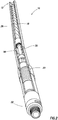
- the drilling motor 18 and bearing assembly 20 are representatively illustrated apart from the remainder of the drill string 12.
- the drilling motor 18 includes a power section 28 with a rotor contained in a stator, whereby fluid flow through the power section causes the rotor to rotate relative to the stator.
- the rotor is connected to an output shaft, which in this example includes a constant velocity connection 30 for transferring the rotor rotation via the bearing assembly 20 to a bit connector 32.
- the drilling motor 18 in this example may be similar in most other respects to a SPERRYDRILL(TM) positive displacement drilling motor marketed by Halliburton Energy Services, Inc. of Houston, Texas USA. However, other types of drilling motors (e.g., other positive displacement motors, turbine motors, etc.) may be used in other examples.
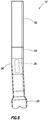
- the constant velocity connection 30 is representatively illustrated apart from the drilling motor 18 and the bearing assembly 20.
- the constant velocity connection 30 includes two ball-and-socket joints 34 positioned at opposite ends of a shaft 36, but other numbers of these components could be used in other examples.
- Each of the ball-and socket joints 34 includes a ball (e.g., a generally spherical structure) 38 received in a socket 40.
- the balls 38 are connected to the opposite ends of the shaft 36, by integrally forming the balls on the ends of the shaft, separately forming and then connecting the balls, etc.
- the scope of this disclosure is not limited to any particular way of constructing the various components of the connection 30.
- An insert 42 is received in an opening 44 formed laterally through each ball 38.
- the insert 42 and opening 44 are shaped, so that the insert can rotate about a lateral axis 48 perpendicular to the opening.
- the insert 42 may be in the form of a disk or a short cylinder.
- ball-and-socket joints 34 are offset 90 degrees rotationally from each other. This is to cancel out variations in rotational speed between the two joints 34.
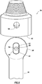
- FIG. 4 an example of one of the ball-and-socket joints 34 is representatively illustrated apart from the remainder of the constant velocity connection 30.
- a pin or journal 46 extends laterally through the insert 42, parallel to the opening 44 and extending along an axis 52 perpendicular to the axis 48.
- the socket 40 rotates with the insert 42 about the axis 48 relative to the ball 38, and also rotates with or about the journal 46 about the axis 52.
- the joint 34 can conveniently accommodate a planetary or epicyclic motion of the rotor in the drilling motor 18.
- connection 30 an exploded view of the ball-and-socket joint 34 is representatively illustrated. With this view, a method of constructing the connection 30 can be more easily understood.
- the insert 42 has been inserted into the opening 44, which extends along the axis 52.
- the insert 42 is free to rotate about the axis 48 in the ball 38 at this point.
- the ball 38 is then received in the socket 40.
- the socket 40 may be made up of multiple separate components, in order to provide for retaining the ball 38 in the socket, so that the socket can rotate relative to the ball.
- openings 54, 56 formed laterally through the insert 42 and socket 40, respectively, are aligned.
- the journal 46 is then installed in the aligned openings 54, 56 and secured (e.g., using snap rings, fasteners, press fitting, welding, etc.), so that the socket 40 now rotates about the axis 52.
- the socket 40 can rotate about each of the lateral axes 48, 52 relative to the ball 38.
- the socket 40 may rotate with or about the journal 46.
- the drilling motor 18 comprises a turbine-type motor.
- the drill string 12 of FIG. 6 has the bearing assembly 20 connected between the drilling motor 18 and the constant velocity connection 30.
- the constant velocity connection 30 is positioned in a bent housing 58.
- the constant velocity connection 30 is used in this example to transfer rotation and torque about a centerline of the drilling motor 18 to the drill bit 26, a centerline of which is not aligned with the drilling motor centerline.
- the constant velocity joint 30 could also be positioned in a bent housing 58 in the FIG. 2 example.
- the ball-and-socket joints 34 are robust, economical to manufacture and assemble, and accomplish a desired result of transmitting torque and rotation from an articulating rotor of the drilling motor 18 of FIG. 2 , and/or through the bent housing 58 of FIGS. 2 & 6 .
- a constant velocity connection 30 is described above for use in a drill string 12.
- the constant velocity connection 30 can include at least one ball-and-socket joint 34 and an insert 42 rotationally received in an opening 44 formed laterally through a ball 38 of the joint 34.
- the insert 42 may rotate about a first axis 48 relative to the ball 38.
- a socket 40 of the joint 34 can rotate about the first axis 48 relative to the ball 38.
- the first axis 48 is preferably perpendicular to the opening 44.
- the constant velocity connection 30 can also include a second axis 52 perpendicular to the first axis 48.
- the socket 40 can also rotate about the second axis 52 relative to the ball 38.
- the insert 42 may be generally disk shaped.
- the constant velocity connection 30 can also include a journal 46 which extends through the insert 42.
- the socket 40 may rotate about the journal 46.
- the socket 40 may also rotate about an axis 48 perpendicular to the journal 46.
- the constant velocity connection 30 can include two ball-and-socket joints 34 (although other numbers of joints may be used in other examples).
- the ball-and-socket joints 34 may be positioned at opposite respective ends of a shaft 36.
- the shaft 36 may transmit torque between a drilling motor 18 and a drill bit 26.
- the shaft 36 may transmit torque through a bent housing 58.
- a method of constructing a constant velocity connection 30 is also described above.
- the method can comprise: installing an insert 42 in an opening 44 formed in a ball 38 of at least one ball-and-socket joint 34 of the constant velocity connection 30; and allowing the insert 42 to rotate in the opening 44 about a first lateral axis 48.
- the opening 44 may extend laterally through the ball 38.
- the opening 44 can be perpendicular to the first axis 48.
- the method can include positioning a socket 40 of the ball-and-socket joint 34 over the ball 38.
- the positioning step may be performed after the insert 42 installing step.
- the method can include inserting a journal 46 through the insert 42 and at least partially into the socket 40.
- the socket 40 may rotate about a second axis 52 which extends through the journal 46.
- the method can include positioning the ball-and-socket joints 34 at opposite respective ends of a shaft 36.
- the method can include connecting the shaft 36 between a drilling motor 18 and a drill bit 26.
- the shaft 36 may transmit torque through a bent housing 58.
- the drill string 12 can include a drilling motor 18, a drill bit 26 and a constant velocity connection 30 connected between the drilling motor 18 and the drill bit 26, the constant velocity connection 30 including at least one ball-and-socket joint 34, and an insert 42 rotationally received in an opening 44 formed laterally through a ball 38 of the joint 34.
Landscapes
- Engineering & Computer Science (AREA)
- Life Sciences & Earth Sciences (AREA)
- Geology (AREA)
- Mining & Mineral Resources (AREA)
- Physics & Mathematics (AREA)
- Environmental & Geological Engineering (AREA)
- Fluid Mechanics (AREA)
- General Life Sciences & Earth Sciences (AREA)
- Geochemistry & Mineralogy (AREA)
- Mechanical Engineering (AREA)
- General Engineering & Computer Science (AREA)
- Earth Drilling (AREA)
Claims (14)
- Homokinetische Verbindung zur Verwendung in einem Bohrstrang, wobei die homokinetische Verbindung Folgendes umfasst:mindestens ein Kugelgelenk (38, 40);einen Einsatz (42), der in einer Öffnung (44), die seitlich durch eine Kugel des Gelenks gebildet ist, drehbar aufgenommen ist, undein Lagerzapfen (46), der sich durch den Einsatz erstreckt, und wobei sich eine Fassung des Gelenks um den Lagerzapfen dreht.
- Homokinetische Verbindung nach Anspruch 1, wobei sich der Einsatz um eine erste Achse (48) relativ zur Kugel dreht und wobei sich eine Fassung des Gelenks um die erste Achse relativ zur Kugel dreht.
- Homokinetische Verbindung nach Anspruch 2, wobei die erste Achse senkrecht zur Öffnung ist, und/oder
wobei die homokinetische Verbindung ferner eine zweite Achse (52) senkrecht zur ersten Achse umfasst, und wobei sich die Fassung auch um die zweite Achse relativ zur Kugel dreht. - Homokinetische Verbindung nach Anspruch 1, 2 oder 3, wobei der Einsatz im Wesentlichen scheibenförmig ist.
- Homokinetische Verbindung nach Anspruch 1, 2, 3 oder 4, wobei sich die Fassung auch um eine Achse senkrecht zum Lagerzapfen dreht.
- Homokinetische Verbindung nach einem der vorhergehenden Ansprüche, wobei das mindestens eine Kugelgelenk ein erstes und ein zweites Kugelgelenk umfasst, und wobei die Kugelgelenke an jeweils gegenüberliegenden Enden einer Welle positioniert sind.
- Homokinetische Verbindung nach Anspruch 6, wobei die Welle ein Drehmoment zwischen einem Bohrmotor (18) und einem Bohrmeißel (26) und/oder durch ein gekrümmtes Gehäuse (56) überträgt.
- Verfahren zum Konstruieren einer homokinetischen Verbindung, wobei das Verfahren Folgendes umfasst:Installieren eines Einsatzes (42) in einer Öffnung (44), die in einer Kugel von mindestens einem Kugelgelenk (38, 40) der homokinetischen Verbindung gebildet ist;Positionieren einer Fassung des Kugelgelenks über der Kugel;Einsetzen eines Lagerzapfens (46) durch den Einsatz und mindestens teilweise in die Fassung, undErmöglichen, dass sich der Einsatz in der Öffnung um eine erste seitliche Achse (48) dreht,wobei sich die Öffnung seitlich durch die Kugel erstreckt.
- Verfahren nach Anspruch 8, wobei die Öffnung senkrecht zur ersten Achse ist.
- Verfahren nach Anspruch 8, wobei das Positionieren nach dem Installieren durchgeführt wird, wobei wahlweise sich die Fassung um eine zweite Achse dreht, die sich durch den Lagerzapfen erstreckt.
- Verfahren nach Anspruch 8, wobei das mindestens eine Kugelgelenk ein erstes und ein zweites Kugelgelenk umfasst, und ferner Positionieren der Kugelgelenke an jeweils gegenüberliegenden Enden einer Welle umfasst.
- Verfahren nach Anspruch 11, ferner umfassend Verbinden der Welle zwischen einem Bohrmotor (18) und einem Bohrmeißel (26) und/oder
ferner umfassend, dass die Welle ein Drehmoment durch ein gekrümmtes Gehäuse (58) überträgt. - Bohrstrang, umfassend:einen Bohrmotor (18);einen Bohrmeißel (26); undeine zwischen dem Bohrmotor und dem Bohrmeißel verbundene homokinetische Verbindung nach einem der Ansprüche 1 bis 7.
- Bohrstrang nach Anspruch 13, wobei das mindestens eine Kugelgelenk ein erstes und ein zweites Kugelgelenk umfasst, und wobei die Kugelgelenke an jeweils gegenüberliegenden Enden einer Welle positioniert sind, und
wobei die Welle ein Drehmoment zwischen dem Bohrmotor und dem Bohrmeißel und/oder durch ein gekrümmtes Gehäuse überträgt.
Applications Claiming Priority (1)
| Application Number | Priority Date | Filing Date | Title |
|---|---|---|---|
| PCT/US2012/060539 WO2014062172A1 (en) | 2012-10-17 | 2012-10-17 | Drill string constant velocity connection |
Publications (3)
| Publication Number | Publication Date |
|---|---|
| EP2880247A1 EP2880247A1 (de) | 2015-06-10 |
| EP2880247A4 EP2880247A4 (de) | 2016-06-01 |
| EP2880247B1 true EP2880247B1 (de) | 2017-11-08 |
Family
ID=50488597
Family Applications (1)
| Application Number | Title | Priority Date | Filing Date |
|---|---|---|---|
| EP12886854.4A Not-in-force EP2880247B1 (de) | 2012-10-17 | 2012-10-17 | Homokinetische bohrstrangverbindung |
Country Status (8)
| Country | Link |
|---|---|
| US (1) | US10267098B2 (de) |
| EP (1) | EP2880247B1 (de) |
| CN (1) | CN104718342B (de) |
| AU (1) | AU2012392533B2 (de) |
| BR (1) | BR112015008403A2 (de) |
| CA (1) | CA2887769C (de) |
| RU (1) | RU2600248C1 (de) |
| WO (1) | WO2014062172A1 (de) |
Families Citing this family (6)
| Publication number | Priority date | Publication date | Assignee | Title |
|---|---|---|---|---|
| WO2016032868A1 (en) * | 2014-08-29 | 2016-03-03 | Ge Oil & Gas Esp, Inc. | Flexible joint connection |
| JP6846600B2 (ja) * | 2015-12-02 | 2021-03-24 | パナソニックIpマネジメント株式会社 | 球面軸受装置、および、スイッチ |
| WO2022170414A1 (en) | 2021-02-12 | 2022-08-18 | Drill Safe Systems Inc. | Drilling downhole regulating devices and related methods |
| GB2609656B (en) * | 2021-08-12 | 2024-07-03 | Deltatek Oil Tools Ltd | Offshore drilling apparatus and methods |
| WO2023081865A1 (en) * | 2021-11-05 | 2023-05-11 | Revolink, Llc | Flexible coupling |
| WO2023168510A1 (en) | 2022-03-08 | 2023-09-14 | David Dyck | Intakes and gas separators for downhole pumps, and related apparatuses and methods |
Family Cites Families (19)
| Publication number | Priority date | Publication date | Assignee | Title |
|---|---|---|---|---|
| US2694549A (en) | 1952-01-21 | 1954-11-16 | Eastman Oil Well Survey Co | Joint structure between flexible shafting and drill bit structure for drilling lateral bores |
| US3062024A (en) * | 1961-09-25 | 1962-11-06 | Bania Edward | Universal joint |
| US4145896A (en) * | 1977-06-24 | 1979-03-27 | United States Steel Corporation | Constant velocity joint |
| US4263788A (en) | 1979-03-23 | 1981-04-28 | Baker International Corporation | Universal joint apparatus having sliding plate construction for separating thrust and torque forces |
| CA1290952C (en) | 1986-10-11 | 1991-10-22 | Kenneth H. Wenzel | Downhole motor drive shaft universal joint assembly |
| US5094651A (en) | 1989-06-28 | 1992-03-10 | Cornay Paul J | Universal joint having hemispherical cup-shaped yoke and exterior, lubricating ring |
| US5288271A (en) * | 1992-04-13 | 1994-02-22 | Houston Engineers, Inc. | Constant velocity universal joint assembly for downhole motor |
| RU2037435C1 (ru) * | 1992-12-09 | 1995-06-19 | Герман Алексеевич Чикин | Полуосевая поворотная трансмиссия |
| US5569089A (en) * | 1993-10-28 | 1996-10-29 | Signorelli; Richard L. | Universal joint construction |
| US5467834A (en) | 1994-08-08 | 1995-11-21 | Maverick Tool Company | Method and apparatus for short radius drilling of curved boreholes |
| RU2156208C1 (ru) * | 1999-04-14 | 2000-09-20 | Любимов Александр Александрович | Колонка вертолета |
| US6742750B2 (en) * | 2001-10-12 | 2004-06-01 | William J. Burr | Adjustable leveling mount |
| CN2526495Y (zh) * | 2001-12-13 | 2002-12-18 | 天津市渤海石油机械有限公司 | 螺杆钻具球型万向轴总成 |
| GB2385869A (en) * | 2002-03-01 | 2003-09-03 | Halco Drilling Internat Ltd | Retaining broken drill in rock drilling apparatus |
| US7044240B2 (en) * | 2002-12-20 | 2006-05-16 | Mcneilly Keith | Torque absorber for downhole drill motor |
| BRPI0822535B1 (pt) * | 2008-04-30 | 2024-02-06 | Dreco Energy Services Ltd | Conjunto de eixo de acionamento, e, método para transferir uma carga de empuxo axial de um primeiro elemento rotativo alongado para um segundo elemento rotativo |
| US8033920B1 (en) * | 2009-04-10 | 2011-10-11 | Todd Benson | High torque, flexible, dual, constant velocity, ball joint assembly for mud motor used in directional well drilling |
| EP2341211A1 (de) * | 2009-12-30 | 2011-07-06 | Welltec A/S | Bohrlochleitwerkzeug |
| CA2769141C (en) * | 2011-03-08 | 2016-07-12 | Drilformance Technologies, Llc | Drilling apparatus |
-
2012
- 2012-10-17 CA CA2887769A patent/CA2887769C/en active Active
- 2012-10-17 EP EP12886854.4A patent/EP2880247B1/de not_active Not-in-force
- 2012-10-17 AU AU2012392533A patent/AU2012392533B2/en not_active Ceased
- 2012-10-17 CN CN201280076389.7A patent/CN104718342B/zh not_active Expired - Fee Related
- 2012-10-17 WO PCT/US2012/060539 patent/WO2014062172A1/en not_active Ceased
- 2012-10-17 BR BR112015008403A patent/BR112015008403A2/pt not_active IP Right Cessation
- 2012-10-17 RU RU2015118149/03A patent/RU2600248C1/ru not_active IP Right Cessation
- 2012-10-17 US US14/427,861 patent/US10267098B2/en active Active
Non-Patent Citations (1)
| Title |
|---|
| None * |
Also Published As
| Publication number | Publication date |
|---|---|
| CN104718342A (zh) | 2015-06-17 |
| RU2600248C1 (ru) | 2016-10-20 |
| EP2880247A4 (de) | 2016-06-01 |
| BR112015008403A2 (pt) | 2017-07-04 |
| US20150211308A1 (en) | 2015-07-30 |
| AU2012392533B2 (en) | 2015-07-23 |
| EP2880247A1 (de) | 2015-06-10 |
| AU2012392533A1 (en) | 2015-03-12 |
| CN104718342B (zh) | 2017-03-08 |
| CA2887769A1 (en) | 2014-04-24 |
| WO2014062172A1 (en) | 2014-04-24 |
| CA2887769C (en) | 2016-08-30 |
| US10267098B2 (en) | 2019-04-23 |
Similar Documents
| Publication | Publication Date | Title |
|---|---|---|
| US10895113B2 (en) | Drilling system, biasing mechanism and method for directionally drilling a borehole | |
| AU769053B2 (en) | Rotary steerable drilling tool | |
| US10081982B2 (en) | Torque transfer mechanism for downhole drilling tools | |
| EP2880247B1 (de) | Homokinetische bohrstrangverbindung | |
| CN104114805B (zh) | 定向钻井系统 | |
| US9556677B2 (en) | Directional drilling systems | |
| US10006249B2 (en) | Inverted wellbore drilling motor | |
| EP3201421B1 (de) | Gleichlaufgelenkvorrichtung, systeme und verfahren |
Legal Events
| Date | Code | Title | Description |
|---|---|---|---|
| PUAI | Public reference made under article 153(3) epc to a published international application that has entered the european phase |
Free format text: ORIGINAL CODE: 0009012 |
|
| 17P | Request for examination filed |
Effective date: 20150302 |
|
| AK | Designated contracting states |
Kind code of ref document: A1 Designated state(s): AL AT BE BG CH CY CZ DE DK EE ES FI FR GB GR HR HU IE IS IT LI LT LU LV MC MK MT NL NO PL PT RO RS SE SI SK SM TR |
|
| AX | Request for extension of the european patent |
Extension state: BA ME |
|
| DAX | Request for extension of the european patent (deleted) | ||
| REG | Reference to a national code |
Ref country code: DE Ref legal event code: R079 Ref document number: 602012039664 Country of ref document: DE Free format text: PREVIOUS MAIN CLASS: E21B0017020000 Ipc: E21B0007060000 |
|
| RA4 | Supplementary search report drawn up and despatched (corrected) |
Effective date: 20160503 |
|
| RIC1 | Information provided on ipc code assigned before grant |
Ipc: E21B 4/02 20060101ALI20160427BHEP Ipc: E21B 7/06 20060101AFI20160427BHEP Ipc: F16D 3/26 20060101ALI20160427BHEP Ipc: F16D 3/30 20060101ALI20160427BHEP |
|
| 17Q | First examination report despatched |
Effective date: 20170410 |
|
| GRAP | Despatch of communication of intention to grant a patent |
Free format text: ORIGINAL CODE: EPIDOSNIGR1 |
|
| INTG | Intention to grant announced |
Effective date: 20170710 |
|
| GRAS | Grant fee paid |
Free format text: ORIGINAL CODE: EPIDOSNIGR3 |
|
| GRAA | (expected) grant |
Free format text: ORIGINAL CODE: 0009210 |
|
| AK | Designated contracting states |
Kind code of ref document: B1 Designated state(s): AL AT BE BG CH CY CZ DE DK EE ES FI FR GB GR HR HU IE IS IT LI LT LU LV MC MK MT NL NO PL PT RO RS SE SI SK SM TR |
|
| REG | Reference to a national code |
Ref country code: GB Ref legal event code: FG4D |
|
| REG | Reference to a national code |
Ref country code: CH Ref legal event code: EP Ref country code: AT Ref legal event code: REF Ref document number: 944334 Country of ref document: AT Kind code of ref document: T Effective date: 20171115 |
|
| REG | Reference to a national code |
Ref country code: IE Ref legal event code: FG4D |
|
| REG | Reference to a national code |
Ref country code: DE Ref legal event code: R096 Ref document number: 602012039664 Country of ref document: DE |
|
| REG | Reference to a national code |
Ref country code: NL Ref legal event code: MP Effective date: 20171108 |
|
| REG | Reference to a national code |
Ref country code: LT Ref legal event code: MG4D |
|
| REG | Reference to a national code |
Ref country code: AT Ref legal event code: MK05 Ref document number: 944334 Country of ref document: AT Kind code of ref document: T Effective date: 20171108 |
|
| PG25 | Lapsed in a contracting state [announced via postgrant information from national office to epo] |
Ref country code: LT Free format text: LAPSE BECAUSE OF FAILURE TO SUBMIT A TRANSLATION OF THE DESCRIPTION OR TO PAY THE FEE WITHIN THE PRESCRIBED TIME-LIMIT Effective date: 20171108 Ref country code: NO Free format text: LAPSE BECAUSE OF FAILURE TO SUBMIT A TRANSLATION OF THE DESCRIPTION OR TO PAY THE FEE WITHIN THE PRESCRIBED TIME-LIMIT Effective date: 20180208 Ref country code: NL Free format text: LAPSE BECAUSE OF FAILURE TO SUBMIT A TRANSLATION OF THE DESCRIPTION OR TO PAY THE FEE WITHIN THE PRESCRIBED TIME-LIMIT Effective date: 20171108 Ref country code: FI Free format text: LAPSE BECAUSE OF FAILURE TO SUBMIT A TRANSLATION OF THE DESCRIPTION OR TO PAY THE FEE WITHIN THE PRESCRIBED TIME-LIMIT Effective date: 20171108 Ref country code: SE Free format text: LAPSE BECAUSE OF FAILURE TO SUBMIT A TRANSLATION OF THE DESCRIPTION OR TO PAY THE FEE WITHIN THE PRESCRIBED TIME-LIMIT Effective date: 20171108 Ref country code: ES Free format text: LAPSE BECAUSE OF FAILURE TO SUBMIT A TRANSLATION OF THE DESCRIPTION OR TO PAY THE FEE WITHIN THE PRESCRIBED TIME-LIMIT Effective date: 20171108 |
|
| PG25 | Lapsed in a contracting state [announced via postgrant information from national office to epo] |
Ref country code: IS Free format text: LAPSE BECAUSE OF FAILURE TO SUBMIT A TRANSLATION OF THE DESCRIPTION OR TO PAY THE FEE WITHIN THE PRESCRIBED TIME-LIMIT Effective date: 20180308 Ref country code: RS Free format text: LAPSE BECAUSE OF FAILURE TO SUBMIT A TRANSLATION OF THE DESCRIPTION OR TO PAY THE FEE WITHIN THE PRESCRIBED TIME-LIMIT Effective date: 20171108 Ref country code: GR Free format text: LAPSE BECAUSE OF FAILURE TO SUBMIT A TRANSLATION OF THE DESCRIPTION OR TO PAY THE FEE WITHIN THE PRESCRIBED TIME-LIMIT Effective date: 20180209 Ref country code: HR Free format text: LAPSE BECAUSE OF FAILURE TO SUBMIT A TRANSLATION OF THE DESCRIPTION OR TO PAY THE FEE WITHIN THE PRESCRIBED TIME-LIMIT Effective date: 20171108 Ref country code: BG Free format text: LAPSE BECAUSE OF FAILURE TO SUBMIT A TRANSLATION OF THE DESCRIPTION OR TO PAY THE FEE WITHIN THE PRESCRIBED TIME-LIMIT Effective date: 20180208 Ref country code: AT Free format text: LAPSE BECAUSE OF FAILURE TO SUBMIT A TRANSLATION OF THE DESCRIPTION OR TO PAY THE FEE WITHIN THE PRESCRIBED TIME-LIMIT Effective date: 20171108 Ref country code: LV Free format text: LAPSE BECAUSE OF FAILURE TO SUBMIT A TRANSLATION OF THE DESCRIPTION OR TO PAY THE FEE WITHIN THE PRESCRIBED TIME-LIMIT Effective date: 20171108 |
|
| PG25 | Lapsed in a contracting state [announced via postgrant information from national office to epo] |
Ref country code: DK Free format text: LAPSE BECAUSE OF FAILURE TO SUBMIT A TRANSLATION OF THE DESCRIPTION OR TO PAY THE FEE WITHIN THE PRESCRIBED TIME-LIMIT Effective date: 20171108 Ref country code: EE Free format text: LAPSE BECAUSE OF FAILURE TO SUBMIT A TRANSLATION OF THE DESCRIPTION OR TO PAY THE FEE WITHIN THE PRESCRIBED TIME-LIMIT Effective date: 20171108 Ref country code: CY Free format text: LAPSE BECAUSE OF FAILURE TO SUBMIT A TRANSLATION OF THE DESCRIPTION OR TO PAY THE FEE WITHIN THE PRESCRIBED TIME-LIMIT Effective date: 20171108 Ref country code: SK Free format text: LAPSE BECAUSE OF FAILURE TO SUBMIT A TRANSLATION OF THE DESCRIPTION OR TO PAY THE FEE WITHIN THE PRESCRIBED TIME-LIMIT Effective date: 20171108 Ref country code: CZ Free format text: LAPSE BECAUSE OF FAILURE TO SUBMIT A TRANSLATION OF THE DESCRIPTION OR TO PAY THE FEE WITHIN THE PRESCRIBED TIME-LIMIT Effective date: 20171108 |
|
| REG | Reference to a national code |
Ref country code: DE Ref legal event code: R097 Ref document number: 602012039664 Country of ref document: DE |
|
| PG25 | Lapsed in a contracting state [announced via postgrant information from national office to epo] |
Ref country code: RO Free format text: LAPSE BECAUSE OF FAILURE TO SUBMIT A TRANSLATION OF THE DESCRIPTION OR TO PAY THE FEE WITHIN THE PRESCRIBED TIME-LIMIT Effective date: 20171108 Ref country code: IT Free format text: LAPSE BECAUSE OF FAILURE TO SUBMIT A TRANSLATION OF THE DESCRIPTION OR TO PAY THE FEE WITHIN THE PRESCRIBED TIME-LIMIT Effective date: 20171108 Ref country code: SM Free format text: LAPSE BECAUSE OF FAILURE TO SUBMIT A TRANSLATION OF THE DESCRIPTION OR TO PAY THE FEE WITHIN THE PRESCRIBED TIME-LIMIT Effective date: 20171108 Ref country code: PL Free format text: LAPSE BECAUSE OF FAILURE TO SUBMIT A TRANSLATION OF THE DESCRIPTION OR TO PAY THE FEE WITHIN THE PRESCRIBED TIME-LIMIT Effective date: 20171108 |
|
| PLBE | No opposition filed within time limit |
Free format text: ORIGINAL CODE: 0009261 |
|
| STAA | Information on the status of an ep patent application or granted ep patent |
Free format text: STATUS: NO OPPOSITION FILED WITHIN TIME LIMIT |
|
| 26N | No opposition filed |
Effective date: 20180809 |
|
| PG25 | Lapsed in a contracting state [announced via postgrant information from national office to epo] |
Ref country code: SI Free format text: LAPSE BECAUSE OF FAILURE TO SUBMIT A TRANSLATION OF THE DESCRIPTION OR TO PAY THE FEE WITHIN THE PRESCRIBED TIME-LIMIT Effective date: 20171108 |
|
| REG | Reference to a national code |
Ref country code: DE Ref legal event code: R119 Ref document number: 602012039664 Country of ref document: DE |
|
| REG | Reference to a national code |
Ref country code: CH Ref legal event code: PL |
|
| GBPC | Gb: european patent ceased through non-payment of renewal fee |
Effective date: 20181017 |
|
| REG | Reference to a national code |
Ref country code: BE Ref legal event code: MM Effective date: 20181031 |
|
| PG25 | Lapsed in a contracting state [announced via postgrant information from national office to epo] |
Ref country code: LU Free format text: LAPSE BECAUSE OF NON-PAYMENT OF DUE FEES Effective date: 20181017 Ref country code: MC Free format text: LAPSE BECAUSE OF FAILURE TO SUBMIT A TRANSLATION OF THE DESCRIPTION OR TO PAY THE FEE WITHIN THE PRESCRIBED TIME-LIMIT Effective date: 20171108 |
|
| REG | Reference to a national code |
Ref country code: IE Ref legal event code: MM4A |
|
| PG25 | Lapsed in a contracting state [announced via postgrant information from national office to epo] |
Ref country code: DE Free format text: LAPSE BECAUSE OF NON-PAYMENT OF DUE FEES Effective date: 20190501 |
|
| PG25 | Lapsed in a contracting state [announced via postgrant information from national office to epo] |
Ref country code: LI Free format text: LAPSE BECAUSE OF NON-PAYMENT OF DUE FEES Effective date: 20181031 Ref country code: CH Free format text: LAPSE BECAUSE OF NON-PAYMENT OF DUE FEES Effective date: 20181031 Ref country code: FR Free format text: LAPSE BECAUSE OF NON-PAYMENT OF DUE FEES Effective date: 20181031 Ref country code: BE Free format text: LAPSE BECAUSE OF NON-PAYMENT OF DUE FEES Effective date: 20181031 |
|
| PG25 | Lapsed in a contracting state [announced via postgrant information from national office to epo] |
Ref country code: GB Free format text: LAPSE BECAUSE OF NON-PAYMENT OF DUE FEES Effective date: 20181017 Ref country code: IE Free format text: LAPSE BECAUSE OF NON-PAYMENT OF DUE FEES Effective date: 20181017 |
|
| PG25 | Lapsed in a contracting state [announced via postgrant information from national office to epo] |
Ref country code: MT Free format text: LAPSE BECAUSE OF NON-PAYMENT OF DUE FEES Effective date: 20181017 |
|
| PG25 | Lapsed in a contracting state [announced via postgrant information from national office to epo] |
Ref country code: TR Free format text: LAPSE BECAUSE OF FAILURE TO SUBMIT A TRANSLATION OF THE DESCRIPTION OR TO PAY THE FEE WITHIN THE PRESCRIBED TIME-LIMIT Effective date: 20171108 |
|
| PG25 | Lapsed in a contracting state [announced via postgrant information from national office to epo] |
Ref country code: PT Free format text: LAPSE BECAUSE OF FAILURE TO SUBMIT A TRANSLATION OF THE DESCRIPTION OR TO PAY THE FEE WITHIN THE PRESCRIBED TIME-LIMIT Effective date: 20171108 |
|
| PG25 | Lapsed in a contracting state [announced via postgrant information from national office to epo] |
Ref country code: HU Free format text: LAPSE BECAUSE OF FAILURE TO SUBMIT A TRANSLATION OF THE DESCRIPTION OR TO PAY THE FEE WITHIN THE PRESCRIBED TIME-LIMIT; INVALID AB INITIO Effective date: 20121017 Ref country code: MK Free format text: LAPSE BECAUSE OF NON-PAYMENT OF DUE FEES Effective date: 20171108 |
|
| PG25 | Lapsed in a contracting state [announced via postgrant information from national office to epo] |
Ref country code: AL Free format text: LAPSE BECAUSE OF FAILURE TO SUBMIT A TRANSLATION OF THE DESCRIPTION OR TO PAY THE FEE WITHIN THE PRESCRIBED TIME-LIMIT Effective date: 20171108 |