EP2880312B1 - Pompe électromagnétique - Google Patents
Pompe électromagnétique Download PDFInfo
- Publication number
- EP2880312B1 EP2880312B1 EP13734331.5A EP13734331A EP2880312B1 EP 2880312 B1 EP2880312 B1 EP 2880312B1 EP 13734331 A EP13734331 A EP 13734331A EP 2880312 B1 EP2880312 B1 EP 2880312B1
- Authority
- EP
- European Patent Office
- Prior art keywords
- armature
- core part
- air gap
- receiving portion
- pump
- Prior art date
- Legal status (The legal status is an assumption and is not a legal conclusion. Google has not performed a legal analysis and makes no representation as to the accuracy of the status listed.)
- Not-in-force
Links
- 238000003780 insertion Methods 0.000 claims description 138
- 230000037431 insertion Effects 0.000 claims description 138
- 230000005291 magnetic effect Effects 0.000 claims description 72
- 230000005294 ferromagnetic effect Effects 0.000 claims description 64
- 238000005086 pumping Methods 0.000 claims description 9
- 239000012530 fluid Substances 0.000 description 12
- 230000002093 peripheral effect Effects 0.000 description 8
- 238000013461 design Methods 0.000 description 7
- 230000000295 complement effect Effects 0.000 description 5
- 230000008859 change Effects 0.000 description 4
- 230000007423 decrease Effects 0.000 description 4
- 238000011161 development Methods 0.000 description 4
- 230000000694 effects Effects 0.000 description 4
- 239000000463 material Substances 0.000 description 4
- 238000000418 atomic force spectrum Methods 0.000 description 3
- 238000005516 engineering process Methods 0.000 description 3
- 230000005284 excitation Effects 0.000 description 3
- 230000002349 favourable effect Effects 0.000 description 3
- 230000004907 flux Effects 0.000 description 3
- 238000004519 manufacturing process Methods 0.000 description 3
- 238000010276 construction Methods 0.000 description 2
- 230000001419 dependent effect Effects 0.000 description 2
- 239000012811 non-conductive material Substances 0.000 description 2
- 239000004033 plastic Substances 0.000 description 2
- 230000009467 reduction Effects 0.000 description 2
- 230000004044 response Effects 0.000 description 2
- 239000004809 Teflon Substances 0.000 description 1
- 229920006362 Teflon® Polymers 0.000 description 1
- 230000001133 acceleration Effects 0.000 description 1
- 230000009471 action Effects 0.000 description 1
- 230000006978 adaptation Effects 0.000 description 1
- 238000013459 approach Methods 0.000 description 1
- 230000002238 attenuated effect Effects 0.000 description 1
- 230000015572 biosynthetic process Effects 0.000 description 1
- 239000004020 conductor Substances 0.000 description 1
- 230000036461 convulsion Effects 0.000 description 1
- 230000006735 deficit Effects 0.000 description 1
- 238000002347 injection Methods 0.000 description 1
- 239000007924 injection Substances 0.000 description 1
- 239000007788 liquid Substances 0.000 description 1
- 238000000034 method Methods 0.000 description 1
- 239000002245 particle Substances 0.000 description 1
- 230000000149 penetrating effect Effects 0.000 description 1
- -1 polytetrafluoroethylene Polymers 0.000 description 1
- 229920001343 polytetrafluoroethylene Polymers 0.000 description 1
- 239000004810 polytetrafluoroethylene Substances 0.000 description 1
- 230000008569 process Effects 0.000 description 1
- 230000000644 propagated effect Effects 0.000 description 1
- 230000000630 rising effect Effects 0.000 description 1
- 238000007789 sealing Methods 0.000 description 1
- 239000000243 solution Substances 0.000 description 1
- 125000006850 spacer group Chemical group 0.000 description 1
Images



Classifications
-
- F—MECHANICAL ENGINEERING; LIGHTING; HEATING; WEAPONS; BLASTING
- F04—POSITIVE - DISPLACEMENT MACHINES FOR LIQUIDS; PUMPS FOR LIQUIDS OR ELASTIC FLUIDS
- F04B—POSITIVE-DISPLACEMENT MACHINES FOR LIQUIDS; PUMPS
- F04B35/00—Piston pumps specially adapted for elastic fluids and characterised by the driving means to their working members, or by combination with, or adaptation to, specific driving engines or motors, not otherwise provided for
- F04B35/04—Piston pumps specially adapted for elastic fluids and characterised by the driving means to their working members, or by combination with, or adaptation to, specific driving engines or motors, not otherwise provided for the means being electric
-
- F—MECHANICAL ENGINEERING; LIGHTING; HEATING; WEAPONS; BLASTING
- F04—POSITIVE - DISPLACEMENT MACHINES FOR LIQUIDS; PUMPS FOR LIQUIDS OR ELASTIC FLUIDS
- F04B—POSITIVE-DISPLACEMENT MACHINES FOR LIQUIDS; PUMPS
- F04B17/00—Pumps characterised by combination with, or adaptation to, specific driving engines or motors
- F04B17/03—Pumps characterised by combination with, or adaptation to, specific driving engines or motors driven by electric motors
- F04B17/04—Pumps characterised by combination with, or adaptation to, specific driving engines or motors driven by electric motors using solenoids
- F04B17/048—Pumps characterised by combination with, or adaptation to, specific driving engines or motors driven by electric motors using solenoids the fluid flowing around the moving part of the motor
Definitions
- the invention relates to an electromagnetic pump.
- Electromagnetic pumps known in practice have a coil extending along a longitudinal axis, wherein the coil is in each case partially penetrated by a first ferromagnetic core part and a second ferromagnetic core part.
- the ferromagnetic core parts are spaced apart from one another in the interior of the coil, wherein an armature that at least partially passes through the two core parts is axially displaced axially when the coil is excited by the resulting magnetic field.
- an axial primary air gap is arranged between the first ferromagnetic core part and the armature
- a radial secondary air gap is arranged between the second ferromagnetic core part and the armature, wherein an insertion section of the armature guided in the second core part is cylindrical.
- the cylindrical insertion section is received in a likewise cylindrical receiving portion of the second core part, wherein in the region of the first core part facing end face of the receiving portion, an insertion of the anchor facilitating chamfer can be provided.
- a disadvantage is limited by the cylindrical configuration of the insertion section, the structural design of the magnetic circuit but essentially to the first ferromagnetic core part and the first ferromagnetic core part facing anchor head of the anchor.
- the movement of the armature towards the end of the energization of the coil must be controlled by a sophisticated electronics for braking in order to achieve a stroke-force characteristic that deviates from a substantially exponentially increasing stroke-force characteristic.
- DE 10 2008 058 046 A1 describes in one embodiment, an electromagnetic reciprocating pump with a coil and a first and a second partially arranged in the coil ferromagnetic Core part.
- a ferromagnetic armature is slidably received in a support sleeve made of a magnetically non-conductive material, wherein the support sleeve is provided in a receiving portion of the second core part facing the first core part.
- a primary air gap is arranged between the armature and the first core part, and a secondary air gap is arranged between an insertion section of the armature and a receiving section of the second core part.
- the magnet armature has at a first core part facing the end of a recess in which a first spring is received, which is supported at its end remote from the armature to the first core part.
- a support element is provided, on which a first end of a second spring is supported.
- a second end of the second spring is supported on a recess of a dosing cylinder received in the second core part.
- a magnetic force between the armature and the first core part is greater than a magnetic force between the armature and the second core part.
- the insertion section and the receiving section have no conical sections through which a stroke-force characteristic changing over the stroke can be realized.
- additional measures such as the provision of control electronics, must be taken.
- US 2009/0 200 499 A1 shows an electromagnetic linear drive for a pump with a coil which is partially enclosed by a first ferromagnetic core part and a second ferromagnetic core part.
- a ferromagnetic armature having yoke sections and magnet sections is slidably received in a central area of the first core part and the second core part.
- the armature has a first guide section and a second guide section with which the armature is guided in a first centering disk and a second centering disk.
- an air gap is formed between the An armature and the first core part and between the armature and the second core part.
- no primary air gap is arranged between the armature and the first core part.
- no insertion section is provided with at least one conical section which has a different opening angle than the frusto-conical contour of the front region of the ferromagnetic armature.
- DE 11 01 960 B describes an electromagnetic pump comprising a coil which is enclosed by a ferromagnetic housing.
- the housing forms a cylindrical pumping space, in which a ferromagnetic core part is accommodated.
- a ferromagnetic armature is accommodated axially displaceably in the pump space, wherein an air gap is formed between the armature and the core part.
- the pumping space is delimited at an end opposite the core part by a sealing flange made of a non-magnetically conductive material.
- the armature is biased against the closure flange by means of a spring, which is supported on the core part and the armature, wherein an abutment is formed on the armature by a radially projecting insertion section of the armature, with which the armature is guided in the pump chamber.
- the armature Upon energization of the coil, the armature displaces in response to a magnetic force against a spring force in the direction of the core part. After de-energizing the coil, the armature returns to a preloaded initial position.
- the anchor may also have a conical shape. An at least partially disposed in the coil second core part is not provided, as no at least partially disposed in the coil second core part.
- a radial, secondary air gap between the insertion portion of the armature and the receiving portion of the second core member is absent, so that a magnetic force between the armature and the first core member at a closing operation of the first air gap is greater than a magnetic force between the armature and the second core member.
- DD 128 346 A1 shows an electromagnetic drive with a coil and a first ferromagnetic core part.
- a ferromagnetic armature In a receiving portion of a second ferromagnetic core part, a ferromagnetic armature is slidably received with an insertion. Between the armature and the first core part and between the armature and the second magnetic core part, a primary and a secondary air gap are arranged.
- a magnetic force between the armature and the first core part is greater than between the armature and the second core part, whereby the armature is displaced in the direction of the first core part and the primary air gap is closed.
- the insertion section of the armature has a stepped contour.
- a ferromagnetic armature with a first core part facing the front region with a stroke direction tapering frustoconical contour is not shown.
- a front portion of the armature projecting radially beyond an end face of the receiving portion of the second core part facing the first core part, and an insertion portion having at least one tapered portion having an opening angle other than the frusto-conical contour of the front portion of the ferromagnetic armature are not shown ,
- DE 696 07 230 T2 describes an electromagnetic pump comprising a coil and a first ferromagnetic core part. Opposite the first core part, a second ferromagnetic core part is arranged, wherein the first core part and the second core part form a low-pressure chamber of the pump. In the low pressure chamber, a ferromagnetic armature is slidably received. Between the armature and the first core part, a primary air gap and between the armature and the second core part, a secondary air gap is arranged. The armature has a receiving portion on which a first end of a spring is supported. A second end of the spring is supported on an extension of a low-pressure chamber limiting Housing part of the pump.
- the armature is biased against a spacer of the second core part.
- a magnetic force between the armature and the first core part is greater than between the armature and the second core part, whereby the armature is displaced against a spring force in the direction of the first core part. This reduces the primary air gap between the armature and the first core part.
- the armature In a de-energized state of the coil, the armature returns due to the spring force back into an initial position.
- the contour of the armature has cylindrical sections with different diameters and conical sections.
- a ferromagnetic armature having a front region facing the first core part with a frustoconical contour tapering in the stroke direction or a front region of the armature projecting radially over an end face of the receiving section of the second core part facing the first core part is not shown.
- no insertion section is provided with at least one conical section which has an opening angle deviating from the frusto-conical contour of the front area of the ferromagnetic armature.
- US 2 006 592 A shows an electromagnetic pump, comprising a first coil and a second coil, which are arranged axially spaced apart in a pump housing.
- the first coil and the second coil are radially bounded on the inside by a support sleeve of a magnetically non-conductive material, which forms a pumping chamber of the pump.
- the pumping chamber is limited in the axial direction at one end by a first ferromagnetic core part, which is partially enclosed by the second coil.
- the pump chamber is bounded in the axial direction by a second ferromagnetic core part, which is partially enclosed by the first coil.
- a ferromagnetic armature is received axially displaceable.
- the armature Upon energization of the first coil, the armature displaces due to a magnetic force in the direction of the first core part, wherein the primary air gap is closed.
- the armature When the first coil is de-energized and the second coil is energized, the armature is displaced in the direction due to a magnetic force acting in the opposite direction of the second core part, wherein the secondary air gap is closed.
- the armature has tapered insertion portions at first and second ends that are aligned with tapered receiving portions in the first core portion and the second core portion such that the anchor is insertable into the first core portion and the second core portion.
- An electromagnetic pump with exactly one coil is not shown.
- no radial, secondary air gap is arranged between the insertion section of the armature and the receiving section of the second core section facing the longitudinal axis.
- An insertion portion having at least one tapered portion having an opening angle other than the frusto-conical contour of the front portion of the ferromagnetic anchor is also not shown.
- FR 2 428 343 A1 describes an electromagnetic linear drive with a coil arranged in a housing.
- the coil is clamped between a first housing half and a second housing half and projects into an actuator space.
- a U-shaped ferromagnetic core part is arranged around the coil.
- a ferromagnetic armature passes through the coil and the core part and is displaceably received in the first housing half by means of a first cylindrical guide section and in the second housing half by means of a second cylindrical guide section.
- the second guide portion is enclosed by a spring, which is supported at one end to the second housing half and the other end to a spring plate fixed on the armature, so that the armature is biased relative to the second housing half.
- the armature Upon energization of the coil, the armature displaces against a bias in the direction of the second housing half as a result of a magnetic force. In a de-energized state of the coil, the armature returns to an initial position due to a return action of the spring.
- the armature is conically formed along a portion located in the core portion and the coil.
- an electromagnetic pump comprises a coil having a longitudinal axis, a first ferromagnetic core part arranged at least partially in the coil, and a second ferromagnetic core part at least partially disposed in the coil and a ferromagnetic armature.
- a magnetic field is generated which extends over the two core parts and the armature.
- the magnetic field has to bridge a primary air gap between the armature and the first core part and a secondary air gap between an insertion section of the armature and a longitudinal axis facing receiving portion of the second core part, where a force acting between the armature and the first core part magnetic force in a closing operation is always greater than a magnetic force between the armature and the second core part.
- At least one of insertion section of the armature and receiving section of the second core part have a shape deviating from a cylindrical shape.
- the deviating contour is preferably itself cylindrical again, e.g. designed as a radial ring or radial groove.
- the stroke-force characteristic or the stroke-force curve at the beginning of a stroke movement as high a force as possible, whereas in an average stroke range only an average force is generated, which decreases significantly to the stroke end.
- the magnetic resistance at the secondary air gap is highly stroke-dependent and, in comparison to the primary resistance, becomes larger than in known lifting magnets.
- the deviating contour can be a lifting force of ferromagnetic armature are tuned to a respective movement section of the armature.
- the electromagnetic pump makes it possible to influence by geometric changes of the secondary air gap limiting pump parts on the obtained by energizing the coil feed of the armature force, in particular to increase or decrease, and to change these in particular over the stroke of the armature. So it is particularly possible to influence by a change in the secondary air gap in the region of the last part of the stroke of the armature, the force so that the armature is not displaced with maximum force, but experiences a braking and thus the material of the pump less wear subject. As a result, a complex electronic Abregelung the energization of the coil can be avoided and a simple and inexpensive control can be provided. Furthermore, the life of the electromagnetic pump is extended and the mechanical stress of the corresponding parts of the pump is reduced.
- At least one of insertion section of the armature and receiving portion of the second core part over a range of at least one sixth, preferably a quarter of a maximum axial extent of the secondary air gap has a deviating from the cylindrical shape contour.
- the region in which the contour of the insertion section or of the receiving section deviating from the cylindrical contour is provided is provided at a distance from the end face of the second core part facing the first core part.
- the deviating from the cylindrical contour contour may be formed by a step in the region of the receiving portion or the insertion, wherein a plurality of stages may be provided.
- the cylindrical contour of the circumference of the insertion deviating area itself again has a cylindrical peripheral portion, the distance from the axis of the armature but deviates from that of the circumference of the insertion.
- the corresponding region consists of several sub-stages, wherein these are preferably formed rotationally symmetrical.
- a constriction may be provided on an end of the receiving region of the second core part facing the first core part.
- a constriction may also be provided on an end of the receiving region of the second core part facing away from the first core part.
- the magnetoresistance in the end region of the lifting movement of the armature is advantageously increased, so that advantageous braking of the lifting movement takes place before the armature strikes the first core part.
- both the insertion section and the receiving section are equipped with a deviating from the cylindrical contour area, which preferably, but not necessarily, partially superimposed, so that due to the stroke of the actuator, the configuration of the secondary air gap at least over a sixth, preferably a quarter the maximum extension of the secondary air gap, which it assumes in the de-energized state of the coil, is influenced.
- a region projecting from the circumference of the insertion section is provided on the insertion section in such a way that it is arranged with a likewise recessed region on the receiving section in such a way that the insertion section and the receiving section reach a certain stroke of the actuator in FIG Covering and thus particularly affect this phase of the stroke.
- the same can be provided for the initial phase of the stroke.
- the recessed region of the receiving section particularly preferably forms a constriction at an end of the receiving section facing the first core part and recessed portion of the insertion section has a flange on an end of the armature facing away from the first core part. It comes advantageously to a strong reduction of the magnetic resistance in an end region of the lifting movement of the armature.
- At least one of insertion section of the armature and receiving section of the second core part over a range of at least one third of a maximum axial extent of the secondary air gap has a different contour from the cylindrical contour.
- that region of the maximum axial extension of the secondary air gap, over which the insertion section and / or the receiving section deviate from a cylindrical contour makes up more than half, in particular preferably more than three quarters of the corresponding extent, so that the adjusting effect is particularly pronounced in the relocation of the anchor.
- both the insertion section and the receiving section deviate from the cylindrical shape, in order thereby to achieve a particularly effective influencing of the secondary air gap.
- the deviating contour extends over a plurality of and / or larger areas, wherein particularly preferably at least two contour sections deviating from the cylindrical contour and spaced apart from each other are provided.
- an electromagnetic pump is advantageously provided, which has an improved magnetic flux line at exactly definable times of movement of the armature.
- At least one of insertion section of the armature and receiving portion of the second core part over a range of at least one sixth, preferably one quarter of a maximum extent of the secondary air gap is conical.
- a parabolic, elliptical or hyperbolic formation of the Insertion section of the armature or the receiving portion of the second core part may be provided.
- the correspondingly formed insertion section or receiving section extends over more than half of the axial extent of the corresponding parts, in particular over the entire axial extent in the region of the secondary air gap.
- This can be manufactured easily produced by the receiving section as a whole, but in any case over the area that receives the insertion of the armature, a slightly conical configuration undergoes, however, deviates from the cylindrical shape only a few degrees.
- the insertion section of the armature is formed, so that when the coil is de-energized the outer cone of the insertion section has the greatest proximity to the inner cone of the receiving section.
- the width of the secondary air gap increases, and accordingly, the force is reduced with increasing stroke of the armature.
- the portions which are cone-shaped may also be spaced apart from each other with cylindrical steps, or may be provided only in areas of the circumference of the portion.
- a third preferred embodiment of the electromagnetic pump is provided that exactly one of insertion section of the armature and receiving portion of the second core part has a gradation with widened secondary air gap.
- the insertion section of the armature is designed accordingly, this can be accomplished in a simple manner in terms of production technology, and a correspondingly machined armature can be inserted into existing core parts.
- a different characteristic can be set, both with respect to the stroke and the intensity of the change in force, so that several different anchors in the manner of a kit adapted respectively to the needs of the specific pump can be used in the same core part. The solution achieved can be easily realized in terms of manufacturing technology and can thus be produced cost-effectively.
- a radially projecting from the insertion of the armature projection has a first core part facing surface.
- the projection projecting radially in front of the insertion section of the anchor is expediently of rotationally symmetrical design so that it encloses the insertion section in the manner of a ring.
- different cross sections of the projection are possible, for example as a trapezoid, triangle, rectangle, dovetail, large-U or the like.
- more than one projection is provided, for example with a cross-section shaped as a large-W or a plurality of consecutive projections with a different cross-section.
- the at least one projection has a surface which faces the first core part, that is to say which has at least one component which exhibits energization in the stroke direction of the armature.
- This surface is in a particularly simple realization in a plane normal to the stroke direction, but it is also possible that this surface has a slope in the manner of a truncated cone.
- the projection extends only over a length of the insertion of less than a sixth of its extension and is provided at a position of the peripheral portion, which is still at maximum stroke of the first core part facing end side of the receiving portion axially spaced.
- the receiving portion of the second core part has an inner projection facing the longitudinal axis. This increases the magnetic flux density in the pump, so that a changed magnetic force is exerted on the armature.
- the inner projection expediently has a surface facing the first core part, and in the case of a symmetrical construction also a surface facing away from the first core part.
- both the insertion section of the anchor has a protruding projection and the receiving section of the second core part has an internal projection
- magnetic components of the two parts which approach or leave each other via the stroke of the anchor can be used to obtain force components which transmit the force of the anchor increase or decrease the stroke.
- an axial force component becomes effective in the region of the secondary air gap, which can be easily realized by selecting the position of the projection or the inner projection.
- the appropriate arrangement of projection and inner projection that is, whether the projection is displaced in the direction of the inner projection or from the inner projection, resulting in the respectively desired force components. It is understood that overlapping effects are possible in providing more than one projection and / or more than one inner projection. Conveniently, the inner projection and the projection partially overlap in axial projection.
- the effective axial surfaces of the axially opposite portions of the two projections are significantly smaller than the axially opposite surfaces of the armature cone and armature counterpart;
- the ratio of the areas is less than 1:10, more preferably less than 1:25.
- the maximum outer diameter of the insertion section of the armature is smaller than the minimum inner diameter of the receiving section of the second core section.
- the contour deviating from a cylindrical shape has a plurality of steps.
- the plurality may be provided in the insertion section of the armature and / or in the receiving section of the second core part, resulting in individually adjustable or modifiable force profiles over the stroke.
- the insertion section of the armature is preferably moved out of the receiving section of the second core part completely. This increases the magnetic resistance, which advantageously achieves a deceleration of the movement of the armature to one end of the lifting movement, thereby advantageously attenuating the strength of the impact of the armature against the first core part towards the end of the lifting movement.
- a support sleeve made of plastic or the like.
- the support sleeve may be provided for lining a recessed groove in the armature or receiving portion.
- the support sleeve is suitably selected from a material which is not magnetically conductive and thus magnetically equates to an air gap substantially.
- the support sleeve can also line a deviating from the cylindrical shape portion of the receiving portion and extend the receiving portion.
- a support sleeve made of polytetrafluoroethylene be attached to the end face of the receiving portion.
- the front region of the armature projects radially beyond an end face of the receiving portion of the second core part facing the first core part.
- the front portion of the armature has a reduced outer diameter, which does not protrude radially beyond the first core part facing end side of the receiving portion.
- the executed stroke of the armature can be at least approximately linearized over the current, which can be adjusted particularly favorable and partial strokes, for example in a pressure-regulating pump.
- a pressure-regulating pump is the Spring force and possibly the effective piston surfaces of the armature tuned so that the armature is not reset in a jerk against the stroke direction and a certain volume is ejected, but a pressure in the outlet is set.
- an electromagnetic pump is characterized in that the conical portion of the insertion of the armature tapers against the tapered in the stroke direction frustoconical contour of the front portion of the armature, whereby an axial, in particular against the stroke direction acting component of the actuator displacing magnetic force is achieved ,
- the conical section of the insertion section of the armature extends partially outside the receiving section.
- the tapered conical section of the insertion section of the armature which tapers counter to the stroke direction, is steeper than the frustoconical contour of the front section of the armature which tapers in the stroke direction.
- both parts can be simply plugged into each other.
- the electromagnetic pump is preferably selected from the group comprising reciprocating pump, diaphragm pump, pressure-regulating pump and metering pump.
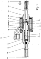
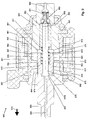
- Fig. 1 shows an electromagnetic pump 100 designed as a metering pump, with a housing 101, an electromagnetic coil 102 arranged in the housing 101, a first ferromagnetic core part 103 and a second ferromagnetic core part 104.
- the electromagnetic coil 102 is wound on a bobbin 105 and is partially penetrated in its inner region by the first ferromagnetic core part 103 and the second ferromagnetic core part 104, respectively.
- the two ferromagnetic core parts 103, 104 are spaced apart from one another by a pump chamber 107 defining a distance 106, wherein the first ferromagnetic core part 103 has a supply line 108 and the second ferromagnetic core part 104 has a discharge line 109 for a fluid to be conveyed.
- a movable, ferromagnetic armature 110 is arranged, which armature 110 is biased by a arranged between the armature 110 and the first core member 103 spring 111 in a conveying direction 112 of the electromagnetic pump 100.
- the armature 110 has essentially a hollow cylindrical shape and is penetrated by a piston rod 113 in its entire longitudinal extent, wherein the piston rod 113 protrudes beyond the armature 110 in the conveying direction 112 and thereby passes through a metering cylinder 114.
- the armature 110 In its first region 115 facing the first core part 103, the armature 110 has a frustoconical contour tapering in the stroke direction.
- the first core part 103 has a conical counterpart 119 facing the armature 110 and complementary to the front region 115 of the armature 110, wherein a region between the armature 110 and the conical armature counterpart 119 is referred to as a primary air gap.
- the front portion 115 protrudes into the axial distance between the two core parts 103, 104.
- the armature 110 extends with an end facing away from the first core part 103, formed as an insertion portion 117 in a receiving portion 118 of the second core portion 104, wherein the front portion 115 of the armature 110 projects radially beyond a first core part 103 facing end side of the receiving portion 118 of the second core part 104.
- An area between the insertion portion 117 of the armature 110 and the receiving portion 118 of the second core portion 104 is referred to as a secondary air gap.
- the region between the front region 115 of the armature 110 and the counterpart 119 of the first core part 103 defines a primary air gap 151, the axial extent of which is maximized in the case of a deenergized coil 102.
- the peripheral surface of the insertion portion 117 of the armature 110 and the longitudinal axis of the coil 102 facing receiving portion 118 of the second core member 104 define in the region in which they are opposed, a substantially radial, secondary air gap 152.
- the longitudinal axis is in Fig. 1 denoted by 153.
- the magnetic force between the armature 110 and the first core member 103 is greater than the magnetic force between the armature 110 and the second core member 104 due to the resulting magnetic field at a closing operation of the first air gap 151.
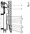
- Fig. 2 shows an enlarged section of the pump 100 according to Fig. 1 from which, in particular, the concrete configuration of the outer contour of the insertion portion 117 and the receiving portion 118 results.
- the insertion portion 117 of the armature 110 in the region of an otherwise cylindrical peripheral surface on an annular outer projection 120 which extends over the entire radial circumference of the insertion portion 117.
- This radially projecting outer projection 120 also represents the maximum outer diameter of the insertion section 117 and has a radially to outwardly facing, to the peripheral surface of the Ein Sinceabrabsterrorisms 117 concentric annular surface 120a, which is connected via a first, facing in the stroke direction and thus the first core portion 103 facing surface 120b with the remaining insertion portion 117, and the second core 103 facing away from the one Surface 120c is connected to a rear portion of the insertion portion 117, so as to give a cross-section in approximately trapezoidal profile of the outer projection 120.
- the surface 120b facing the first core part 103 and the surface 120c of the outer projection 120 facing away from the first core part 103 can also be configured differently, in particular perpendicular to the longitudinal axis 153 or the main axis of the insertion section 117, or vice versa may be configured trapezoidal, so that an approximately dovetailed cross-section of the outer projection 120 is formed.
- the projection may also have a rounded contour.
- the receiving portion 118 of the second core part 104 has an inner projection 121 offset from the position of the outer projection 120 in the direction of the first core part 103, which is directed radially in the direction of the longitudinal axis 153 of the armature 110 and has a completely closed annular course.
- the outer projection 120 and the inner projection 121 are arranged spaced apart in the longitudinal direction, wherein the inner projection 121 has a concentric with the otherwise cylindrical shape of the insertion portion 117 extending inner annular surface 121 a, the one 121a facing the first core portion 103 surface with the inner ring surface 121a is connected via a second, the first core portion 103 facing away from the surface 121 c with the receiving portion 118 and facing the first surface 120 b of the outer projection 120.
- the inner projection 121 and the outer projection 120 partially overlap in the projection, so that upon excitation of the coil 102 and the stroke of the armature 110 caused thereby, the outer projection 120 comes closer to the inner projection 121. This will the force of the armature 110 is increased by the resulting axial component in the region of the secondary air gap 152, so that in an end phase of the stroke of the armature 110, the force acting on the armature 110 is increased. Conveniently, even at the maximum stroke of the armature 110, the inner projection 120 and the outer projection 121 are still spaced from each other so that contact does not occur.
- the outer projection 121 in the stroke direction of the actuator 110 upon energization of the coil 102 may be disposed behind the inner projection 120, so that then the first core portion 103 facing surface 121 b of the first core portion 103 facing away from the surface 120c , It is also possible that a plurality of inner projections 120 and / or a plurality of outer projections 121 are provided, in which case an inner projection and / or an outer projection may also be adjacent to each of two facing surfaces of adjacent projections.
- the inner projection 120 and the outer projection 121 may be formed so that they are guided past each other, so that the insertion portion 117 of the armature 110 is inserted into the receiving portion 118 of the second core member 104 from the direction of the first core member 103.
- at least one of the inner projection and the outer projection is perforated, so that the respective other can be guided past this.
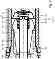
- Fig. 3 shows an alternative embodiment of the secondary air gap, wherein the same or structurally comparable parts of the electromagnetic pump have the same reference numerals as in the embodiment according to FIG Fig. 1 and 2 and therefore only the differences are highlighted.
- the insertion section 217 of the armature 210 has a circumferential surface 222 tapering in the conveying direction 112, the conical shape extending over almost the entire extent of the insertion section 217.
- the cone angle, in Fig. 3 is shown, for reasons of clarity, larger than would be the case in the practical construction.
- the receiving portion 218 has a hollow cylindrical inner peripheral surface 223, so that when the coil 102 is de-energized, the thickness of the secondary air gap 252 between the insertion portion 217 and the receiving portion 218 near the end face of the receiving portion 218 is minimal, and close to the end of the receiving portion facing away from the first core portion 103 218 is maximum.
- the third embodiment according to Fig. 4 differs from the previous embodiment only in the configuration of the insertion of the armature, so that the same reference numerals as in the previous embodiment are otherwise used for the same or structurally comparable parts.
- the armature 310 has an insertion section 317, which is provided with a step 330 which is provided circumferentially around the lateral surface of the insertion section 317, so that the secondary air gap 352 has a lower thickness in an end face of the receiving section 218 facing the first core section 103
- the step 330 may also be arranged so that the recessed portion is located near the front portion 115 of the core portion 310, and also more than a step, such as a cascade of small steps over parts of the extension of the insertion section 317 or may be provided over the entire insertion section 317, wherein expediently at least a quarter of the maximum extent of the secondary air gap 352 is formed differently from the remaining circumference of the insertion.
- the magnetic resistance of the rear portion of the insertion portion 317 differs from the front larger diameter portion of the insertion portion 317, so that a maximum magnetic force is influenced accordingly.
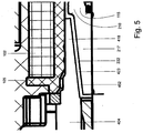
- the fourth embodiment according to Fig. 5 differs from the second embodiment according to Fig. 3 only by the differently shaped receiving portion, so that the same or structurally comparable parts as the embodiment according to Fig. 3 bear the same reference numerals.
- the in Fig. 5 Anchor 210 shown the same as the off Fig. 3
- the receiving part 418 is designed differently in that the inner peripheral surface 423 of the receiving portion 418 has a complementary to the cone shape of the insertion portion 217 cone shape, that is, is formed as an inner cone, which tapers in the conveying direction. This results in a de-energized coil 102, a secondary air gap 452 with almost constant thickness over the course of the insertion section 217, so that there is a favorable magnetic resistance by the low secondary air gap 452.
- the armature 210 Upon energization of the coil 102, the armature 210 is displaced, wherein the axial movement of the armature 210 increases the secondary air gap 452 in its thickness in proportion to the extent to which the armature 210 is displaced.
- the magnetic resistance changes over the stroke and accordingly influences the force with which the armature 210 is acted upon.
- the cone angle an exaggerated in the drawing, but noticeable axial component of the secondary air gap 452 defining parts is effective, the effect on the force is not greater than the radial component.
- Fig. 6 shows a further embodiment in which the configuration of the secondary air gap is again designed differently than in the preceding embodiments, wherein the same reference numerals as in the preceding embodiments show the same or structurally comparable parts.
- the armature 510 has an insertion section 517, which is rotationally symmetrical and whose limiting curve has a continuous, wave-like curved profile, with regions 517a of larger diameter and regions 517b of smaller diameter.
- the receiving section 518 of the second core part 504 is bounded by a rotationally symmetric envelope 523, which has regions of smaller inner diameter 523a and regions of larger inner diameter 523b. This results in a secondary air gap 552, which fluctuates over the course in its strength, wherein upon excitation of the coil 102 further changes in the strength of the secondary air gap 552 be induced, with the result of a corresponding influence on the magnetic resistance.
- curve courses 523, 517 are expediently complementary to one another, and expediently the maximum outer diameter of the insertion section 517 is smaller than the minimum inner diameter of the receiving section 518 so that the second core part 504 can be formed in one piece in particular and the armature 510 Direction of the first core part 103 can be used in the second core part 504.
- Figs. 7A to 7C 12 shows a schematic view of an electromagnetic pump 700 without representing a coil, other drive components, such as springs, or connection components to a pump space 707.
- an armature 710 is arranged, which armature 710 is axially displaceable in a conveying direction.
- the pump space 707 is limited by magnetic field guiding components 703, which for example correspond to the core parts 103, 104 and the coil carrier 105 shown in the first embodiment, but can also take other forms.
- a primary air gap is defined by a distance between the armature 710 and a conical counterpart 719.
- the armature 710 has a frustoconical contour tapering in the stroke direction in its front region 715 facing the counterpart 719.
- the conical counterpart 719 is formed on one of the magnetic field guiding components 703.
- the armature 710 in an end section facing away from the counterpart 719 and designated as an insertion section 717, has an annular outer projection 720 extending from a counter-cone 719 opposite end face of the armature 710 extends over about one sixth of the insertion portion 717 and projects radially to about a center of the secondary air gap.
- the components 703 include a receiving portion 718 in which the insertion portion 717 of the armature 710 is inserted.
- a radial inner projection 721 is arranged, which projects approximately to a center of the secondary air gap, so that the inner projection 721 and the outer projection 720 of the insertion 718 do not abut each other during a movement of the armature 710.
- Fig. 7A the outer projection 721 is arranged on a side of the inner projection 720 facing away from the pump space 707.
- a negative overlap there is no radial overlap of the outer surface of the outer projection and the inner surface of the inner projection, which is referred to herein as a negative overlap.
- the position shown of the armature 710 is a non-energized stroke position, wherein a coil, not shown, is not energized and the armature 710 is biased, for example by a spring in the stroke position shown. It is understood that a stop prevents the armature 710 against further biasing against a bias of the spring.
- Fig. 7B shows the armature 710 in a middle stroke position, wherein the inner surface of the inner projection 721 is disposed opposite to the outer surface of the outer projection 720.
- Fig. 7C shows the armature 710 in a deflected stroke position with the armature 710 fully extended out of the receiving portion 718, and with the front portion 715 of the armature 710 shown just before abutting against the counter-cone 719. Also in this position, there is a negative overlap between the inner projection 721 and the outer projection 720.
- the magnetic resistance of the entire assembly is higher than with positive coverage. Further, the magnetic resistance is further increased as the armature 710 moves out of the receiving portion 718.
- the behavior of the armature 710 is influenced to such an extent that when the armature 710 starts moving after the state in FIG Fig. 7A There is an approximately medium resistance, so that a pressure peak, which would result in a sudden energization of the coil in the pump chamber 707, is avoided. While the outer projection 720 on the inner projection 721 as in Fig. 7B moved past, the magnetic resistance decreases and the maximum force of the pump can be used for a delivery of a fluid. In the in Fig.
- Fig. 8 shows analogous to that in the Fig. 7A-C 1, a schematic view of another embodiment of an electromagnetic pump 800, without a coil, other drive components, such as springs, or connecting component to a pump chamber 807 represent.
- the same or comparable components have over the embodiments of Fig. 7 a reference number increased by 100, so that in the following a more detailed description of the position and nature of the components is dispensed with and only the differences are highlighted and described.
- the pump 800 of the embodiment according to Fig. 8 is constructed as the pump 700 of the embodiment according to Fig. 7 , wherein an insertion portion 817 of an armature 810 and a receiving portion 818, in which the armature 810 is inserted, from the insertion portion 717 and the Detect receiving section 818 of the seventh embodiment.
- the outer diameter of the insertion portion 817 and the inner diameter of the receiving portion 818 are approximately the same size, but a clearance is provided for sliding the armature 10 in the receiving portion 818.
- the insertion section 817 has, in a rear region facing away from a counter-cone 819, a groove 820a, an outer projection 820b being formed between an end face of the anchor 810 facing away from the counter-cone 819 and the groove 820a.
- the outer projection 820b has a same outer diameter as a remaining part of the insertion portion 817.
- the receiving portion 818 also has a groove 821a, wherein an outer projection 820b is formed between an end of the receiving portion 818 facing the counter-cone 819 and the groove 820a.
- the outer projection 820b has a same outer diameter as a remaining part 817a of the insertion section 817.
- FIG. 12 shows the armature 810 in a middle stroke position with the inner surface of the inner projection 821b facing the outer surface of the outer projection 820b.
- Fig. 9 shows an electromagnetic pump 900 designed as a metering pump, comprising a housing 901, an electromagnetic coil 902 arranged in the housing 901, a first ferromagnetic core part 903 and a second ferromagnetic core part 904.
- the electromagnetic coil 902 is wound on a coil support 905 and is wound in its Indoors of the first ferromagnetic core portion 903 and the second ferromagnetic core portion 904 each partially penetrated.
- the two ferromagnetic core parts 903, 904 are spaced from each other by a pumping space 907 defining a distance 906, wherein the first ferromagnetic core part 903 has a feed line 908 and the second ferromagnetic core part 904 has a discharge line 909 for a fluid to be conveyed.
- a pumping space 907 defining a distance 906
- the first ferromagnetic core part 903 has a feed line 908
- the second ferromagnetic core part 904 has a discharge line 909 for a fluid to be conveyed.
- a movable, ferromagnetic armature 910 Arranged in the pump chamber 907 is a movable, ferromagnetic armature 910, which armature 910 is biased in a conveying direction 912 of the electromagnetic pump 900 by a spring 911 arranged between the armature 910 and the first core part 903.
- the armature 910 has a substantially hollow cylindrical shape and is penetrated by a piston rod 913 in its entire longitudinal extension, wherein the piston rod 913 projects beyond the armature 110 with one end 913a in the conveying direction 912 and abuts against the drain line 909 and this with fully de-energized coil 902 closes.
- the armature 910 In its first region 915 facing the first core part 903, the armature 910 has a frustoconical contour which tapers in the stroke direction.
- the first core part 903 has a cone-shaped counterpart 919 facing the armature 910 and complementary to the front area 915 of the armature 910, wherein a region between the armature 910 and the conical armature counterpart 919 is referred to as a primary air gap.
- the front region 915 protrudes into the axial distance between both core parts 903, 904.
- the armature 910 extends with an end facing away from the first core part 903, formed as an insertion section 917 in a receiving portion 818 of the second core part 904, wherein the front portion 915 of the armature 910 does not protrude radially beyond an end face of the receiving portion 918 of the second core part 904 facing the first core part 903, whereby core parts 903, 904 with a smaller diameter can also be used.
- the front area 915 of the armature 910 it is also possible for the front area 915 of the armature 910 to protrude radially beyond the end face of the receiving portion 918 facing the first core part 903.
- An area between the insertion portion 917 of the armature 910 and the receiving portion 918 of the second core part 904 is referred to as a secondary air gap.
- the region between the front region 915 of the armature 910 and the counterpart 919 of the first core part 903 defines a primary air gap 951 whose axial extension is maximized in the case of a deenergized coil 902.
- the peripheral surface of the insertion portion 917 of the armature 910 and the receiving portion 918 of the second core portion 904 facing the longitudinal axis 953 of the spool 902 define a substantially radial, secondary air gap 952 in the region in which they oppose.
- the magnetic force between the armature 910 and the first core part 903 is greater than the magnetic force between the armature 910 and the second core part 904 due to the resulting magnetic field in a closing operation of the first air gap 951.
- a conical portion 960 of the insertion portion 917 of the armature 910 tapers against the longitudinally tapered frusto-conical contour of the front portion 915 of the armature 910, starting from an end face 961 of the insertion portion 917.
- a cylindrical region 962 of the insertion section 917 which extends up to an end wall 963 of the Insertion section 917 extends, in which the drain line 909 in a recess 964, which is greater than the end 913a of the piston rod 913, opens.
- a conical portion 970 of the insertion portion 917 of the armature 910 extends partially in radial overlap with the conical portion 960 of the insertion portion 917, partially outside the receiving portion 918, in FIG Fig. 9
- the conical portion 970 of the insertion portion 917 of the armature 910 passes completely out of radial overlap with the conical portion 960 of the insertion portion 917.
- the conical portion 970 of the insertion portion 917 closes in the direction of federation through a continuous cylindrical Region 971 of the armature 910, which is surrounded in the non-energized state partially radially from the conical portion 960 of the insertion section 917.
- a cylindrical section 972 adjoins the conical section 970 of the insertion section 917, which is adjoined in turn by the frustoconical contour of the front section 915 of the armature 910 which tapers in the stroke direction and which faces from an annular end face 973 of the first core section 903 Anchor 910 is limited.
- the conical section 970 constitutes slightly more than one sixth of the axial extent of the insertion section 917, which extends from a front side 974 of the armature 910 facing the drain line 909 to the cylindrical section 972, but without it.
- the conical section 960 constitutes slightly more than one sixth of the axial extent of the receiving section 916.
- the conical section 970 of the insertion section 917 which tapers counter to the stroke direction, is steeper than the frustoconically tapering contour of the front section 915 of the armature 910, since for approximately the same radial alignment the front section 915 has a longer axial distance Available.
- the cone angle of the conical sections 970 and 960 is approximately the same and differs by less than 8 °.
- the cone angle front portion 915 of armature 910 and counterpart 919 is approximately the same and differs by less than 8 °.
- a check valve 980 is arranged, which is biased by a spring 981 in the direction of the stroke of the armature 910 corresponding closing direction.
- a sleeve 982 is arranged, the bore 983 of the piston rod 913 is partially penetrated.
- a suction space 984 radially surrounded by the sleeve 982 between the valve member of the check valve 980 and the end face of the piston rod 913 facing the supply line 908 is connected to the pump space 907, for example via a bore containing a valve in the piston rod 913 which is not is shown further.
- the check valve 980 prevents the escape of the fluid, and this is pressed through the connection in the pump chamber 907. If the armature 910 displaced by the spring 911 back to its original position, created in the suction chamber 984, a negative pressure which lifts the valve member of the check valve 980 and allows a backflow of fluid, while the fluid upon return of the armature 910 from the pump chamber 907 in the Drain line 909 is pressed. It can be seen that the spring 911 is supported on an end face of the sleeve 982. It can also be seen that the bores in both core parts 903, 904 have a through bore which has in stages from outside to inside increasing diameter, so that a simple assembly by inserting components such as the sleeve 982 or the check valve 980 is possible.
- Fig. 9 shown and explained above features on the armature 910, in particular arrangement, length and angle of the conical portion 970 of the insertion portion 917, which also referred to as a secondary cone can be, and on the cone-shaped counterpart 919, in particular length, diameter and angle, there are additional degrees of freedom to optimize the force curve as a function of the stroke. In the present embodiment, this achieves, inter alia, a sufficient acceleration at the beginning of the stroke, a rising force with the stroke for overriding the bias of the spring 911 and a moderate and certainly not too large excess force at the end of the movement of the armature 910.
- the armature 910 securely holds the end of the stroke, but strikes the conical counterpart 919 with only a slight excess of force, even with variable supply voltage and changing coil temperature. As a result, unnecessary introduced into the Dosierpumoe 900 vibrations and temperature increases are avoided, which leads to an extension of the service life.
- the air gaps in the operation of the electromagnetic pump can not be filled with air, but with the medium to be pumped, pump oil or other medium, and in particular also the mutual leadership favoring sleeve, such as Teflon or the like may include.
- the invention has been described above with reference to an embodiment of the electromagnetic magnetic pump as an injection pump with dosing. It is understood that instead of a metering cylinder, an armature acting as a piston can be used, or that the pump can also be designed as a diaphragm pump, in which the fluid to be delivered remains outside the air gaps.
- the invention has been described above with reference to embodiments in which the insertion section and the receiving portion are formed as one-piece parts. It is understood that these parts can be composed of several parts in terms of manufacturing technology, for example, a base part with a cylindrical contour and a shrunk or pressed bushing part, which is at least partially ferromagnetic and accordingly has a specific ferromagnetic contour.
- a base part with a cylindrical contour and a shrunk or pressed bushing part which is at least partially ferromagnetic and accordingly has a specific ferromagnetic contour.
- it is possible to assemble a modular assortment by means of a corresponding socket in which the characteristic in the region of the secondary air gap is influenced by the type of the usual lining or bushing.
Landscapes
- Engineering & Computer Science (AREA)
- Mechanical Engineering (AREA)
- General Engineering & Computer Science (AREA)
- Physics & Mathematics (AREA)
- Fluid Mechanics (AREA)
- Reciprocating Pumps (AREA)
- Compressors, Vaccum Pumps And Other Relevant Systems (AREA)
- Electromagnetic Pumps, Or The Like (AREA)
Claims (15)
- Pompe électromagnétique comprenantexactement une bobine (102 ; 902), ladite une bobine (102 ; 902) possédant un axe longitudinal (153 ; 953),un premier élément de noyau ferromagnétique (103 ; 903) disposé au moins partiellement dans ladite une bobine (102 ; 902),un second élément de noyau ferromagnétique (104 ; 204 ; 404 ; 504 ; 904) disposé au moins partiellement dans ladite une bobine (102 ; 902), etun induit ferromagnétique (110 ; 210 ; 310 ; 510 ; 910), une discontinuité magnétique primaire (151 ; 951) étant ménagée entre l'induit (110 ; 210 ; 310 ; 510 ; 910) et le premier élément de noyau (103 ; 903), une discontinuité magnétique secondaire radiale (152 ; 252 ; 352 ; 453 ; 553 ; 953) étant ménagée entre une partie d'insertion (117 ; 217 ; 317 ; 517 ; 917) de l'induit (110 ; 210 ; 310 ; 510 ; 910) et une partie de réception (118 ; 218 ; 418 ; 518 ; 918) qui fait face à l'axe longitudinal (153 ; 953) du second élément de noyau (104 ; 204 ; 404 ; 504 ; 904),l'induit ferromagnétique (110 ; 210 ; 310 ; 510 ; 910) présentant un contour tronconique, effilé dans le sens de la course, dans la zone avant (115 ; 915) qui fait face au premier élément de noyau (103 ; 903),
lors d'un processus de fermeture de la discontinuité magnétique primaire (151 ; 951), la force magnétique entre l'induit (110 ; 210 ; 310 ; 510 ; 910) et le premier élément de noyau (103 ; 903) étant supérieure à une force magnétique entre l'induit (110 ; 210 ; 310 ; 510 ; 910) et le second élément de noyau (104 ; 204 ; 404 ; 504 ; 904),
caractérisée en ce
que la partie d'insertion (117 ; 217 ; 517 ; 917) de l'induit (110 ; 210 ; 510 ; 910) possède au moins une partie conique qui forme un angle d'ouverture qui s'écarte du contour tronconique de la zone avant (115 ; 915) de l'induit ferromagnétique (110 ; 210 ; 310 ; 510 ; 910). - Pompe électromagnétique selon la revendication 1, caractérisée en ce que l'une au moins entre la partie d'insertion (117 ; 217 ; 317 ; 517 ; 917) de l'induit (110 ; 210 ; 310 ; 510) et la partie de réception (118; 218 ; 418 ; 518 ; 918) du second élément de noyau (104 ; 204 ; 404 ; 504 ; 904) présente un contour qui s'écarte du contour cylindrique sur une zone d'au moins un sixième de l'extension axiale maximale de la discontinuité magnétique secondaire (152 ; 252 ; 352 ; 453 ; 553 ; 953).
- Pompe électromagnétique selon la revendication 1 ou 2, caractérisée en ce que l'une au moins des partie d'insertion (217 ; 917) de l'induit (210 ; 910) et partie de réception (418 ; 918) du second élément de noyau (404 ; 904) a une forme conique sur une zone d'au moins un sixième de l'extension axiale maximale de la discontinuité magnétique secondaire (252 ; 453 ; 952).
- Pompe électromagnétique selon l'une des revendications 1 à 3, caractérisée en ce que la partie d'insertion (317) de l'induit (310) comprend un étagement (330) qui présente une discontinuité magnétique secondaire élargie.
- Pompe électromagnétique selon l'une des revendications 1 à 4, caractérisée en ce que la partie de réception (118) du second élément de noyau (104) comporte une saillie intérieure (121) qui est orientée vers l'axe longitudinal (153).
- Pompe électromagnétique selon l'une des revendications 1 à 5, caractérisée en ce que, dans la zone de la discontinuité magnétique secondaire (152 ; 252 ; 352 ; 453 ; 553 ; 952), le diamètre extérieur maximal de la partie d'insertion (117 ; 217 ; 317 ; 517 ; 917) de l'induit (110 ; 210 ; 310 ; 510 ; 910) est inférieur au diamètre intérieur minimal de la partie de réception (118 ; 218 ; 418 ; 518 ; 918) du second élément de noyau (104 ; 204 ; 404 ; 504 ; 904).
- Pompe électromagnétique selon l'une des revendications précédentes, caractérisée en ce que la zone avant (115) de l'induit (110 ; 210 ; 310 ; 510) fait saillie radialement d'un côté frontal, qui fait face au premier élément de noyau (103), de la partie de réception (118 ; 218 ; 418 ; 518) du second élément de noyau (104 ; 204 ; 404 ; 504).
- Pompe électromagnétique selon l'une des revendications précédentes, caractérisée en ce que la partie conique (970) de la partie d'insertion (117 ; 217 ; 517 ; 917) de l'induit (110 ; 210 ; 510 ; 910) est effilée dans le sens opposé au contour tronconique, effilée dans le sens de la course, de la zone avant (115 ; 915) de l'induit (110 ; 210 ; 310 ; 510 ; 910).
- Pompe électromagnétique selon la revendication 8, caractérisée en ce que la partie conique (970) de la partie d'insertion (117 ; 217 ; 517 ; 917) de l'induit (110 ; 210 ; 510 ; 910) s'étend partiellement à l'extérieur de la partie de réception (118 ; 218 ; 418 ; 518 ; 918).
- Pompe électromagnétique selon l'une des revendications précédentes, caractérisée en ce que la partie conique (960), effilée dans le sens opposé au sens de la course, de la partie de réception (118 ; 218 ; 418 ; 518 ; 918) est adjacente à un côté avant (961), tourné vers le premier élément de noyau (103 ; 903), du second élément de noyau (104 ; 204 ; 404 ; 504 ; 904).
- Pompe électromagnétique selon l'une des revendications précédentes, caractérisée en ce que la partie conique (970), effilée dans le sens opposé au sens de la course, de la partie d'insertion (917) forme un angle plus obtus que le contour tronconique, effilée dans le sens de la course, de la zone avant (915) de l'induit (910).
- Pompe électromagnétique selon l'une des revendications précédentes, caractérisée en ce que la zone (962) de la partie de réception (918), qui est orientée dans le sens de pompage (914) et qui est située à l'extérieur de la partie conique (960), effilée dans le sens opposé au sens de la course, de la partie de réception (918) a une forme cylindrique et en ce que la zone (971) de la partie d'insertion (917), qui pénètre dans la zone cylindrique de la partie de réception (918), a une forme cylindrique.
- Pompe électromagnétique selon l'une des revendications précédentes, caractérisée en ce que l'induit (110 ; 210 ; 310 ; 510 ; 910) a son diamètre maximum (972) dans un espace, entouré par la bobine (902), à l'extérieur de la partie de réception (118 ; 218 ; 418 ; 518 ; 918) du second élément de noyau (104 ; 204 ; 404 ; 504 ; 904) et à l'extérieur du premier élément de noyau (103 ; 903).
- Pompe électromagnétique selon l'une des revendications précédentes, caractérisée en ce que la surface de piston efficace, orientée dans le sens de pompage, de l'induit (110 ; 210 ; 310 ; 510 ; 910) est supérieure à la surface de piston efficace, orientée dans le sens de la course, de l'induit (110 ; 210 ; 310 ; 510 ; 910).
- Pompe électromagnétique selon l'une des revendications précédentes, caractérisée en ce que la pompe est choisie dans le groupe comprenant une pompe à piston alternatif, une pompe à diaphragme, une pompe de régulation de pression et une pompe doseuse.
Applications Claiming Priority (2)
| Application Number | Priority Date | Filing Date | Title |
|---|---|---|---|
| DE201210012779 DE102012012779A1 (de) | 2012-06-25 | 2012-06-25 | Elektromagnetische Pumpe |
| PCT/EP2013/001850 WO2014000878A1 (fr) | 2012-06-25 | 2013-06-24 | Pompe électromagnétique |
Publications (2)
| Publication Number | Publication Date |
|---|---|
| EP2880312A1 EP2880312A1 (fr) | 2015-06-10 |
| EP2880312B1 true EP2880312B1 (fr) | 2016-04-13 |
Family
ID=48747505
Family Applications (1)
| Application Number | Title | Priority Date | Filing Date |
|---|---|---|---|
| EP13734331.5A Not-in-force EP2880312B1 (fr) | 2012-06-25 | 2013-06-24 | Pompe électromagnétique |
Country Status (5)
| Country | Link |
|---|---|
| US (1) | US20150104338A1 (fr) |
| EP (1) | EP2880312B1 (fr) |
| CN (1) | CN104411971B (fr) |
| DE (1) | DE102012012779A1 (fr) |
| WO (1) | WO2014000878A1 (fr) |
Families Citing this family (3)
| Publication number | Priority date | Publication date | Assignee | Title |
|---|---|---|---|---|
| JP2018519449A (ja) * | 2015-04-13 | 2018-07-19 | イートン コーポレーションEaton Corporation | サドル燃料タンクの電子ベンティング |
| RU2660744C1 (ru) * | 2016-07-08 | 2018-07-09 | Федеральное государственное бюджетное образовательное учреждение высшего образования "Казанский государственный аграрный университет" (ФГБОУ ВО Казанский ГАУ) | Поршневой насос |
| CN115863047B (zh) * | 2022-11-17 | 2024-06-28 | 广州骏发电气设备有限公司 | 一种变压器低压线圈自动整形装置及其使用方法 |
Family Cites Families (17)
| Publication number | Priority date | Publication date | Assignee | Title |
|---|---|---|---|---|
| US2006592A (en) * | 1934-11-10 | 1935-07-02 | Freeman Earle | Well pumping apparatus |
| US2222823A (en) * | 1938-03-10 | 1940-11-26 | Fluidpoise Mfg Company Inc | Pumping apparatus |
| DE1101960B (de) * | 1960-01-26 | 1961-03-09 | Otto Muehlschlegel Dipl Ing | Elektromagnetisch angetriebene Freischwingerpumpe |
| US3883839A (en) * | 1973-10-29 | 1975-05-13 | Barber Colman Co | Positioning device |
| DD128346A1 (de) * | 1976-11-18 | 1977-11-16 | Eberhard Kallenbach | Schnellwirkender elektromagnet mit magneto-mechanischer abbremsung |
| FR2428343A1 (fr) * | 1978-06-05 | 1980-01-04 | Peugeot Aciers Et Outillage | Dispositif electromoteur pour engendrer des mouvements notamment lineaires |
| US4308475A (en) * | 1978-07-18 | 1981-12-29 | Sundstrand Corporation | Solenoid pump adapted for noiseless operation |
| DE3504789A1 (de) * | 1985-02-13 | 1986-08-14 | Webasto-Werk W. Baier GmbH & Co, 8035 Gauting | Elektromagnetisch betaetigte kolbenpumpe |
| US5562428A (en) * | 1995-04-07 | 1996-10-08 | Outboard Marine Corporation | Fuel injection pump having an adjustable inlet poppet valve |
| CZ292533B6 (cs) * | 1999-11-18 | 2003-10-15 | Brano-Ateso A.S., Člen Brano Group | Elektromagnetické pístové čerpadlo |
| US7078833B2 (en) * | 2002-05-31 | 2006-07-18 | Minebea Co., Ltd. | Force motor with increased proportional stroke |
| KR100725691B1 (ko) * | 2004-11-30 | 2007-06-07 | 니혼 덴산 산쿄 가부시키가이샤 | 리니어 액추에이터를 사용한 펌프 장치 |
| DE102005015117B4 (de) * | 2005-04-01 | 2007-04-26 | Webasto Ag | Hubkolbenbrennstoffpumpe und Verfahren zum Starten und Betreiben einer Kraftfahrzeugheizung |
| NZ541408A (en) * | 2005-07-21 | 2007-02-23 | Fisher & Paykel Appliances Ltd | Taper fit mounting of stator in free piston compressor motor |
| ATE512300T1 (de) * | 2006-07-12 | 2011-06-15 | Delphi Tech Holding Sarl | Dosierpumpe für eines reduktionsmittels |
| DE102008058046A1 (de) * | 2008-11-18 | 2010-05-20 | Thomas Magnete Gmbh | Hubkolbenpumpe |
| DE102010013106A1 (de) * | 2010-03-26 | 2011-09-29 | Thomas Magnete Gmbh | Pumpe |
-
2012
- 2012-06-25 DE DE201210012779 patent/DE102012012779A1/de not_active Withdrawn
-
2013
- 2013-06-24 CN CN201380033898.6A patent/CN104411971B/zh not_active Expired - Fee Related
- 2013-06-24 EP EP13734331.5A patent/EP2880312B1/fr not_active Not-in-force
- 2013-06-24 WO PCT/EP2013/001850 patent/WO2014000878A1/fr not_active Ceased
-
2014
- 2014-12-19 US US14/576,336 patent/US20150104338A1/en not_active Abandoned
Also Published As
| Publication number | Publication date |
|---|---|
| US20150104338A1 (en) | 2015-04-16 |
| EP2880312A1 (fr) | 2015-06-10 |
| CN104411971A (zh) | 2015-03-11 |
| WO2014000878A1 (fr) | 2014-01-03 |
| DE102012012779A1 (de) | 2014-03-27 |
| CN104411971B (zh) | 2016-12-07 |
Similar Documents
| Publication | Publication Date | Title |
|---|---|---|
| EP2308064B1 (fr) | Système d électroaimant de levage et système de soupape | |
| DE3541938C2 (de) | Magnet-Überströmventil | |
| EP1818951B1 (fr) | Electroaimant de levage | |
| DE102016119214A1 (de) | Solenoidventil | |
| EP2475887A1 (fr) | Pompe à armature oscillante | |
| DE19522187C2 (de) | Fluidsteuerventil | |
| WO2014000878A1 (fr) | Pompe électromagnétique | |
| DE102011105586B4 (de) | Ventil | |
| DE2657197C2 (fr) | ||
| EP0651858B1 (fr) | Pompe a entrainement electromagnetique | |
| EP0708243B1 (fr) | Pompe pour délivrer des liquides | |
| DE112005002789T5 (de) | Stellantrieb | |
| WO2019025063A1 (fr) | Soupape à actionnement électromagnétique et pompe à carburant haute pression | |
| DE102008064409A1 (de) | Vorgesteuertes Ventil und ventilgesteuerte Hydromaschine | |
| EP3586696B1 (fr) | Pompe à boisson | |
| DE2410768C3 (de) | Elektromagnetische Pumpe | |
| DE102014220670A1 (de) | Elektromagnetisch betätigbares Proportionalventil sowie Kraftstoffhochdruckpumpe mit einem solchen Proportionalventil | |
| DE102008034609B4 (de) | Elektromagnet | |
| DE2206882A1 (de) | Elektromagnetisch betätigte Kolben pumpe fur Flüssigkeiten | |
| EP3078854B1 (fr) | Pompe vibrante | |
| DE102008047364B4 (de) | Hubmagnet mit Lagerung des Hubankerkolbens im Magnetgehäuse | |
| WO2018019483A1 (fr) | Circuit magnétique, soupape d'aspiration à actionnement magnétique et pompe à carburant haute pression | |
| DE202016001785U1 (de) | Ventil | |
| DE102016003367A1 (de) | Ventil | |
| EP2405168B1 (fr) | Corps de soupape et soupape électromagnétique correspondante |
Legal Events
| Date | Code | Title | Description |
|---|---|---|---|
| PUAI | Public reference made under article 153(3) epc to a published international application that has entered the european phase |
Free format text: ORIGINAL CODE: 0009012 |
|
| 17P | Request for examination filed |
Effective date: 20141212 |
|
| AK | Designated contracting states |
Kind code of ref document: A1 Designated state(s): AL AT BE BG CH CY CZ DE DK EE ES FI FR GB GR HR HU IE IS IT LI LT LU LV MC MK MT NL NO PL PT RO RS SE SI SK SM TR |
|
| AX | Request for extension of the european patent |
Extension state: BA ME |
|
| DAX | Request for extension of the european patent (deleted) | ||
| GRAP | Despatch of communication of intention to grant a patent |
Free format text: ORIGINAL CODE: EPIDOSNIGR1 |
|
| INTG | Intention to grant announced |
Effective date: 20151019 |
|
| GRAS | Grant fee paid |
Free format text: ORIGINAL CODE: EPIDOSNIGR3 |
|
| GRAA | (expected) grant |
Free format text: ORIGINAL CODE: 0009210 |
|
| AK | Designated contracting states |
Kind code of ref document: B1 Designated state(s): AL AT BE BG CH CY CZ DE DK EE ES FI FR GB GR HR HU IE IS IT LI LT LU LV MC MK MT NL NO PL PT RO RS SE SI SK SM TR |
|
| REG | Reference to a national code |
Ref country code: GB Ref legal event code: FG4D Free format text: NOT ENGLISH |
|
| REG | Reference to a national code |
Ref country code: AT Ref legal event code: REF Ref document number: 790462 Country of ref document: AT Kind code of ref document: T Effective date: 20160415 Ref country code: CH Ref legal event code: EP |
|
| REG | Reference to a national code |
Ref country code: IE Ref legal event code: FG4D Free format text: LANGUAGE OF EP DOCUMENT: GERMAN |
|
| REG | Reference to a national code |
Ref country code: DE Ref legal event code: R096 Ref document number: 502013002602 Country of ref document: DE |
|
| REG | Reference to a national code |
Ref country code: FR Ref legal event code: PLFP Year of fee payment: 4 |
|
| REG | Reference to a national code |
Ref country code: LT Ref legal event code: MG4D |
|
| REG | Reference to a national code |
Ref country code: NL Ref legal event code: MP Effective date: 20160413 |
|
| PG25 | Lapsed in a contracting state [announced via postgrant information from national office to epo] |
Ref country code: PL Free format text: LAPSE BECAUSE OF FAILURE TO SUBMIT A TRANSLATION OF THE DESCRIPTION OR TO PAY THE FEE WITHIN THE PRESCRIBED TIME-LIMIT Effective date: 20160413 Ref country code: NL Free format text: LAPSE BECAUSE OF FAILURE TO SUBMIT A TRANSLATION OF THE DESCRIPTION OR TO PAY THE FEE WITHIN THE PRESCRIBED TIME-LIMIT Effective date: 20160413 Ref country code: FI Free format text: LAPSE BECAUSE OF FAILURE TO SUBMIT A TRANSLATION OF THE DESCRIPTION OR TO PAY THE FEE WITHIN THE PRESCRIBED TIME-LIMIT Effective date: 20160413 Ref country code: LT Free format text: LAPSE BECAUSE OF FAILURE TO SUBMIT A TRANSLATION OF THE DESCRIPTION OR TO PAY THE FEE WITHIN THE PRESCRIBED TIME-LIMIT Effective date: 20160413 Ref country code: NO Free format text: LAPSE BECAUSE OF FAILURE TO SUBMIT A TRANSLATION OF THE DESCRIPTION OR TO PAY THE FEE WITHIN THE PRESCRIBED TIME-LIMIT Effective date: 20160713 |
|
| PG25 | Lapsed in a contracting state [announced via postgrant information from national office to epo] |
Ref country code: SE Free format text: LAPSE BECAUSE OF FAILURE TO SUBMIT A TRANSLATION OF THE DESCRIPTION OR TO PAY THE FEE WITHIN THE PRESCRIBED TIME-LIMIT Effective date: 20160413 Ref country code: ES Free format text: LAPSE BECAUSE OF FAILURE TO SUBMIT A TRANSLATION OF THE DESCRIPTION OR TO PAY THE FEE WITHIN THE PRESCRIBED TIME-LIMIT Effective date: 20160413 Ref country code: PT Free format text: LAPSE BECAUSE OF FAILURE TO SUBMIT A TRANSLATION OF THE DESCRIPTION OR TO PAY THE FEE WITHIN THE PRESCRIBED TIME-LIMIT Effective date: 20160816 Ref country code: GR Free format text: LAPSE BECAUSE OF FAILURE TO SUBMIT A TRANSLATION OF THE DESCRIPTION OR TO PAY THE FEE WITHIN THE PRESCRIBED TIME-LIMIT Effective date: 20160714 Ref country code: LV Free format text: LAPSE BECAUSE OF FAILURE TO SUBMIT A TRANSLATION OF THE DESCRIPTION OR TO PAY THE FEE WITHIN THE PRESCRIBED TIME-LIMIT Effective date: 20160413 Ref country code: HR Free format text: LAPSE BECAUSE OF FAILURE TO SUBMIT A TRANSLATION OF THE DESCRIPTION OR TO PAY THE FEE WITHIN THE PRESCRIBED TIME-LIMIT Effective date: 20160413 Ref country code: RS Free format text: LAPSE BECAUSE OF FAILURE TO SUBMIT A TRANSLATION OF THE DESCRIPTION OR TO PAY THE FEE WITHIN THE PRESCRIBED TIME-LIMIT Effective date: 20160413 |
|
| PG25 | Lapsed in a contracting state [announced via postgrant information from national office to epo] |
Ref country code: BE Free format text: LAPSE BECAUSE OF NON-PAYMENT OF DUE FEES Effective date: 20160630 |
|
| REG | Reference to a national code |
Ref country code: DE Ref legal event code: R097 Ref document number: 502013002602 Country of ref document: DE |
|
| PG25 | Lapsed in a contracting state [announced via postgrant information from national office to epo] |
Ref country code: DK Free format text: LAPSE BECAUSE OF FAILURE TO SUBMIT A TRANSLATION OF THE DESCRIPTION OR TO PAY THE FEE WITHIN THE PRESCRIBED TIME-LIMIT Effective date: 20160413 Ref country code: EE Free format text: LAPSE BECAUSE OF FAILURE TO SUBMIT A TRANSLATION OF THE DESCRIPTION OR TO PAY THE FEE WITHIN THE PRESCRIBED TIME-LIMIT Effective date: 20160413 Ref country code: SK Free format text: LAPSE BECAUSE OF FAILURE TO SUBMIT A TRANSLATION OF THE DESCRIPTION OR TO PAY THE FEE WITHIN THE PRESCRIBED TIME-LIMIT Effective date: 20160413 Ref country code: MC Free format text: LAPSE BECAUSE OF FAILURE TO SUBMIT A TRANSLATION OF THE DESCRIPTION OR TO PAY THE FEE WITHIN THE PRESCRIBED TIME-LIMIT Effective date: 20160413 Ref country code: CZ Free format text: LAPSE BECAUSE OF FAILURE TO SUBMIT A TRANSLATION OF THE DESCRIPTION OR TO PAY THE FEE WITHIN THE PRESCRIBED TIME-LIMIT Effective date: 20160413 Ref country code: RO Free format text: LAPSE BECAUSE OF FAILURE TO SUBMIT A TRANSLATION OF THE DESCRIPTION OR TO PAY THE FEE WITHIN THE PRESCRIBED TIME-LIMIT Effective date: 20160413 |
|
| REG | Reference to a national code |
Ref country code: CH Ref legal event code: PL |
|
| PLBE | No opposition filed within time limit |
Free format text: ORIGINAL CODE: 0009261 |
|
| STAA | Information on the status of an ep patent application or granted ep patent |
Free format text: STATUS: NO OPPOSITION FILED WITHIN TIME LIMIT |
|
| PG25 | Lapsed in a contracting state [announced via postgrant information from national office to epo] |
Ref country code: SM Free format text: LAPSE BECAUSE OF FAILURE TO SUBMIT A TRANSLATION OF THE DESCRIPTION OR TO PAY THE FEE WITHIN THE PRESCRIBED TIME-LIMIT Effective date: 20160413 |
|
| 26N | No opposition filed |
Effective date: 20170116 |
|
| REG | Reference to a national code |
Ref country code: IE Ref legal event code: MM4A |
|
| PG25 | Lapsed in a contracting state [announced via postgrant information from national office to epo] |
Ref country code: LI Free format text: LAPSE BECAUSE OF NON-PAYMENT OF DUE FEES Effective date: 20160630 Ref country code: CH Free format text: LAPSE BECAUSE OF NON-PAYMENT OF DUE FEES Effective date: 20160630 |
|
| PG25 | Lapsed in a contracting state [announced via postgrant information from national office to epo] |
Ref country code: IE Free format text: LAPSE BECAUSE OF NON-PAYMENT OF DUE FEES Effective date: 20160624 Ref country code: SI Free format text: LAPSE BECAUSE OF FAILURE TO SUBMIT A TRANSLATION OF THE DESCRIPTION OR TO PAY THE FEE WITHIN THE PRESCRIBED TIME-LIMIT Effective date: 20160413 |
|
| REG | Reference to a national code |
Ref country code: FR Ref legal event code: PLFP Year of fee payment: 5 |
|
| GBPC | Gb: european patent ceased through non-payment of renewal fee |
Effective date: 20170624 |
|
| PG25 | Lapsed in a contracting state [announced via postgrant information from national office to epo] |
Ref country code: GB Free format text: LAPSE BECAUSE OF NON-PAYMENT OF DUE FEES Effective date: 20170624 |
|
| PG25 | Lapsed in a contracting state [announced via postgrant information from national office to epo] |
Ref country code: HU Free format text: LAPSE BECAUSE OF FAILURE TO SUBMIT A TRANSLATION OF THE DESCRIPTION OR TO PAY THE FEE WITHIN THE PRESCRIBED TIME-LIMIT; INVALID AB INITIO Effective date: 20130624 |
|
| REG | Reference to a national code |
Ref country code: FR Ref legal event code: PLFP Year of fee payment: 6 |
|
| PG25 | Lapsed in a contracting state [announced via postgrant information from national office to epo] |
Ref country code: CY Free format text: LAPSE BECAUSE OF FAILURE TO SUBMIT A TRANSLATION OF THE DESCRIPTION OR TO PAY THE FEE WITHIN THE PRESCRIBED TIME-LIMIT Effective date: 20160413 Ref country code: LU Free format text: LAPSE BECAUSE OF NON-PAYMENT OF DUE FEES Effective date: 20160624 Ref country code: IS Free format text: LAPSE BECAUSE OF FAILURE TO SUBMIT A TRANSLATION OF THE DESCRIPTION OR TO PAY THE FEE WITHIN THE PRESCRIBED TIME-LIMIT Effective date: 20160413 Ref country code: MK Free format text: LAPSE BECAUSE OF FAILURE TO SUBMIT A TRANSLATION OF THE DESCRIPTION OR TO PAY THE FEE WITHIN THE PRESCRIBED TIME-LIMIT Effective date: 20160413 Ref country code: MT Free format text: LAPSE BECAUSE OF FAILURE TO SUBMIT A TRANSLATION OF THE DESCRIPTION OR TO PAY THE FEE WITHIN THE PRESCRIBED TIME-LIMIT Effective date: 20160413 |
|
| PG25 | Lapsed in a contracting state [announced via postgrant information from national office to epo] |
Ref country code: BG Free format text: LAPSE BECAUSE OF FAILURE TO SUBMIT A TRANSLATION OF THE DESCRIPTION OR TO PAY THE FEE WITHIN THE PRESCRIBED TIME-LIMIT Effective date: 20160413 |
|
| PG25 | Lapsed in a contracting state [announced via postgrant information from national office to epo] |
Ref country code: TR Free format text: LAPSE BECAUSE OF FAILURE TO SUBMIT A TRANSLATION OF THE DESCRIPTION OR TO PAY THE FEE WITHIN THE PRESCRIBED TIME-LIMIT Effective date: 20160413 Ref country code: AL Free format text: LAPSE BECAUSE OF FAILURE TO SUBMIT A TRANSLATION OF THE DESCRIPTION OR TO PAY THE FEE WITHIN THE PRESCRIBED TIME-LIMIT Effective date: 20160413 |
|
| REG | Reference to a national code |
Ref country code: AT Ref legal event code: MM01 Ref document number: 790462 Country of ref document: AT Kind code of ref document: T Effective date: 20180624 |
|
| PG25 | Lapsed in a contracting state [announced via postgrant information from national office to epo] |
Ref country code: AT Free format text: LAPSE BECAUSE OF NON-PAYMENT OF DUE FEES Effective date: 20180624 |
|
| PGFP | Annual fee paid to national office [announced via postgrant information from national office to epo] |
Ref country code: FR Payment date: 20200619 Year of fee payment: 8 |
|
| PGFP | Annual fee paid to national office [announced via postgrant information from national office to epo] |
Ref country code: DE Payment date: 20200630 Year of fee payment: 8 |
|
| PGFP | Annual fee paid to national office [announced via postgrant information from national office to epo] |
Ref country code: IT Payment date: 20200625 Year of fee payment: 8 |
|
| REG | Reference to a national code |
Ref country code: DE Ref legal event code: R119 Ref document number: 502013002602 Country of ref document: DE |
|
| PG25 | Lapsed in a contracting state [announced via postgrant information from national office to epo] |
Ref country code: DE Free format text: LAPSE BECAUSE OF NON-PAYMENT OF DUE FEES Effective date: 20220101 |
|
| PG25 | Lapsed in a contracting state [announced via postgrant information from national office to epo] |
Ref country code: FR Free format text: LAPSE BECAUSE OF NON-PAYMENT OF DUE FEES Effective date: 20210630 |
|
| PG25 | Lapsed in a contracting state [announced via postgrant information from national office to epo] |
Ref country code: IT Free format text: LAPSE BECAUSE OF NON-PAYMENT OF DUE FEES Effective date: 20210624 |