EP2880329B1 - Nehmerzylinder für eine hydraulische ausrückanordnung zur betätigung einer kupplung - Google Patents
Nehmerzylinder für eine hydraulische ausrückanordnung zur betätigung einer kupplung Download PDFInfo
- Publication number
- EP2880329B1 EP2880329B1 EP13753556.3A EP13753556A EP2880329B1 EP 2880329 B1 EP2880329 B1 EP 2880329B1 EP 13753556 A EP13753556 A EP 13753556A EP 2880329 B1 EP2880329 B1 EP 2880329B1
- Authority
- EP
- European Patent Office
- Prior art keywords
- sealing
- annular
- slave cylinder
- annular part
- annular piston
- Prior art date
- Legal status (The legal status is an assumption and is not a legal conclusion. Google has not performed a legal analysis and makes no representation as to the accuracy of the status listed.)
- Active
Links
Images
Classifications
-
- F—MECHANICAL ENGINEERING; LIGHTING; HEATING; WEAPONS; BLASTING
- F16—ENGINEERING ELEMENTS AND UNITS; GENERAL MEASURES FOR PRODUCING AND MAINTAINING EFFECTIVE FUNCTIONING OF MACHINES OR INSTALLATIONS; THERMAL INSULATION IN GENERAL
- F16D—COUPLINGS FOR TRANSMITTING ROTATION; CLUTCHES; BRAKES
- F16D25/00—Fluid-actuated clutches
- F16D25/08—Fluid-actuated clutches with fluid-actuated member not rotating with a clutching member
- F16D25/082—Fluid-actuated clutches with fluid-actuated member not rotating with a clutching member the line of action of the fluid-actuated members co-inciding with the axis of rotation
- F16D25/083—Actuators therefor
-
- F—MECHANICAL ENGINEERING; LIGHTING; HEATING; WEAPONS; BLASTING
- F16—ENGINEERING ELEMENTS AND UNITS; GENERAL MEASURES FOR PRODUCING AND MAINTAINING EFFECTIVE FUNCTIONING OF MACHINES OR INSTALLATIONS; THERMAL INSULATION IN GENERAL
- F16J—PISTONS; CYLINDERS; SEALINGS
- F16J15/00—Sealings
- F16J15/16—Sealings between relatively-moving surfaces
- F16J15/32—Sealings between relatively-moving surfaces with elastic sealings, e.g. O-rings
- F16J15/3204—Sealings between relatively-moving surfaces with elastic sealings, e.g. O-rings with at least one lip
- F16J15/322—Sealings between relatively-moving surfaces with elastic sealings, e.g. O-rings with at least one lip supported in a direction perpendicular to the surfaces
-
- F—MECHANICAL ENGINEERING; LIGHTING; HEATING; WEAPONS; BLASTING
- F16—ENGINEERING ELEMENTS AND UNITS; GENERAL MEASURES FOR PRODUCING AND MAINTAINING EFFECTIVE FUNCTIONING OF MACHINES OR INSTALLATIONS; THERMAL INSULATION IN GENERAL
- F16J—PISTONS; CYLINDERS; SEALINGS
- F16J15/00—Sealings
- F16J15/16—Sealings between relatively-moving surfaces
- F16J15/32—Sealings between relatively-moving surfaces with elastic sealings, e.g. O-rings
- F16J15/3204—Sealings between relatively-moving surfaces with elastic sealings, e.g. O-rings with at least one lip
- F16J15/3232—Sealings between relatively-moving surfaces with elastic sealings, e.g. O-rings with at least one lip having two or more lips
- F16J15/3236—Sealings between relatively-moving surfaces with elastic sealings, e.g. O-rings with at least one lip having two or more lips with at least one lip for each surface, e.g. U-cup packings
-
- F—MECHANICAL ENGINEERING; LIGHTING; HEATING; WEAPONS; BLASTING
- F16—ENGINEERING ELEMENTS AND UNITS; GENERAL MEASURES FOR PRODUCING AND MAINTAINING EFFECTIVE FUNCTIONING OF MACHINES OR INSTALLATIONS; THERMAL INSULATION IN GENERAL
- F16D—COUPLINGS FOR TRANSMITTING ROTATION; CLUTCHES; BRAKES
- F16D2300/00—Special features for couplings or clutches
- F16D2300/08—Details or arrangements of sealings not provided for in group F16D3/84
Definitions
- the present invention relates to a slave cylinder for a hydraulic disengagement assembly for actuating a clutch.
- the hydraulic release system of the clutch which is in particular a double clutch, cover fixed and arranged concentrically.
- a slave cylinder for a hydraulic release system of a friction clutch of motor vehicles, wherein the slave cylinder has a concentrically arranged to a transmission input shaft housing.
- a guide sleeve is radially spaced from the cylindrical inner surface of the housing.
- annular pressure chamber Between the said inner surface and the cylindrical outer surface of the guide sleeve there is an annular pressure chamber in which an annular piston is arranged axially displaceable.
- the annular piston is provided with a ring seal, the sealing lips are arranged radially spread.
- the ring piston has at least one additional seal carrier for receiving the annular seal, which reduces an annular gap between the annular piston and the inner surface of the housing and / or an annular gap between the annular piston and the outer surface of the guide sleeve upon pressurization of the pressure chamber.
- WO 00/06921 shows a hydraulically actuated release system for a friction clutch of a motor vehicle, which has a piston-cylinder unit comprising an annular, cylindrical housing and an inner guide tube with an annular annular pressure chamber therebetween.
- a piston-cylinder unit comprising an annular, cylindrical housing and an inner guide tube with an annular annular pressure chamber therebetween.
- an axially displaceable annular piston is arranged in the pressure chamber, which has at the front end a ring seal with applied to the inside of the housing and on the outside of the guide tube sealing lips.
- the seal is positively connected to lock on the annular piston with a ring piston attached to the retaining ring and an end portion of the piston.
- slave cylinders for hydraulic release systems are from the DE 19949205 A1 and the FR 2772443 A1 known.
- the object of the present invention is to provide a slave cylinder for a hydraulic disengagement assembly for actuating a clutch in such a way that the volume absorption and the hysteresis of the sealing ring provided on the annular piston are as small as possible.
- the present invention relates to a slave cylinder for a disengagement assembly for actuating a clutch having a cylindrical housing and a concentrically arranged and radially spaced, cylindrical guide tube, between them form an annular pressure chamber in which an annular piston is arranged axially displaceable.
- the annular piston has a sealing ring on its side facing the pressure chamber.
- the sealing ring comprises an axially extending sealing neck or sealing area.
- An outer ring member is disposed between the outside of the sealing portion and the cylindrical inner surface of the housing. Further, an inner ring member is provided between the inside of the sealing portion and the cylindrical outer surface of the guide tube.
- the sealing ring has a Y-shaped profile which comprises a sealing foot, the sealing area axially adjoining thereto and then an outer sealing lip and an inner sealing lip.
- the sealing lips run apart in a V-shape.
- the outer sealing lip is located on the cylindrical inner surface of the housing and the inner sealing lip abuts against the cylindrical outer surface of the guide tube.
- the sealing foot of the sealing ring is positively and tightly held in a complementary to him formed recess of the annular piston, wherein the recess has expediently undercuts.
- a particularly good seal is achieved under a load, if said sealing region, starting from the sealing foot of the sealing ring in each case arcuately outwardly to the outer sealing lip or inwardly to the inner sealing lip preferably expands and, accordingly, preferably also the outer ring member on the inside , starting from the side of the annular piston in the sealing region of the sealing ring extends arcuately outwards and the inner ring part on the outside, extends arcuately inward starting from the side of the annular piston in the sealing region of the sealing ring.
- the sealing ring is held in the sealing area form-fitting between the outer ring member and the inner ring member.
- annular piston facing surface of the outer ring member are radially outside the recess on the annular piston and the annular piston facing surface of the inner ring member radially within the recess on the annular piston.
- the ring parts consist of a non-reinforced plastic material.
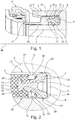
- your hydraulic disengagement assembly 31 includes a slave cylinder 1 with an annular, cylindrical housing 2 and an inner cylindrical guide tube 3. Between the housing 2 and the guide tube 3, an annular pressure chamber 4 is formed, which is connected to a hydraulic channel, not shown.
- the sealing ring 6 has a Y-shaped profile.
- the sealing ring 6 accordingly has a sealing lip 7, which rests against the cylindrical outer surface of the housing 2 and a further sealing lip 8, on the cylindrical inner surface the inner guide tube 3 rests. In this case, these sealing lips 7, 8 V-shaped apart.
- the annular piston 5 is in the FIG. 1 shown in an end position in which it communicates with a projection 9 in a conventional manner with the disengagement assembly 31 in connection.
- the axis of rotation of the present disengagement arrangement 31 is designated by 19.
- the sealing ring 6 further comprises a sealing foot 10 and an adjoining sealing neck or sealing area 11 between the sealing foot 10 and the sealing lips 7, 8, which extends in the axial direction.
- the sealing foot 10 engages in a complementary to him formed recess 12 of the annular piston 5, which is in the pressure chamber 4 facing end portion of the annular piston 5.
- the sealing foot 10 comprises an outer annular groove 13 and an inner annular groove 14, engage in the corresponding undercuts 15, 16 of the recess 12 of the annular piston 5 in a conventional manner to connect the sealing ring 6 with its sealing foot 10 form-fitting manner with the annular piston 5. This fact is particularly clear from the FIG. 2 seen.
- an outer ring member 17 and an inner ring member 18 are provided for reinforcing and supporting the sealing ring 6, which surround the substantially axially extending sealing region 11 of the sealing ring 6 outside or inside.
- the outer ring member 17 and the inner ring member 18 are arranged and supported in the pressure chamber 4 and reduce the volume absorption and the hysteresis of the sealing ring 6 at a load.
- the sealing ring 6 is connected without play.
- the sealing region 11 of the sealing ring 6 passes through the space between the outer ring part 17 and the inner ring part 18, wherein the areas of the ring parts 17, 18 forming this space extend in each case starting from an axial region 20, 21 over an arcuate region 22, 23, like this FIG. 2 shows very clearly.
- the said space forms a form-fit between the sealing ring 6 and the outer ring member 17 and the inner ring member 18.
- the ring members 17, 18 are preferably made of a non-reinforced plastic material.
- the outer ring member 17 is located axially with its surface 24 on the surface 25 facing it of the annular piston 5 radially outside of the recess 12 at.
- the inner ring member 17 is located axially with its surface 26 on the surface 25 facing it of the annular piston 5 radially within the recess 12 at. In this way, it is achieved that the ring parts 17 and 18 are respectively supported axially on the annular piston 5 at a pressure build-up in the pressure chamber 4.
Landscapes
- Engineering & Computer Science (AREA)
- General Engineering & Computer Science (AREA)
- Mechanical Engineering (AREA)
- Hydraulic Clutches, Magnetic Clutches, Fluid Clutches, And Fluid Joints (AREA)
- Sealing With Elastic Sealing Lips (AREA)
Description
- Die vorliegende Erfindung betrifft einen Nehmerzylinder für eine hydraulische Ausrückanordnung zur Betätigung einer Kupplung. Dabei ist das hydraulische Ausrücksystem der Kupplung, bei der es sich insbesondere um eine Doppelkupplung handelt, deckelfest und konzentrisch angeordnet.
- Aus der
EP 01970589 B1 - Aus der Druckschrift
WO 00/06921 - Weitere Nehmerzylindern für hydraulische Ausrücksysteme sind aus der
DE 19949205 A1 und derFR 2772443 A1 - Die Aufgabe der vorliegenden Erfindung besteht darin, einen Nehmerzylinder für eine hydraulische Ausrückanordnung zur Betätigung einer Kupplung so auszugestalten, dass die Volumenaufnahme und die Hysterese des an dem Ringkolben vorgesehenen Dichtungsringes möglichst klein sind.
- Diese Aufgabe wird durch einen Nehmerzylinder mit den Merkmalen des Patentanspruches 1 gelöst.
- Demgemäß betrifft die vorliegende Erfindung einen Nehmerzylinder für eine Ausrückanordnung zur Betätigung einer Kupplung mit einem zylindrischen Gehäuse und einem konzentrisch dazu angeordneten und radial beabstandeten, zylindrischen Führungsrohr, die zwischen sich eine ringförmige Druckkammer bilden, in der ein Ringkolben axial verschiebbar angeordnet ist. Der Ringkolben weist dabei an seiner der Druckkammer zugewandten Seite einen Dichtungsring auf. Der Dichtungsring umfasst einen axial verlaufenden Dichtungshals bzw. Dichtungsbereich. Ein äußeres Ringteil ist zwischen der Außenseite des Dichtungsbereiches und der zylindrischen Innenfläche des Gehäuses angeordnet. Ferner ist ein inneres Ringteil zwischen der Innenseite des Dichtungsbereiches und der zylindrischen Außenfläche des Führungsrohres vorgesehen. Dies hat den Vorteil, dass sich der Dichtungsbereich bei einer Druckbeaufschlagung des Dichtungsringes über das äußere Ringteil an der Innenfläche des Gehäuses und über das innere Ringteil an der Außenseite des Führungsrohres abstützt. Durch diese Abstützung wird vorteilhafter Weise erreicht, dass bei einer Belastung des Dichtungsringes die Volumenvergrößerung des Dichtungsringes extrem klein ist. Zudem wird dadurch erreicht, dass die Hystereseerscheinungen bei einer solchen und gleichzeitig einer spielfreien Anbindung der Dichtung an den Kolben gewährleistet ist.
- Der Dichtungsring weist ein Y-förmiges Profil auf, das einen Dichtungsfuß, den axial daran anschließenden Dichtungsbereich und an diesen anschließend, eine äußere Dichtlippe und eine innere Dichtlippe umfasst. Die Dichtlippen laufen dabei V-förmig auseinander. Die äußere Dichtlippe liegt an der zylindrischen Innenfläche des Gehäuses und die innere Dichtlippe liegt an der zylindrischen Außenfläche des Führungsrohres an. Dadurch wird bei einer Belastung des Dichtungsringes eine besonders dichte Verbindung zwischen den Dichtlippen und dem Gehäuse bzw. dem Führungsrohr sichergestellt.
- Der Dichtungsfuß des Dichtungsringes wird formschlüssig und dicht in einer komplementär zu ihm ausgebildeten Ausnehmung des Ringkolbens gehalten, wobei die Ausnehmung zweckmäßigerweise Hinterschneidungen aufweist.
- Ferner wird eine besonders gute Abdichtung bei einer Belastung erzielt, wenn sich der genannte Dichtungsbereich ausgehend von dem Dichtungsfuß des Dichtungsringes jeweils bogenförmig nach außen zu der äußeren Dichtlippe bzw. nach innen zu der inneren Dichtlippe vorzugsweise erweitert und wenn sich dementsprechend vorzugsweise auch das äußere Ringteil innenseitig, ausgehend von der Seite des Ringkolbens im Dichtungsbereich des Dichtungsringes bogenförmig nach außen erweitert und sich das innere Ringteil außenseitig, ausgehend von der Seite des Ringkolbens im Dichtungsbereich des Dichtungsringes bogenförmig nach innen erweitert. Auf diese Wse wird der Dichtungsring in dem Dichtungsbereich formschlüssig zwischen dem äußeren Ringteil und dem inneren Ringteil gehalten.
- Im Belastungsfall ist es besonders vorteilhaft, wenn sich die einander zugewandten Flächen des äußeren Ringteiles, des inneren Ringteiles und des Ringkolbens jeweils axial aneinander abstützen.
- Bei einer bevorzugten Ausführungsform liegen die dem Ringkolben zugewandte Fläche des äußeren Ringteiles radial außerhalb der Ausnehmung an dem Ringkolben und die dem Ringkolben zugewandte Fläche des inneren Ringteiles radial innerhalb der Ausnehmung an dem Ringkolben an.
- Vorteilhafter Weise bestehen die Ringteile aus einem nicht verstärkten Kunststoffmaterial.
- Im Folgenden werden die Erfindung und deren Ausgestaltungen im Zusammenhang mit den Figuren näher erläutert. Es zeigen:
- Figur 1
- einen Teilschnitt durch ein den erfindungsgemäßen Nehmerzylinder aufweisendes hydraulisches Ausrücksystem und
- Figur 2
- eine vergrößerte Darstellung des Ringkolbens und des Dichtungsringes.
- Gemäß
Figur 1 umfasst deine hydraulische Ausrückanordnung 31 einen Nehmerzylinder 1 mit einem ringförmigen, zylindrischen Gehäuse 2 und einem inneren zylindrischen Führungsrohr 3. Zwischen dem Gehäuse 2 und dem Führungsrohr 3 ist eine ringförmige Druckkammer 4 ausgebildet, die mit einem nicht näher dargestellten Hydraulikkanal verbunden ist. In der Druckkammer 4 befindet sich ein axial verschiebbarer Ringkolben 5, an dem ein Dichtungsring 6 formschlüssig befestigt ist. Vorzugsweise weist der Dichtungsring 6 ein Y-förmiges Profil auf. Der Dichtungsring 6 besitzt demgemäß eine Dichtlippe 7, die an der zylindrischen Außenfläche des Gehäuses 2 anliegt und eine weitere Dichtlippe 8, die an der zylindrischen Innenfläche des inneren Führungsrohres 3 anliegt. Dabei laufen diese Dichtlippen 7, 8 V-förmig auseinander. Der Ringkolben 5 ist in derFigur 1 in einer Endlage dargestellt, in der er mit einem Vorsprung 9 in an sich bekannter Weise mit der Ausrückanordnung 31 in Verbindung steht. Die Rotationsachse der vorliegenden Ausrückanordnung 31 ist mit 19 bezeichnet. - Der Dichtungsring 6 umfasst ferner einen Dichtungsfuß 10 sowie einen daran anschließenden Dichtungshals bzw. Dichtungsbereich 11 zwischen dem Dichtungsfuß 10 und den Dichtlippen 7, 8, der in axialer Richtung verläuft. Der Dichtungsfuß 10 greift in eine zu ihm komplementär ausgebildete Ausnehmung 12 des Ringkolbens 5 ein, die sich in dem der Druckkammer 4 zugewandten Endbereich des Ringkolbens 5 befindet. Der Dichtungsfuß 10 umfasst eine äußere Ringnut 13 sowie eine innere Ringnut 14, in die korrespondierende Hinterschneidungen 15, 16 der Ausnehmung 12 des Ringkolbens 5 in an sich bekannter Weise eingreifen, um den Dichtungsring 6 mit seinem Dichtungsfuß 10 formschlüssig mit dem Ringkolben 5 zu verbinden. Dieser Sachverhalt ist besonders deutlich aus der
Figur 2 ersichtlich. - Erfindungsgemäß sind zur Verstärkung und Abstützung des Dichtungsringes 6 ein äußeres Ringteil 17 und ein inneres Ringteil 18 vorgesehen, die den im Wesentlichen axial verlaufenden Dichtungsbereich 11 des Dichtungsringes 6 außen- bzw. innenseitig umgeben. Das äußere Ringteil 17 und das innere Ringteil 18 sind in der Druckkammer 4 angeordnet und abgestützt und reduzieren die Volumenaufnahme und die Hysterese des Dichtungsringes 6 bei einer Belastung. Der Dichtungsring 6 ist dabei spielfrei angebunden. Der Dichtungsbereich 11 des Dichtungsringes 6 durchgreift den Raum zwischen dem äußeren Ringteil 17 und dem inneren Ringteil 18, wobei sich die diesen Raum bildenden Bereiche der Ringteile 17, 18 jeweils ausgehend von einem axialen Bereich 20, 21 über einen bogenförmigen Bereich 22, 23 erweitern, wie dies die
Figur 2 besonders deutlich zeigt. Der genannte Raum bildet einen Form-schluss zwischen dem Dichtungsring 6 und den äußeren Ringteil 17 sowie dem inneren Ring-teil 18. Die Ringteile 17, 18 bestehen vorzugsweise aus einem nicht verstärkten Kunststoff-material. - Das äußere Ringteil 17 liegt axial mit seiner Fläche 24 an der ihm zugewandten Fläche 25 des Ringkolbens 5 radial außerhalb der Ausnehmung 12 an. Das inner Ringteil 17 liegt axial mit seiner Fläche 26 an der ihm zugewandten Fläche 25 des Ringkolbens 5 radial innerhalb der Ausnehmung 12 an. Auf diese Weise wird erreicht, dass sich die Ringteile 17 und 18 bei einem Druckaufbau in der Druckkammer 4 jeweils axial an dem Ringkolben 5 abstützen.
- Wenn in der Druckkammer 4 ein Druck aufgebaut wird, stützen sich bei einer Druckbeaufschlagung des Dichtungsringes 6 das äußere Ringteil 17 an der zylindrischen Innenfläche 27 des Gehäuses 2 und das innere Ringteil 18 an der zylindrischen Außenfläche 28 des inneren Führungsrohres 3 ab. Der Dichtungsring 6 wird dabei durch das äußere Ringteil 17 und das innere Ringteil 18 gestützt. Die Dichtungsflächen 29, 30 zwischen der Dichtlippe 7 und der Innenfläche 27 des Gehäuses 2 bzw. zwischen der Dichtlippe 8 und der Außenfläche 28 des Führungsrohres 3, bewirken eine Abdichtung der Druckkammer 4.
-
- 1
- Nehmerzylinder
- 2
- Gehäuse
- 3
- Führungsrohr
- 4
- Druckkammer
- 5
- Ringkolben
- 6
- Dichtungsring
- 7
- Dichtlippe
- 8
- Dichtlippe
- 9
- Vorsprung
- 10
- Dichtungsfuß
- 11
- Dichtungsbereich
- 12
- Ausnehmung
- 13
- äußere Ringnut
- 14
- innere Ringnut
- 15
- Hinterschneidung
- 16
- Hinterschneidung
- 17
- äußeres Ringteil
- 18
- inneres Ringteil
- 19
- Rotationsachse
- 20
- Bereich
- 21
- Bereich
- 22
- bogenförmiger Bereich
- 23
- bogenförmiger Bereich
- 24
- Fläche
- 25
- Fläche
- 26
- Fläche I
- 27
- Innenfläche
- 28
- Außenfläche
- 29
- Dichtungsfläche
- 30
- Dichtungsfläche
- 31
- Ausrückanordnung
Claims (8)
- Nehmerzylinder für eine hydraulische Ausrückanordnung (31) zur Betätigung einer Kupplung, mit einem zylindrischen Gehäuse (1) und einem konzentrisch dazu angeordneten und radial beabstandeten, zylindrischen Führungsrohr (3), die zwischen sich eine ringförmige Druckkammer (4) bilden, in der ein Ringkolben (5) axial verschiebbar angeordnet ist, wobei der Ringkolben (5) an seiner der Druckkammer (4) zugewandten Seite einen Dichtungsring (6) aufweist, wobei der Dichtungsring (6) einen Dichtungsbereich (11) und ein Y-förmiges Profil aufweist, das einen Dichtungsfuß (10), den axial daran anschließenden Dichtungsbereich (11) und an diesen anschließend, eine äußere Dichtlippe (7) und eine innere Dichtlippe (8) umfasst, die V-förmig auseinanderlaufen, wobei die äußere Dichtlippe (7) an der zylindrischen Innenfläche (27) des Gehäuses (1) und die innere Dichtlippe (8) an der zylindrischen Außenfläche (28) des Führungsrohres (3) anliegen, und ein äußeres Ringteil (17) zwischen der Außenseite des Dichtungsbereiches (11) und der zylindrischen Innenfläche (27) des Gehäuses (1) und ein inneres Ringteil (18) zwischen der Innenseite des Dichtungsbereiches (11) und der zylindrischen Außenfläche (28) des Führungsrohres (3) derart vorgesehen sind, dass sich der Dichtungsbereich (11) bei einer Druckbeaufschlagung des Dichtungsringes (6) über das äußere Ringteil (17) an der Innenfläche (27) des Gehäuses (1) und über das innere Ringteil (18) an der Außenfläche (28) des Führungsrohres (3) abstützen, dadurch gekennzeichnet, dass der Dichtungsfuß (10) formschlüssig und dicht in einer komplementär zu ihm ausgebildeten Ausnehmung (12) des Ringkolbens (5) gehalten ist.
- Nehmerzylinder nach Anspruch 1, dadurch gekennzeichnet, dass sich der Dichtungsbereich (11) ausgehend von dem Dichtungsfuß (10) jeweils bogenförmig nach außen zu der äußeren Dichtlippe (7) bzw. nach innen zu der inneren Dichtlippe (8) erweitert.
- Nehmerzylinder nach Anspruch 1 oder 2, dadurch gekennzeichnet, dass der Dichtungsbereich (11) ausgehend von dem Dichtungsfuß (10) zunächst jeweils axial verläuft und sich anschließend bogenförmig nach außen zu der äußeren Dichtlippe (7) bzw. nach innen zu der inneren Dichtlippe (8) erweitert.
- Nehmerzylinder nach einem der Ansprüche 1 bis 3, dadurch gekennzeichnet, dass sich das äußere Ringteil (17) innenseitig, ausgehend von der Seite des Ringkolbens bogenförmig nach außen erweitert und dass sich das innere Ringteil (18) außenseitig, bogenförmig nach innen erweitert, sodass der Dichtungsring (6) mit seinem Dichtungsbereich (11) formschlüssig zwischen dem äußeren Ringteil (17) und dem inneren Ringteil (18) gehalten ist.
- Nehmerzylinder nach einem der Ansprüche 1 bis 4, dadurch gekennzeichnet, dass die Ausnehmung (12) Hinterschneidungen (15, 16) aufweist.
- Nehmerzylinder nach einem der Ansprüche 1 bis 5, dadurch gekennzeichnet, dass sich das äußere Ringteil (17) und das innere Ringteil (18) jeweils axial an dem Ringkolben (5) abstützen.
- Nehmerzylinder nach einem der Ansprüche 1 bis 6, dadurch gekennzeichnet, dass die dem Ringkolben (5) zugewandte Seite des äußeren Ringteiles (17) radial außerhalb der Ausnehmung (12) an dem Ringkolben (5) und die dem Ringkolben (5) zugewandte Seite des inneren Ringteiles (18) radial innerhalb der Ausnehmung (12) an dem Ringkolben (6) anliegen.
- Nehmerzylinder nach einem der Ansprüche 1 bis 7, dadurch gekennzeichnet, dass die Ringteile (17, 18) aus einem nicht verstärkten Kunststoffmaterial bestehen.
Applications Claiming Priority (2)
| Application Number | Priority Date | Filing Date | Title |
|---|---|---|---|
| DE102012213656 | 2012-08-02 | ||
| PCT/DE2013/200071 WO2014019580A1 (de) | 2012-08-02 | 2013-07-23 | Nehmerzylinder für eine hydraulische ausrückanordnung zur betätigung einer kupplung |
Publications (2)
| Publication Number | Publication Date |
|---|---|
| EP2880329A1 EP2880329A1 (de) | 2015-06-10 |
| EP2880329B1 true EP2880329B1 (de) | 2017-04-19 |
Family
ID=49080627
Family Applications (1)
| Application Number | Title | Priority Date | Filing Date |
|---|---|---|---|
| EP13753556.3A Active EP2880329B1 (de) | 2012-08-02 | 2013-07-23 | Nehmerzylinder für eine hydraulische ausrückanordnung zur betätigung einer kupplung |
Country Status (5)
| Country | Link |
|---|---|
| EP (1) | EP2880329B1 (de) |
| JP (1) | JP6385346B2 (de) |
| CN (1) | CN104620007B (de) |
| DE (2) | DE102013214370A1 (de) |
| WO (1) | WO2014019580A1 (de) |
Families Citing this family (11)
| Publication number | Priority date | Publication date | Assignee | Title |
|---|---|---|---|---|
| DE102015201332B4 (de) * | 2014-02-24 | 2025-05-22 | Schaeffler Technologies AG & Co. KG | Kolben-Zylindereinheit |
| TWI892600B (zh) * | 2014-04-17 | 2025-08-01 | 新加坡商肯發系統私人有限公司 | 用於密封地結合相對流體導管端口之環形襯墊及形成一高純度流體接頭之方法 |
| DE102015204676B4 (de) | 2015-03-16 | 2025-05-22 | Schaeffler Technologies AG & Co. KG | Anordnung aus Ringkolben und Nutdichtring für Nehmerzylinder von Kupplungsbetätigungsvorrichtungen |
| DE102018108655A1 (de) * | 2017-05-12 | 2018-11-15 | Schaeffler Technologies AG & Co. KG | Kolbenaufbau für einen Nehmerzylinder mit umgreifender Dichtung |
| DE102017110328B4 (de) | 2017-05-12 | 2022-10-06 | Schaeffler Technologies AG & Co. KG | Kolbenbaugruppe für einen Nehmerzylinder mit umgreifender Dichtung und Hülse und Montageverfahren für Kolbenbaugruppe |
| DE102017119722B3 (de) * | 2017-08-29 | 2018-11-08 | Schaeffler Technologies AG & Co. KG | Kupplungsnehmerzylinder |
| CN111051723B (zh) * | 2017-09-01 | 2022-01-21 | 舍弗勒技术股份两合公司 | 离合器分离系统用活塞密封组件及离合器分离系统 |
| DE102018102449A1 (de) * | 2018-02-05 | 2019-08-08 | Schaeffler Technologies AG & Co. KG | Nehmerzylinder mit Kolben ausgebildet zur Verschleißreduzierung; Betätigungseinrichtung; sowie Kupplungssystem |
| DE102019101452A1 (de) * | 2019-01-21 | 2020-07-23 | Fte Automotive Gmbh | Zentralaktuator für eine hydraulische oder pneumatische Kupplungsbetätigung |
| DE102021101141B4 (de) * | 2021-01-20 | 2022-08-18 | Schaeffler Technologies AG & Co. KG | Abkoppelvorrichtung und Abkoppelsystem |
| DE102021206769B4 (de) * | 2021-06-29 | 2025-05-22 | Trelleborg Sealing Solutions Germany Gmbh | Rotationsdichtungsanordnung mit Rotationsdichtung und mit ölseitig angeordnetem Schaumring |
Family Cites Families (8)
| Publication number | Priority date | Publication date | Assignee | Title |
|---|---|---|---|---|
| DE3620539A1 (de) * | 1986-06-19 | 1987-12-23 | Busak & Luyken Gmbh & Co | Dichtung |
| SE464887B (sv) * | 1988-11-30 | 1991-06-24 | Volvo Hydraulik Ab | Anordning foer taetning mellan en cylindrisk mantelyta paa en kropp och en koaxiellt omgivande cylindrisk haalvaeggyta |
| FR2772443B1 (fr) * | 1997-12-11 | 2001-09-28 | Valeo | Recepteur hydraulique de commande d'embrayage notamment pour vehicule automobile |
| JPH10311350A (ja) * | 1997-05-09 | 1998-11-24 | Koyo Seiko Co Ltd | 油圧式クラッチ遮断装置 |
| US6196552B1 (en) * | 1998-06-08 | 2001-03-06 | Automotive Products (Usa), Inc. | Seal assembly for annular hydraulic cylinder |
| DE19981436D2 (de) | 1998-07-24 | 2001-07-12 | Luk Lamellen & Kupplungsbau | Dichtung für ein hydraulisch betätigtes Ausrücksystem |
| GB2344393B (en) * | 1998-10-15 | 2003-07-09 | Luk Lamellen & Kupplungsbau | Hydraulic release system |
| DE102008009655A1 (de) * | 2007-03-12 | 2008-09-18 | Luk Lamellen Und Kupplungsbau Beteiligungs Kg | Nehmerzylinder |
-
2013
- 2013-07-23 DE DE102013214370.2A patent/DE102013214370A1/de not_active Withdrawn
- 2013-07-23 WO PCT/DE2013/200071 patent/WO2014019580A1/de not_active Ceased
- 2013-07-23 EP EP13753556.3A patent/EP2880329B1/de active Active
- 2013-07-23 JP JP2015524641A patent/JP6385346B2/ja active Active
- 2013-07-23 DE DE201311003824 patent/DE112013003824A5/de not_active Withdrawn
- 2013-07-23 CN CN201380038671.0A patent/CN104620007B/zh active Active
Non-Patent Citations (1)
| Title |
|---|
| None * |
Also Published As
| Publication number | Publication date |
|---|---|
| JP2015523522A (ja) | 2015-08-13 |
| WO2014019580A1 (de) | 2014-02-06 |
| CN104620007A (zh) | 2015-05-13 |
| JP6385346B2 (ja) | 2018-09-05 |
| DE112013003824A5 (de) | 2015-04-30 |
| CN104620007B (zh) | 2017-07-11 |
| DE102013214370A1 (de) | 2014-02-06 |
| EP2880329A1 (de) | 2015-06-10 |
Similar Documents
| Publication | Publication Date | Title |
|---|---|---|
| EP2880329A1 (de) | Nehmerzylinder für eine hydraulische ausrückanordnung zur betätigung einer kupplung | |
| EP1970589B1 (de) | Nehmerzylinder | |
| DE4129370C2 (de) | Hydraulisch betätigbarer Ausrücker mit Stützring und Stützschulter | |
| EP2739874B1 (de) | Nehmerzylinder | |
| EP2880330B1 (de) | Kolben-zylindereinheit eines hydraulischen systems | |
| EP2875252B1 (de) | Kolben-zylinder-anordnung, insbesondere für ein kupplungsbetätigungssystem in einem kraftfahrzeug | |
| DE102015201398A1 (de) | Dichtungsanordnung | |
| WO2008014768A2 (de) | Abgedichtetes wälzlager | |
| DE19523011A1 (de) | Hydraulische Ausrückvorrichtung für eine Reibungskupplung | |
| EP2280198B1 (de) | Verschlusseinheit für ein Kolben-Zylinderaggregat | |
| DE20380270U1 (de) | Hydraulisches System insbesondere für Kraftfahrzeuge | |
| DE102015202270A1 (de) | Planetenwälzgewindespindel (PWG) | |
| DE102007005690A1 (de) | Verschlusspaket für einen Schwingungsdämpfer und Schwingungsdämpfer mit einem solchen Verschlusspaket | |
| DE102013204745A1 (de) | Kolbenstangendichtung für einen hydraulischen Schwingungsdämpfer | |
| EP1162394B1 (de) | Dichtelement für hydraulische Kolben-Zylinder-Anordnungen | |
| DE102011087103A1 (de) | Geberzylinder | |
| DE102009054524A1 (de) | Dichtring für eine Kolbenpumpe | |
| DE212013000271U1 (de) | Dichtung für eine hydraulische Kolben-Zylinder-Anordnung | |
| DE102009038638A1 (de) | Geberzylinder mitt einem Wegsensor | |
| DE19724988A1 (de) | Ringkolbendichtung für ein hydraulisches Ausrücksystem | |
| DE102014217648A1 (de) | Nehmerzylinder | |
| DE102014208898A1 (de) | Nehmerzylinder für ein hydraulisches Ausrücksystem mit Kolbenzentrierung | |
| DE102018111760B4 (de) | Nehmerzylinder mit geteiltem Dichtringträger | |
| WO2018145691A1 (de) | Geberzylinder mit dichtelement | |
| EP2306040B1 (de) | Scheibenbremse und Führungsholm einer Scheibenbremse |
Legal Events
| Date | Code | Title | Description |
|---|---|---|---|
| PUAI | Public reference made under article 153(3) epc to a published international application that has entered the european phase |
Free format text: ORIGINAL CODE: 0009012 |
|
| 17P | Request for examination filed |
Effective date: 20150302 |
|
| AK | Designated contracting states |
Kind code of ref document: A1 Designated state(s): AL AT BE BG CH CY CZ DE DK EE ES FI FR GB GR HR HU IE IS IT LI LT LU LV MC MK MT NL NO PL PT RO RS SE SI SK SM TR |
|
| AX | Request for extension of the european patent |
Extension state: BA ME |
|
| DAX | Request for extension of the european patent (deleted) | ||
| GRAP | Despatch of communication of intention to grant a patent |
Free format text: ORIGINAL CODE: EPIDOSNIGR1 |
|
| INTG | Intention to grant announced |
Effective date: 20161208 |
|
| GRAS | Grant fee paid |
Free format text: ORIGINAL CODE: EPIDOSNIGR3 |
|
| GRAA | (expected) grant |
Free format text: ORIGINAL CODE: 0009210 |
|
| AK | Designated contracting states |
Kind code of ref document: B1 Designated state(s): AL AT BE BG CH CY CZ DE DK EE ES FI FR GB GR HR HU IE IS IT LI LT LU LV MC MK MT NL NO PL PT RO RS SE SI SK SM TR |
|
| REG | Reference to a national code |
Ref country code: GB Ref legal event code: FG4D Free format text: NOT ENGLISH |
|
| REG | Reference to a national code |
Ref country code: CH Ref legal event code: EP |
|
| REG | Reference to a national code |
Ref country code: AT Ref legal event code: REF Ref document number: 886272 Country of ref document: AT Kind code of ref document: T Effective date: 20170515 |
|
| REG | Reference to a national code |
Ref country code: IE Ref legal event code: FG4D Free format text: LANGUAGE OF EP DOCUMENT: GERMAN |
|
| REG | Reference to a national code |
Ref country code: DE Ref legal event code: R096 Ref document number: 502013007026 Country of ref document: DE |
|
| REG | Reference to a national code |
Ref country code: FR Ref legal event code: PLFP Year of fee payment: 5 |
|
| REG | Reference to a national code |
Ref country code: NL Ref legal event code: MP Effective date: 20170419 |
|
| REG | Reference to a national code |
Ref country code: LT Ref legal event code: MG4D |
|
| PG25 | Lapsed in a contracting state [announced via postgrant information from national office to epo] |
Ref country code: NL Free format text: LAPSE BECAUSE OF FAILURE TO SUBMIT A TRANSLATION OF THE DESCRIPTION OR TO PAY THE FEE WITHIN THE PRESCRIBED TIME-LIMIT Effective date: 20170419 |
|
| PG25 | Lapsed in a contracting state [announced via postgrant information from national office to epo] |
Ref country code: FI Free format text: LAPSE BECAUSE OF FAILURE TO SUBMIT A TRANSLATION OF THE DESCRIPTION OR TO PAY THE FEE WITHIN THE PRESCRIBED TIME-LIMIT Effective date: 20170419 Ref country code: LT Free format text: LAPSE BECAUSE OF FAILURE TO SUBMIT A TRANSLATION OF THE DESCRIPTION OR TO PAY THE FEE WITHIN THE PRESCRIBED TIME-LIMIT Effective date: 20170419 Ref country code: GR Free format text: LAPSE BECAUSE OF FAILURE TO SUBMIT A TRANSLATION OF THE DESCRIPTION OR TO PAY THE FEE WITHIN THE PRESCRIBED TIME-LIMIT Effective date: 20170720 Ref country code: NO Free format text: LAPSE BECAUSE OF FAILURE TO SUBMIT A TRANSLATION OF THE DESCRIPTION OR TO PAY THE FEE WITHIN THE PRESCRIBED TIME-LIMIT Effective date: 20170719 Ref country code: HR Free format text: LAPSE BECAUSE OF FAILURE TO SUBMIT A TRANSLATION OF THE DESCRIPTION OR TO PAY THE FEE WITHIN THE PRESCRIBED TIME-LIMIT Effective date: 20170419 Ref country code: ES Free format text: LAPSE BECAUSE OF FAILURE TO SUBMIT A TRANSLATION OF THE DESCRIPTION OR TO PAY THE FEE WITHIN THE PRESCRIBED TIME-LIMIT Effective date: 20170419 |
|
| PG25 | Lapsed in a contracting state [announced via postgrant information from national office to epo] |
Ref country code: SE Free format text: LAPSE BECAUSE OF FAILURE TO SUBMIT A TRANSLATION OF THE DESCRIPTION OR TO PAY THE FEE WITHIN THE PRESCRIBED TIME-LIMIT Effective date: 20170419 Ref country code: BG Free format text: LAPSE BECAUSE OF FAILURE TO SUBMIT A TRANSLATION OF THE DESCRIPTION OR TO PAY THE FEE WITHIN THE PRESCRIBED TIME-LIMIT Effective date: 20170719 Ref country code: IS Free format text: LAPSE BECAUSE OF FAILURE TO SUBMIT A TRANSLATION OF THE DESCRIPTION OR TO PAY THE FEE WITHIN THE PRESCRIBED TIME-LIMIT Effective date: 20170819 Ref country code: RS Free format text: LAPSE BECAUSE OF FAILURE TO SUBMIT A TRANSLATION OF THE DESCRIPTION OR TO PAY THE FEE WITHIN THE PRESCRIBED TIME-LIMIT Effective date: 20170419 Ref country code: PL Free format text: LAPSE BECAUSE OF FAILURE TO SUBMIT A TRANSLATION OF THE DESCRIPTION OR TO PAY THE FEE WITHIN THE PRESCRIBED TIME-LIMIT Effective date: 20170419 Ref country code: LV Free format text: LAPSE BECAUSE OF FAILURE TO SUBMIT A TRANSLATION OF THE DESCRIPTION OR TO PAY THE FEE WITHIN THE PRESCRIBED TIME-LIMIT Effective date: 20170419 |
|
| REG | Reference to a national code |
Ref country code: DE Ref legal event code: R097 Ref document number: 502013007026 Country of ref document: DE |
|
| PG25 | Lapsed in a contracting state [announced via postgrant information from national office to epo] |
Ref country code: CZ Free format text: LAPSE BECAUSE OF FAILURE TO SUBMIT A TRANSLATION OF THE DESCRIPTION OR TO PAY THE FEE WITHIN THE PRESCRIBED TIME-LIMIT Effective date: 20170419 Ref country code: DK Free format text: LAPSE BECAUSE OF FAILURE TO SUBMIT A TRANSLATION OF THE DESCRIPTION OR TO PAY THE FEE WITHIN THE PRESCRIBED TIME-LIMIT Effective date: 20170419 Ref country code: SK Free format text: LAPSE BECAUSE OF FAILURE TO SUBMIT A TRANSLATION OF THE DESCRIPTION OR TO PAY THE FEE WITHIN THE PRESCRIBED TIME-LIMIT Effective date: 20170419 Ref country code: RO Free format text: LAPSE BECAUSE OF FAILURE TO SUBMIT A TRANSLATION OF THE DESCRIPTION OR TO PAY THE FEE WITHIN THE PRESCRIBED TIME-LIMIT Effective date: 20170419 Ref country code: EE Free format text: LAPSE BECAUSE OF FAILURE TO SUBMIT A TRANSLATION OF THE DESCRIPTION OR TO PAY THE FEE WITHIN THE PRESCRIBED TIME-LIMIT Effective date: 20170419 |
|
| PLBE | No opposition filed within time limit |
Free format text: ORIGINAL CODE: 0009261 |
|
| STAA | Information on the status of an ep patent application or granted ep patent |
Free format text: STATUS: NO OPPOSITION FILED WITHIN TIME LIMIT |
|
| PG25 | Lapsed in a contracting state [announced via postgrant information from national office to epo] |
Ref country code: SM Free format text: LAPSE BECAUSE OF FAILURE TO SUBMIT A TRANSLATION OF THE DESCRIPTION OR TO PAY THE FEE WITHIN THE PRESCRIBED TIME-LIMIT Effective date: 20170419 Ref country code: IT Free format text: LAPSE BECAUSE OF FAILURE TO SUBMIT A TRANSLATION OF THE DESCRIPTION OR TO PAY THE FEE WITHIN THE PRESCRIBED TIME-LIMIT Effective date: 20170419 |
|
| REG | Reference to a national code |
Ref country code: CH Ref legal event code: PL |
|
| 26N | No opposition filed |
Effective date: 20180122 |
|
| GBPC | Gb: european patent ceased through non-payment of renewal fee |
Effective date: 20170723 |
|
| REG | Reference to a national code |
Ref country code: IE Ref legal event code: MM4A |
|
| PG25 | Lapsed in a contracting state [announced via postgrant information from national office to epo] |
Ref country code: LI Free format text: LAPSE BECAUSE OF NON-PAYMENT OF DUE FEES Effective date: 20170731 Ref country code: CH Free format text: LAPSE BECAUSE OF NON-PAYMENT OF DUE FEES Effective date: 20170731 Ref country code: IE Free format text: LAPSE BECAUSE OF NON-PAYMENT OF DUE FEES Effective date: 20170723 Ref country code: GB Free format text: LAPSE BECAUSE OF NON-PAYMENT OF DUE FEES Effective date: 20170723 |
|
| PG25 | Lapsed in a contracting state [announced via postgrant information from national office to epo] |
Ref country code: SI Free format text: LAPSE BECAUSE OF FAILURE TO SUBMIT A TRANSLATION OF THE DESCRIPTION OR TO PAY THE FEE WITHIN THE PRESCRIBED TIME-LIMIT Effective date: 20170419 |
|
| REG | Reference to a national code |
Ref country code: BE Ref legal event code: MM Effective date: 20170731 |
|
| PG25 | Lapsed in a contracting state [announced via postgrant information from national office to epo] |
Ref country code: LU Free format text: LAPSE BECAUSE OF NON-PAYMENT OF DUE FEES Effective date: 20170723 |
|
| REG | Reference to a national code |
Ref country code: FR Ref legal event code: PLFP Year of fee payment: 6 |
|
| PG25 | Lapsed in a contracting state [announced via postgrant information from national office to epo] |
Ref country code: BE Free format text: LAPSE BECAUSE OF NON-PAYMENT OF DUE FEES Effective date: 20170731 |
|
| PG25 | Lapsed in a contracting state [announced via postgrant information from national office to epo] |
Ref country code: MT Free format text: LAPSE BECAUSE OF FAILURE TO SUBMIT A TRANSLATION OF THE DESCRIPTION OR TO PAY THE FEE WITHIN THE PRESCRIBED TIME-LIMIT Effective date: 20170419 |
|
| PG25 | Lapsed in a contracting state [announced via postgrant information from national office to epo] |
Ref country code: MC Free format text: LAPSE BECAUSE OF FAILURE TO SUBMIT A TRANSLATION OF THE DESCRIPTION OR TO PAY THE FEE WITHIN THE PRESCRIBED TIME-LIMIT Effective date: 20170419 Ref country code: HU Free format text: LAPSE BECAUSE OF FAILURE TO SUBMIT A TRANSLATION OF THE DESCRIPTION OR TO PAY THE FEE WITHIN THE PRESCRIBED TIME-LIMIT; INVALID AB INITIO Effective date: 20130723 |
|
| REG | Reference to a national code |
Ref country code: AT Ref legal event code: MM01 Ref document number: 886272 Country of ref document: AT Kind code of ref document: T Effective date: 20180723 |
|
| PG25 | Lapsed in a contracting state [announced via postgrant information from national office to epo] |
Ref country code: CY Free format text: LAPSE BECAUSE OF FAILURE TO SUBMIT A TRANSLATION OF THE DESCRIPTION OR TO PAY THE FEE WITHIN THE PRESCRIBED TIME-LIMIT Effective date: 20170419 |
|
| PG25 | Lapsed in a contracting state [announced via postgrant information from national office to epo] |
Ref country code: MK Free format text: LAPSE BECAUSE OF FAILURE TO SUBMIT A TRANSLATION OF THE DESCRIPTION OR TO PAY THE FEE WITHIN THE PRESCRIBED TIME-LIMIT Effective date: 20170419 |
|
| PG25 | Lapsed in a contracting state [announced via postgrant information from national office to epo] |
Ref country code: AT Free format text: LAPSE BECAUSE OF NON-PAYMENT OF DUE FEES Effective date: 20180723 |
|
| PG25 | Lapsed in a contracting state [announced via postgrant information from national office to epo] |
Ref country code: TR Free format text: LAPSE BECAUSE OF FAILURE TO SUBMIT A TRANSLATION OF THE DESCRIPTION OR TO PAY THE FEE WITHIN THE PRESCRIBED TIME-LIMIT Effective date: 20170419 |
|
| PG25 | Lapsed in a contracting state [announced via postgrant information from national office to epo] |
Ref country code: PT Free format text: LAPSE BECAUSE OF FAILURE TO SUBMIT A TRANSLATION OF THE DESCRIPTION OR TO PAY THE FEE WITHIN THE PRESCRIBED TIME-LIMIT Effective date: 20170419 |
|
| PG25 | Lapsed in a contracting state [announced via postgrant information from national office to epo] |
Ref country code: AL Free format text: LAPSE BECAUSE OF FAILURE TO SUBMIT A TRANSLATION OF THE DESCRIPTION OR TO PAY THE FEE WITHIN THE PRESCRIBED TIME-LIMIT Effective date: 20170419 |
|
| P01 | Opt-out of the competence of the unified patent court (upc) registered |
Effective date: 20230523 |
|
| PGFP | Annual fee paid to national office [announced via postgrant information from national office to epo] |
Ref country code: DE Payment date: 20250919 Year of fee payment: 13 |
|
| PGFP | Annual fee paid to national office [announced via postgrant information from national office to epo] |
Ref country code: FR Payment date: 20250725 Year of fee payment: 13 |