EP2880385B1 - Appareil frigorifique avec bac d'évaporation - Google Patents
Appareil frigorifique avec bac d'évaporation Download PDFInfo
- Publication number
- EP2880385B1 EP2880385B1 EP13737271.0A EP13737271A EP2880385B1 EP 2880385 B1 EP2880385 B1 EP 2880385B1 EP 13737271 A EP13737271 A EP 13737271A EP 2880385 B1 EP2880385 B1 EP 2880385B1
- Authority
- EP
- European Patent Office
- Prior art keywords
- evaporation tray
- control unit
- current
- compressor motor
- compressor
- Prior art date
- Legal status (The legal status is an assumption and is not a legal conclusion. Google has not performed a legal analysis and makes no representation as to the accuracy of the status listed.)
- Active
Links
Images
Classifications
-
- F—MECHANICAL ENGINEERING; LIGHTING; HEATING; WEAPONS; BLASTING
- F25—REFRIGERATION OR COOLING; COMBINED HEATING AND REFRIGERATION SYSTEMS; HEAT PUMP SYSTEMS; MANUFACTURE OR STORAGE OF ICE; LIQUEFACTION SOLIDIFICATION OF GASES
- F25D—REFRIGERATORS; COLD ROOMS; ICE-BOXES; COOLING OR FREEZING APPARATUS NOT OTHERWISE PROVIDED FOR
- F25D21/00—Defrosting; Preventing frosting; Removing condensed or defrost water
- F25D21/14—Collecting or removing condensed and defrost water; Drip trays
-
- F—MECHANICAL ENGINEERING; LIGHTING; HEATING; WEAPONS; BLASTING
- F25—REFRIGERATION OR COOLING; COMBINED HEATING AND REFRIGERATION SYSTEMS; HEAT PUMP SYSTEMS; MANUFACTURE OR STORAGE OF ICE; LIQUEFACTION SOLIDIFICATION OF GASES
- F25B—REFRIGERATION MACHINES, PLANTS OR SYSTEMS; COMBINED HEATING AND REFRIGERATION SYSTEMS; HEAT PUMP SYSTEMS
- F25B49/00—Arrangement or mounting of control or safety devices
- F25B49/02—Arrangement or mounting of control or safety devices for compression type machines, plants or systems
- F25B49/022—Compressor control arrangements
-
- F—MECHANICAL ENGINEERING; LIGHTING; HEATING; WEAPONS; BLASTING
- F25—REFRIGERATION OR COOLING; COMBINED HEATING AND REFRIGERATION SYSTEMS; HEAT PUMP SYSTEMS; MANUFACTURE OR STORAGE OF ICE; LIQUEFACTION SOLIDIFICATION OF GASES
- F25B—REFRIGERATION MACHINES, PLANTS OR SYSTEMS; COMBINED HEATING AND REFRIGERATION SYSTEMS; HEAT PUMP SYSTEMS
- F25B49/00—Arrangement or mounting of control or safety devices
- F25B49/02—Arrangement or mounting of control or safety devices for compression type machines, plants or systems
- F25B49/025—Motor control arrangements
-
- F—MECHANICAL ENGINEERING; LIGHTING; HEATING; WEAPONS; BLASTING
- F25—REFRIGERATION OR COOLING; COMBINED HEATING AND REFRIGERATION SYSTEMS; HEAT PUMP SYSTEMS; MANUFACTURE OR STORAGE OF ICE; LIQUEFACTION SOLIDIFICATION OF GASES
- F25D—REFRIGERATORS; COLD ROOMS; ICE-BOXES; COOLING OR FREEZING APPARATUS NOT OTHERWISE PROVIDED FOR
- F25D2321/00—Details or arrangements for defrosting; Preventing frosting; Removing condensed or defrost water, not provided for in other groups of this subclass
- F25D2321/14—Collecting condense or defrost water; Removing condense or defrost water
- F25D2321/141—Removal by evaporation
- F25D2321/1411—Removal by evaporation using compressor heat
Definitions
- the present invention relates to a refrigeration appliance, in particular a household refrigeration appliance such as a refrigerator or freezer, with an evaporation tray for evaporating condensate derived from a storage chamber of the device and a compressor through the waste heat, the evaporation tray is heated.
- a refrigeration appliance in particular a household refrigeration appliance such as a refrigerator or freezer, with an evaporation tray for evaporating condensate derived from a storage chamber of the device and a compressor through the waste heat, the evaporation tray is heated.
- a refrigerator with evaporation tray and a variable speed compressor is described.
- the compressor can be switched between two operating modes, which differ in their speed and consequently also in the efficiency of refrigeration. While at low water level in the evaporation tray, the compressor should operate in highly efficient mode of operation, if the water level in the evaporation tray is critically high, it can be switched to the less efficient mode to produce more waste heat and reduce water in the evaporator bowl Evaporate evaporation tray faster.
- Object of the present invention is to provide a refrigeration device with evaporation tray, in which, if necessary, at any time to provide heat for promoting evaporation in the evaporation tray, without the need for its own heating device is required.
- control unit in a refrigeration appliance, in particular a domestic refrigeration appliance, with at least one storage chamber, an evaporation tray for evaporating condensate discharged from the storage chamber, a compressor motor arranged in thermal contact with the evaporation tray, and a control unit for supplying the compressor motor with power between a driving mode in which it supplies a current suitable for driving rotation of the compressor motor by energizing various windings of the compressor motor in a first order, and a heating operation mode in which it energizes in a second order different from the first order provides unsuitable current for driving the rotation, that is, a current that flows though the compressor motor and there releases Joule heat, but does not drive rotation.
- such an unsuitable current for driving a rotation may be a direct current to which a single winding of the compressor motor is applied.
- thermal load is distributed to different windings of the compressor motor.
- control unit comprises an inverter.
- the windings of the compressor motor are connected to the terminals so as to generate a magnetic field rotating in a first direction when the terminals are energized in the first order, and the armature of the motor starts to rotate by trying to align with the rotating field.
- the second order may then be suitably chosen such that a magnetic field rotating with an alternating sense of rotation or an oscillating magnetic field is generated.
- the control unit should expediently be set up to estimate the heat demand of the evaporation tray and to select between the drive operating mode and the heating operating mode on the basis of the estimated heat requirement.
- control unit can be connected to a water level sensor arranged on the evaporation tray.
- control unit can also be connected to a door opening sensor to estimate when and to what extent fresh and moist ambient air enters the storage chamber.
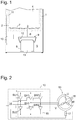
- FIG. 1 shown domestic refrigeration appliance, here a refrigerator has in a usual way a heat-insulating housing with a body 1 and a lying outside the cutting plane of the figure door, which defines a storage chamber 3 together with the body 1.
- the storage chamber 3 is cooled here by a coldwall evaporator 4 arranged on its rear wall 2 between an inner container of the body 1 and an insulating foam layer surrounding it, but it should be immediately obvious to the person skilled in the art that the features of the invention explained below are also in connection with any other types of evaporators, in particular a Nofrost evaporator, are applicable. Also conceivable is the application to a Nofrost freezer, since this, at least in a defrosting phase of its evaporator, also releases condensation.
- a collecting channel 7 extends at the foot of the rear wall of the storage chamber 3 which is cooled by the evaporator 4 and collects condensation water which condenses on the region of the inner container cooled by the evaporator 4 and flows downwards there.
- a pipeline 8 leads from the lowest point of the gutter 7 through the insulating foam layer through to an evaporation tray 9, which is mounted in a machine room 5 on a housing of a compressor 6, to be heated by waste heat of the compressor, in particular its drive motor.
- a corresponding pipeline could emanate from the bottom of a chamber receiving the evaporator.
- the compressor 6 is part of a refrigerant circuit in a customary and therefore not shown here in a figure, in which a pressure connection of the compressor 6 in a row, one behind the other. Condenser mounted outside on the rear wall 2, a throttle and the evaporator 4 are connected. An outlet of the evaporator 4 is in turn connected to a suction port of the compressor 6.
- An electronic control unit 10 comprises a microprocessor or microcontroller which is connected to a temperature sensor 11 arranged on the storage chamber 3 in order to control the operation of the compressor 6 on the basis of the temperature of the storage chamber 3.
- the control unit 10 is also adapted to estimate the amount of heat needed by the evaporation tray 9 to evaporate the condensation water flowing in it fast enough so that the evaporation tray 9 does not overflow.
- this can be a water level sensor 12, such as a float switch, be arranged in the evaporation tray 9, and the control unit 10 detects a heat demand of the evaporation tray 9 when the water level sensor 12 touches the water in the shell 9, or no heat demand when Water level below the water level sensor 12 is located.
- the control unit 10 can conclude the rate at which precipitates moisture at the evaporator 4, which later in the Evaporative shell 9 will land.
- the detection of the amount of heat energy used during defrosting allows an estimate of the amount of water thawed thereby and flowing into the evaporation tray 9. Such a detection may in particular be based on a measurement of the duration of the defrosting process.
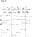
- Fig. 2 shows a block diagram of the control unit 10 and its driven by the motor 13 of the compressor 6.
- a microprocessor 14 controls six switches SU1, SV1, SW1, SU2, SV2, SW2 an inverter 15, each of which the switches SU1, SV1, SW1 between a positive supply potential (+) and a terminal or phase U, V or W of the motor 13 are arranged, and the switches SU2, SV2, SW2 respectively between one of these three terminals or phases and a negative supply potential (-) are arranged.
- the switches may, in a manner known per se, be IGBTs with a freewheeling diode or MOSFETs connected in parallel.
- the microprocessor 14 can with the above-mentioned, with the sensors 11, 12th be connected microprocessor identical, or it may be a second, responsible only for the sequence control of the motor 13 microprocessor. In the latter case, the two microprocessors will usually be mounted separately from each other, one in the vicinity of a user interface whose inputs it processes, the other 14 adjacent to the motor 13 controlled by it.
- Three stator windings 16 of the motor 13 are arranged here in a star connection between the phases U, V, W. It will be obvious to a person skilled in the art that a triangular circuit is also suitable, or that the number of phases and windings can also be greater than three.
- the microprocessor 14 In the drive mode of operation, the microprocessor 14 cyclically recurrently generates various switching states over time t, here six, which are in Fig. 3 with a, b, ..., f are designated.
- Fig. 3 shows for each of the switching states a to f, the state of the switches of the inverter 15 and the resulting voltages at the terminals U, V, W of the motor 13.
- state a the switches SU1, SW1 are closed.
- the switches SU2, SW2, SV1 are open and the switch SV2 is pulsed open and closed.
- the duty cycle of the switch SV2 current flows through the terminals U, V and V, W of the motor 13, and the resulting magnetic fields of the stator windings 16 are superimposed to a space vector u a .
- the switches SV2, SW2 are open, SU2, SV1, SW1 are closed and SU1 is pulse-width-modulated; accordingly, current flows through the terminals U; V and U, W, resulting in a space vector u b which is rotated counterclockwise by 60 ° to u a .
- the states closed, open, pulse width modulated the switch for the states c, d, e, f, as well as the resulting current distributions in the stator windings 16 and room pointer can from Fig. 3 be read and need not be explained in detail here. It is essential that the sequence of states a, b,..., F, a results in a continuous space-hand rotation of 360 °.
- the frequency with which the states a to f follow each other must be adapted to the rotational frequency of the armature. It may for example be controlled by means of a Hall sensor 17, which is arranged on the motor 13 and the field is exposed by the rotating armature, or a sensorless position detection.
- control unit 10 can energize the connection terminals U, V, W of the motor 13 in the heating operating mode.
- One possibility is, for example, to maintain one of the switching states a to f for the entire duration of the heating operation mode.
- the current on the terminal V is twice as high as at the terminals U, W, and accordingly, the heat development is distributed unevenly on the stator windings 16. Therefore, in this case, the duty cycle must be limited so that overheating of the most stressed stator winding 16 is excluded.
- a second possibility is to energize the connection terminals U, V, W so that an oscillating space vector is obtained instead of a rotating space vector.
- This is possible, for example, by periodically switching between the states a and d. If the switching frequency between the two states is high, then the duration of, for example, the state a is not sufficient to bring the rotor into a stable equilibrium position corresponding to the space vector u a , and any rotation of the rotor that has already begun is immediately decelerated again in state d, so that the rotor trembles at most slightly, but no rotation gets going. If the switching frequency is so low that a stable equilibrium position is reached in the state a, then this corresponds to a labile equilibrium in the state d, so that in turn no rotation starts.
- the distribution of the heating power to the stator windings 16 in this embodiment is the same as in the first considered case in which the switching state a is maintained throughout the heating operation. However, since the armature is not rotated, it is possible to occasionally switch from pair of states a, d to another pair such as b, e or c, f so as to distribute the heating power more uniformly to the windings.
- a, b, c three switching states which follow one another in the operating mode of operation alternate cyclically, for example the states a, b, c.
- another of the three terminals U, V, W is twice the current, so that the heating power is evenly distributed to all the stator windings 16.
- the states a, b, c successive turn by 120 °, but when the state c again followed by a, this in turn results in a decelerating torque on the armature, so that no rotation is initiated.
- the motor 13 thus generates heat only without performing mechanical work. Therefore, the water in the evaporation tray 9 can be evaporated quickly, even and especially when the storage chamber 3 has no refrigeration demand.
Landscapes
- Engineering & Computer Science (AREA)
- Physics & Mathematics (AREA)
- Mechanical Engineering (AREA)
- Thermal Sciences (AREA)
- General Engineering & Computer Science (AREA)
- Chemical & Material Sciences (AREA)
- Combustion & Propulsion (AREA)
- Removal Of Water From Condensation And Defrosting (AREA)
- Compressor (AREA)
- Control Of Motors That Do Not Use Commutators (AREA)
Claims (5)
- Appareil frigorifique, en particulier appareil frigorifique ménager, avec au moins une chambre de stockage (3), un bac d'évaporation (9) pour l'évaporation de l'eau de condensation issue de la chambre de stockage (3), un moteur de compresseur (13) disposé en contact thermique avec le bac d'évaporation (9) et une unité de commande (10) pour l'alimentation du moteur de compresseur (13) en courant électrique, dans lequel l'unité de commande (10) est commutable entre un mode d'exploitation de l'entraînement, dans lequel elle fournit un courant électrique approprié afin d'entraîner une rotation du moteur de compresseur (13), et un mode d'exploitation chauffant, dans lequel elle fournit un courant électrique inapproprié afin d'entraîner la rotation, dans lequel le moteur de compresseur (13) présente au moins trois bornes de raccordement (U, V, W), à alimenter en courant électrique selon un premier ordre afin d'actionner une rotation du moteur de compresseur (13) dans un sens de travail, et caractérisé en ce que l'unité de commande (10) est aménagée afin d'alimenter, en mode d'exploitation chauffant, les bornes de raccordement (U, V, W) selon un deuxième ordre différent du premier ordre.
- Appareil frigorifique selon la revendication 1, caractérisé en ce que l'unité de commande (10) englobe un convertisseur (15).
- Appareil frigorifique selon la revendication 1 ou 2, caractérisé en ce que les bobinages (16) du moteur de compresseur (13) sont reliés de telle sorte aux bornes de connexion (U, V, W) qu'ils génèrent, lors de l'alimentation en courant électrique des bornes de raccordement (U, V, W) selon le premier ordre, un champ magnétique assorti d'un premier sens de rotation, et en ce que le deuxième ordre est sélectionné de sorte qu'un champ magnétique assorti d'un sens de rotation variable ou un champ magnétique oscillant est généré.
- Appareil frigorifique selon l'une des revendications précédentes, caractérisé en ce que l'unité de commande (10) est aménagée afin d'estimer le besoin calorifique du bac d'évaporation (9) et de choisir parmi le mode d'exploitation de l'entraînement et le mode d'exploitation chauffant en fonction du besoin calorifique estimé.
- Appareil frigorifique selon l'une des revendications précédentes, caractérisé en ce que l'unité de commande (10) est reliée à un capteur de niveau d'eau (12) disposé sur le bac d'évaporation (9).
Applications Claiming Priority (2)
| Application Number | Priority Date | Filing Date | Title |
|---|---|---|---|
| DE102012213468.9A DE102012213468A1 (de) | 2012-07-31 | 2012-07-31 | Kältegerät mit Verdunstungsschale |
| PCT/EP2013/065062 WO2014019850A1 (fr) | 2012-07-31 | 2013-07-17 | Appareil frigorifique avec bac d'évaporation |
Publications (2)
| Publication Number | Publication Date |
|---|---|
| EP2880385A1 EP2880385A1 (fr) | 2015-06-10 |
| EP2880385B1 true EP2880385B1 (fr) | 2018-08-15 |
Family
ID=48793271
Family Applications (1)
| Application Number | Title | Priority Date | Filing Date |
|---|---|---|---|
| EP13737271.0A Active EP2880385B1 (fr) | 2012-07-31 | 2013-07-17 | Appareil frigorifique avec bac d'évaporation |
Country Status (4)
| Country | Link |
|---|---|
| EP (1) | EP2880385B1 (fr) |
| CN (1) | CN104508409B (fr) |
| DE (1) | DE102012213468A1 (fr) |
| WO (1) | WO2014019850A1 (fr) |
Families Citing this family (4)
| Publication number | Priority date | Publication date | Assignee | Title |
|---|---|---|---|---|
| DE102019118784A1 (de) * | 2019-05-29 | 2020-12-03 | Liebherr-Hausgeräte Ochsenhausen GmbH | Kühl- und/oder Gefriergerät |
| EP3745054B1 (fr) | 2019-05-29 | 2022-11-23 | Liebherr-Hausgeräte Ochsenhausen GmbH | Appareil de refroidissement et/ou de congélation |
| CN111884553A (zh) * | 2020-08-04 | 2020-11-03 | 儒竞艾默生环境优化技术(上海)有限公司 | 压缩机预加热的电流矢量控制方法、介质、设备及系统 |
| DE102023126020A1 (de) * | 2023-07-11 | 2025-01-16 | Liebherr-Hausgeräte Ochsenhausen GmbH | Kühl- und/oder Gefriergerät |
Family Cites Families (9)
| Publication number | Priority date | Publication date | Assignee | Title |
|---|---|---|---|---|
| JP3083959B2 (ja) * | 1994-07-25 | 2000-09-04 | シャープ株式会社 | 冷蔵庫 |
| US6629429B1 (en) * | 1999-03-12 | 2003-10-07 | Matsushita Refrigeration Company | Refrigerator |
| DE19956995A1 (de) * | 1999-11-26 | 2001-05-31 | Bsh Bosch Siemens Hausgeraete | Kältegerät |
| DE10208558A1 (de) | 2002-02-27 | 2003-09-04 | Vasilios Zigaris | Verdunstungswanne |
| DE10352742A1 (de) * | 2003-11-12 | 2005-06-09 | BSH Bosch und Siemens Hausgeräte GmbH | Kältegerät mit verbesserter Kondenswasserbeseitigung |
| DE102004012498A1 (de) * | 2004-03-15 | 2005-10-06 | BSH Bosch und Siemens Hausgeräte GmbH | Kältegerät |
| JP4931970B2 (ja) * | 2009-08-10 | 2012-05-16 | 三菱電機株式会社 | 空気調和機 |
| JP2011102674A (ja) * | 2009-11-11 | 2011-05-26 | Mitsubishi Electric Corp | 空気調和機 |
| DE102011085153A1 (de) | 2011-10-25 | 2013-04-25 | BSH Bosch und Siemens Hausgeräte GmbH | Kältegerät mit Verdunstungsschale |
-
2012
- 2012-07-31 DE DE102012213468.9A patent/DE102012213468A1/de not_active Withdrawn
-
2013
- 2013-07-17 EP EP13737271.0A patent/EP2880385B1/fr active Active
- 2013-07-17 WO PCT/EP2013/065062 patent/WO2014019850A1/fr not_active Ceased
- 2013-07-17 CN CN201380040561.8A patent/CN104508409B/zh active Active
Non-Patent Citations (1)
| Title |
|---|
| None * |
Also Published As
| Publication number | Publication date |
|---|---|
| WO2014019850A1 (fr) | 2014-02-06 |
| EP2880385A1 (fr) | 2015-06-10 |
| CN104508409A (zh) | 2015-04-08 |
| CN104508409B (zh) | 2016-09-07 |
| DE102012213468A1 (de) | 2014-02-06 |
Similar Documents
| Publication | Publication Date | Title |
|---|---|---|
| EP2059743B1 (fr) | Appareil frigorifique comprenant un condenseur à air forcé | |
| EP2880385B1 (fr) | Appareil frigorifique avec bac d'évaporation | |
| EP1636530B1 (fr) | Refrigerateur a deshumidification commandee | |
| EP1728031A1 (fr) | Appareil frigorifique | |
| EP2769155B1 (fr) | Appareil de froid à bac d'évaporation et dispositif de chauffe favorisant l'évaporation | |
| WO2003054462A1 (fr) | Dispositif refrigerant a deshumidification reglable | |
| DE102011085153A1 (de) | Kältegerät mit Verdunstungsschale | |
| DE102011079205A1 (de) | Kältegerät und Verfahren zum Betreiben eines Verdichters | |
| EP3759405A1 (fr) | Réfrigérateur avec dispositif de dégivrage par chauffage | |
| EP2394112A2 (fr) | Appareil de refrigeration, notamment appareil de refrigeration menager, et procede de regulation d'un appareil de refrigeration | |
| DE102019118784A1 (de) | Kühl- und/oder Gefriergerät | |
| WO2013060611A2 (fr) | Appareil de froid à bac d'évaporation et dispositif auxiliaire favorisant l'évaporation | |
| EP3643217B1 (fr) | Prévention de la condensation de vapeur d'eau sur le mur extérieur d'un lave-vaisselle ménager | |
| WO2015189010A1 (fr) | Appareil de réfrigération avec dégivrage par gaz chaud et procédé de dégivrage | |
| WO2010060784A1 (fr) | Appareil frigorifique comportant plusieurs compartiments de stockage | |
| EP2225503A2 (fr) | Procédé et appareil de commande permettant de commander un compresseur | |
| EP2810003B1 (fr) | Appareil réfrigérant à deux compartiments de stockage | |
| DE644488C (de) | Kaelteanlage | |
| DE2530117B1 (de) | Kuehlmoebel, insbesondere zweitemperaturen-kuehlschrank | |
| WO2012010424A1 (fr) | Appareil frigorifique doté d'un dispositif de dégivrage | |
| DE102010055904A1 (de) | Kühl- und/oder Gefriergerät | |
| EP2154452B1 (fr) | Appareil de refroidissement doté d'un refroidissement forcé | |
| EP3745054B1 (fr) | Appareil de refroidissement et/ou de congélation | |
| EP2631573A2 (fr) | Appareil ménager, en particulier réfrigérateur, avec un ventilateur dans l'espace intérieur | |
| WO2013000773A2 (fr) | Appareil de froid à bac d'évaporation et dispositif auxiliaire favorisant l'évaporation |
Legal Events
| Date | Code | Title | Description |
|---|---|---|---|
| PUAI | Public reference made under article 153(3) epc to a published international application that has entered the european phase |
Free format text: ORIGINAL CODE: 0009012 |
|
| 17P | Request for examination filed |
Effective date: 20150302 |
|
| AK | Designated contracting states |
Kind code of ref document: A1 Designated state(s): AL AT BE BG CH CY CZ DE DK EE ES FI FR GB GR HR HU IE IS IT LI LT LU LV MC MK MT NL NO PL PT RO RS SE SI SK SM TR |
|
| AX | Request for extension of the european patent |
Extension state: BA ME |
|
| DAX | Request for extension of the european patent (deleted) | ||
| 17Q | First examination report despatched |
Effective date: 20160425 |
|
| GRAP | Despatch of communication of intention to grant a patent |
Free format text: ORIGINAL CODE: EPIDOSNIGR1 |
|
| STAA | Information on the status of an ep patent application or granted ep patent |
Free format text: STATUS: GRANT OF PATENT IS INTENDED |
|
| INTG | Intention to grant announced |
Effective date: 20180306 |
|
| GRAS | Grant fee paid |
Free format text: ORIGINAL CODE: EPIDOSNIGR3 |
|
| GRAA | (expected) grant |
Free format text: ORIGINAL CODE: 0009210 |
|
| STAA | Information on the status of an ep patent application or granted ep patent |
Free format text: STATUS: THE PATENT HAS BEEN GRANTED |
|
| AK | Designated contracting states |
Kind code of ref document: B1 Designated state(s): AL AT BE BG CH CY CZ DE DK EE ES FI FR GB GR HR HU IE IS IT LI LT LU LV MC MK MT NL NO PL PT RO RS SE SI SK SM TR |
|
| REG | Reference to a national code |
Ref country code: CH Ref legal event code: EP Ref country code: GB Ref legal event code: FG4D Free format text: NOT ENGLISH Ref country code: AT Ref legal event code: REF Ref document number: 1030259 Country of ref document: AT Kind code of ref document: T Effective date: 20180815 |
|
| REG | Reference to a national code |
Ref country code: IE Ref legal event code: FG4D Free format text: LANGUAGE OF EP DOCUMENT: GERMAN |
|
| REG | Reference to a national code |
Ref country code: DE Ref legal event code: R096 Ref document number: 502013010873 Country of ref document: DE |
|
| REG | Reference to a national code |
Ref country code: NL Ref legal event code: MP Effective date: 20180815 |
|
| REG | Reference to a national code |
Ref country code: LT Ref legal event code: MG4D |
|
| PG25 | Lapsed in a contracting state [announced via postgrant information from national office to epo] |
Ref country code: NO Free format text: LAPSE BECAUSE OF FAILURE TO SUBMIT A TRANSLATION OF THE DESCRIPTION OR TO PAY THE FEE WITHIN THE PRESCRIBED TIME-LIMIT Effective date: 20181115 Ref country code: SE Free format text: LAPSE BECAUSE OF FAILURE TO SUBMIT A TRANSLATION OF THE DESCRIPTION OR TO PAY THE FEE WITHIN THE PRESCRIBED TIME-LIMIT Effective date: 20180815 Ref country code: BG Free format text: LAPSE BECAUSE OF FAILURE TO SUBMIT A TRANSLATION OF THE DESCRIPTION OR TO PAY THE FEE WITHIN THE PRESCRIBED TIME-LIMIT Effective date: 20181115 Ref country code: LT Free format text: LAPSE BECAUSE OF FAILURE TO SUBMIT A TRANSLATION OF THE DESCRIPTION OR TO PAY THE FEE WITHIN THE PRESCRIBED TIME-LIMIT Effective date: 20180815 Ref country code: NL Free format text: LAPSE BECAUSE OF FAILURE TO SUBMIT A TRANSLATION OF THE DESCRIPTION OR TO PAY THE FEE WITHIN THE PRESCRIBED TIME-LIMIT Effective date: 20180815 Ref country code: FI Free format text: LAPSE BECAUSE OF FAILURE TO SUBMIT A TRANSLATION OF THE DESCRIPTION OR TO PAY THE FEE WITHIN THE PRESCRIBED TIME-LIMIT Effective date: 20180815 Ref country code: RS Free format text: LAPSE BECAUSE OF FAILURE TO SUBMIT A TRANSLATION OF THE DESCRIPTION OR TO PAY THE FEE WITHIN THE PRESCRIBED TIME-LIMIT Effective date: 20180815 Ref country code: IS Free format text: LAPSE BECAUSE OF FAILURE TO SUBMIT A TRANSLATION OF THE DESCRIPTION OR TO PAY THE FEE WITHIN THE PRESCRIBED TIME-LIMIT Effective date: 20181215 Ref country code: GR Free format text: LAPSE BECAUSE OF FAILURE TO SUBMIT A TRANSLATION OF THE DESCRIPTION OR TO PAY THE FEE WITHIN THE PRESCRIBED TIME-LIMIT Effective date: 20181116 |
|
| PG25 | Lapsed in a contracting state [announced via postgrant information from national office to epo] |
Ref country code: HR Free format text: LAPSE BECAUSE OF FAILURE TO SUBMIT A TRANSLATION OF THE DESCRIPTION OR TO PAY THE FEE WITHIN THE PRESCRIBED TIME-LIMIT Effective date: 20180815 Ref country code: LV Free format text: LAPSE BECAUSE OF FAILURE TO SUBMIT A TRANSLATION OF THE DESCRIPTION OR TO PAY THE FEE WITHIN THE PRESCRIBED TIME-LIMIT Effective date: 20180815 Ref country code: AL Free format text: LAPSE BECAUSE OF FAILURE TO SUBMIT A TRANSLATION OF THE DESCRIPTION OR TO PAY THE FEE WITHIN THE PRESCRIBED TIME-LIMIT Effective date: 20180815 |
|
| PG25 | Lapsed in a contracting state [announced via postgrant information from national office to epo] |
Ref country code: EE Free format text: LAPSE BECAUSE OF FAILURE TO SUBMIT A TRANSLATION OF THE DESCRIPTION OR TO PAY THE FEE WITHIN THE PRESCRIBED TIME-LIMIT Effective date: 20180815 Ref country code: RO Free format text: LAPSE BECAUSE OF FAILURE TO SUBMIT A TRANSLATION OF THE DESCRIPTION OR TO PAY THE FEE WITHIN THE PRESCRIBED TIME-LIMIT Effective date: 20180815 Ref country code: ES Free format text: LAPSE BECAUSE OF FAILURE TO SUBMIT A TRANSLATION OF THE DESCRIPTION OR TO PAY THE FEE WITHIN THE PRESCRIBED TIME-LIMIT Effective date: 20180815 Ref country code: CZ Free format text: LAPSE BECAUSE OF FAILURE TO SUBMIT A TRANSLATION OF THE DESCRIPTION OR TO PAY THE FEE WITHIN THE PRESCRIBED TIME-LIMIT Effective date: 20180815 Ref country code: PL Free format text: LAPSE BECAUSE OF FAILURE TO SUBMIT A TRANSLATION OF THE DESCRIPTION OR TO PAY THE FEE WITHIN THE PRESCRIBED TIME-LIMIT Effective date: 20180815 |
|
| REG | Reference to a national code |
Ref country code: DE Ref legal event code: R097 Ref document number: 502013010873 Country of ref document: DE |
|
| PG25 | Lapsed in a contracting state [announced via postgrant information from national office to epo] |
Ref country code: SK Free format text: LAPSE BECAUSE OF FAILURE TO SUBMIT A TRANSLATION OF THE DESCRIPTION OR TO PAY THE FEE WITHIN THE PRESCRIBED TIME-LIMIT Effective date: 20180815 Ref country code: SM Free format text: LAPSE BECAUSE OF FAILURE TO SUBMIT A TRANSLATION OF THE DESCRIPTION OR TO PAY THE FEE WITHIN THE PRESCRIBED TIME-LIMIT Effective date: 20180815 Ref country code: DK Free format text: LAPSE BECAUSE OF FAILURE TO SUBMIT A TRANSLATION OF THE DESCRIPTION OR TO PAY THE FEE WITHIN THE PRESCRIBED TIME-LIMIT Effective date: 20180815 |
|
| PLBE | No opposition filed within time limit |
Free format text: ORIGINAL CODE: 0009261 |
|
| STAA | Information on the status of an ep patent application or granted ep patent |
Free format text: STATUS: NO OPPOSITION FILED WITHIN TIME LIMIT |
|
| 26N | No opposition filed |
Effective date: 20190516 |
|
| PG25 | Lapsed in a contracting state [announced via postgrant information from national office to epo] |
Ref country code: SI Free format text: LAPSE BECAUSE OF FAILURE TO SUBMIT A TRANSLATION OF THE DESCRIPTION OR TO PAY THE FEE WITHIN THE PRESCRIBED TIME-LIMIT Effective date: 20180815 |
|
| PG25 | Lapsed in a contracting state [announced via postgrant information from national office to epo] |
Ref country code: MC Free format text: LAPSE BECAUSE OF FAILURE TO SUBMIT A TRANSLATION OF THE DESCRIPTION OR TO PAY THE FEE WITHIN THE PRESCRIBED TIME-LIMIT Effective date: 20180815 |
|
| REG | Reference to a national code |
Ref country code: CH Ref legal event code: PL |
|
| GBPC | Gb: european patent ceased through non-payment of renewal fee |
Effective date: 20190717 |
|
| REG | Reference to a national code |
Ref country code: BE Ref legal event code: MM Effective date: 20190731 |
|
| PG25 | Lapsed in a contracting state [announced via postgrant information from national office to epo] |
Ref country code: GB Free format text: LAPSE BECAUSE OF NON-PAYMENT OF DUE FEES Effective date: 20190717 |
|
| PG25 | Lapsed in a contracting state [announced via postgrant information from national office to epo] |
Ref country code: LU Free format text: LAPSE BECAUSE OF NON-PAYMENT OF DUE FEES Effective date: 20190717 Ref country code: BE Free format text: LAPSE BECAUSE OF NON-PAYMENT OF DUE FEES Effective date: 20190731 Ref country code: CH Free format text: LAPSE BECAUSE OF NON-PAYMENT OF DUE FEES Effective date: 20190731 Ref country code: LI Free format text: LAPSE BECAUSE OF NON-PAYMENT OF DUE FEES Effective date: 20190731 |
|
| PG25 | Lapsed in a contracting state [announced via postgrant information from national office to epo] |
Ref country code: FR Free format text: LAPSE BECAUSE OF NON-PAYMENT OF DUE FEES Effective date: 20190731 Ref country code: PT Free format text: LAPSE BECAUSE OF FAILURE TO SUBMIT A TRANSLATION OF THE DESCRIPTION OR TO PAY THE FEE WITHIN THE PRESCRIBED TIME-LIMIT Effective date: 20181215 |
|
| PG25 | Lapsed in a contracting state [announced via postgrant information from national office to epo] |
Ref country code: IE Free format text: LAPSE BECAUSE OF NON-PAYMENT OF DUE FEES Effective date: 20190717 |
|
| PG25 | Lapsed in a contracting state [announced via postgrant information from national office to epo] |
Ref country code: IT Free format text: LAPSE BECAUSE OF NON-PAYMENT OF DUE FEES Effective date: 20190717 |
|
| REG | Reference to a national code |
Ref country code: AT Ref legal event code: MM01 Ref document number: 1030259 Country of ref document: AT Kind code of ref document: T Effective date: 20190717 |
|
| PG25 | Lapsed in a contracting state [announced via postgrant information from national office to epo] |
Ref country code: AT Free format text: LAPSE BECAUSE OF NON-PAYMENT OF DUE FEES Effective date: 20190717 |
|
| PG25 | Lapsed in a contracting state [announced via postgrant information from national office to epo] |
Ref country code: CY Free format text: LAPSE BECAUSE OF FAILURE TO SUBMIT A TRANSLATION OF THE DESCRIPTION OR TO PAY THE FEE WITHIN THE PRESCRIBED TIME-LIMIT Effective date: 20180815 |
|
| PG25 | Lapsed in a contracting state [announced via postgrant information from national office to epo] |
Ref country code: MT Free format text: LAPSE BECAUSE OF FAILURE TO SUBMIT A TRANSLATION OF THE DESCRIPTION OR TO PAY THE FEE WITHIN THE PRESCRIBED TIME-LIMIT Effective date: 20180815 Ref country code: HU Free format text: LAPSE BECAUSE OF FAILURE TO SUBMIT A TRANSLATION OF THE DESCRIPTION OR TO PAY THE FEE WITHIN THE PRESCRIBED TIME-LIMIT; INVALID AB INITIO Effective date: 20130717 |
|
| PG25 | Lapsed in a contracting state [announced via postgrant information from national office to epo] |
Ref country code: MK Free format text: LAPSE BECAUSE OF FAILURE TO SUBMIT A TRANSLATION OF THE DESCRIPTION OR TO PAY THE FEE WITHIN THE PRESCRIBED TIME-LIMIT Effective date: 20180815 |
|
| PGFP | Annual fee paid to national office [announced via postgrant information from national office to epo] |
Ref country code: DE Payment date: 20250731 Year of fee payment: 13 |
|
| PGFP | Annual fee paid to national office [announced via postgrant information from national office to epo] |
Ref country code: TR Payment date: 20250711 Year of fee payment: 13 |