EP2880542B1 - Verfahren zur steuerung von speicherzugriffen - Google Patents
Verfahren zur steuerung von speicherzugriffen Download PDFInfo
- Publication number
- EP2880542B1 EP2880542B1 EP12747975.6A EP12747975A EP2880542B1 EP 2880542 B1 EP2880542 B1 EP 2880542B1 EP 12747975 A EP12747975 A EP 12747975A EP 2880542 B1 EP2880542 B1 EP 2880542B1
- Authority
- EP
- European Patent Office
- Prior art keywords
- port
- memory
- ports
- state
- pool
- Prior art date
- Legal status (The legal status is an assumption and is not a legal conclusion. Google has not performed a legal analysis and makes no representation as to the accuracy of the status listed.)
- Not-in-force
Links
Images



Classifications
-
- G—PHYSICS
- G06—COMPUTING OR CALCULATING; COUNTING
- G06F—ELECTRIC DIGITAL DATA PROCESSING
- G06F12/00—Accessing, addressing or allocating within memory systems or architectures
- G06F12/02—Addressing or allocation; Relocation
- G06F12/0223—User address space allocation, e.g. contiguous or non contiguous base addressing
- G06F12/023—Free address space management
-
- G—PHYSICS
- G06—COMPUTING OR CALCULATING; COUNTING
- G06F—ELECTRIC DIGITAL DATA PROCESSING
- G06F13/00—Interconnection of, or transfer of information or other signals between, memories, input/output devices or central processing units
- G06F13/14—Handling requests for interconnection or transfer
- G06F13/16—Handling requests for interconnection or transfer for access to memory bus
- G06F13/1605—Handling requests for interconnection or transfer for access to memory bus based on arbitration
- G06F13/1652—Handling requests for interconnection or transfer for access to memory bus based on arbitration in a multiprocessor architecture
- G06F13/1663—Access to shared memory
-
- G—PHYSICS
- G11—INFORMATION STORAGE
- G11C—STATIC STORES
- G11C7/00—Arrangements for writing information into, or reading information out from, a digital store
- G11C7/10—Input/output [I/O] data interface arrangements, e.g. I/O data control circuits, I/O data buffers
- G11C7/1075—Input/output [I/O] data interface arrangements, e.g. I/O data control circuits, I/O data buffers for multiport memories each having random access ports and serial ports, e.g. video RAM
-
- G—PHYSICS
- G06—COMPUTING OR CALCULATING; COUNTING
- G06F—ELECTRIC DIGITAL DATA PROCESSING
- G06F2212/00—Indexing scheme relating to accessing, addressing or allocation within memory systems or architectures
- G06F2212/10—Providing a specific technical effect
- G06F2212/1041—Resource optimization
- G06F2212/1044—Space efficiency improvement
Definitions
- the present disclosure relates to a technique for controlling memory accesses.
- the disclosure relates to a technique that controls memory accesses for streaming data between ports providing access to a memory.
- Sharing memory between the hardware blocks requires less memory, since peak memory allocations to one hardware block can be compensated by less memory requirements of another hardware block. Additionally, shared memory provides a means for exchanging large amount of data between the hardware blocks. Accesses to a shared memory unit are delayed, since a memory access of one hardware block suspends memory accesses of other hardware blocks. Consequently, conventional shared memory is efficient in terms of memory size, but its performance decreases as the number of hardware blocks increases.
- a common memory including a plurality of separate memory units, which are accessed in an interleaved manner, combines the advantage of parallel memory accesses due to the plurality of separate memory units with the advantage of efficient memory utilization, because unequal memory requirements of the hardware blocks are balanced by the interleaved access.
- a conventional link for streaming data between a pair of hardware blocks is provided by a two-port First In First Out (FIFO) channel.
- Memory requirements of the FIFO channel are significantly less than those of shared memory, because a small part of the streamed data has to be stored to the extent the streamed data has been written at one port but has not yet been read by the receiving hardware block at the other port.
- the FIFO channel further has the advantage of saving data transfer time compared to the shared memory concept, because the receiving hardware block does not have to wait until the data block has been completely written to the memory but can start reading as the data block is still being written to the memory.
- a further advantage of the FIFO channel is the possibility of data driven control of the receiving hardware block.
- a drawback of the FIFO channel when compared to the shared memory approach is its lacking flexibility in data routing.
- the decision which of the plurality of hardware blocks is to be connected via the two-port FIFO channel has to be made at design time.
- the shared memory approach allows transferring data between all hardware blocks connected to the shared memory.
- US-A1-2008/162831 discloses a method for controlling memory transfer between two devices via a FIFO memory.
- a method of controlling memory accesses for a data stream between selected ports of a plurality ports coupled to a memory comprises the steps of selecting a pool of ports including a first port and a second port through which the data is to be streamed, allocating a portion of the memory to the pool of ports, wherein the first port is configured for write access to the allocated memory and the second port is configured for read access to the allocated memory, and controlling, in dependence on a first state indicative of at least the occurrence of a write access using the first port and a second state indicative of at least the occurrence of a read access using the second port, at least one of a further write access using the first port and a further read access using the second port.
- the pool of ports can be a freely selected subset of the ports. By allocating a portion of the memory to the pool of ports, a link for the data stream using the allocated portion of the memory as a streaming buffer may be provided.
- the controlling can provide the full functionality of a First In First Out (FIFO) channel between the first port and the second port in at least some variants.
- FIFO First In First Out
- the pool of ports may be a pair of ports.
- the method can be applied, at least in some realizations, to simultaneously control memory accesses for a plurality of different data streams, each of which is exchanged between one of a plurality of pools of ports.
- the pools of ports and/or the number of such pools can be flexibly changed, e.g., during run-time.
- Each of the ports coupled to the memory may be a bi-directional port.
- a direction of the memory access may be set for each of the ports. Setting the direction may be part of the selection or the allocation.
- the direction may include at least one of read access and write access.
- Each of the writing first port and the reading second port may be selected arbitrarily out of the ports.
- the first port and the second port may be interchanged, e.g., during run-time.
- a second pool of ports may include a third port configured for read access and fourth port configured for write access. All features and steps disclosed for the first pool may also apply to corresponding features and steps of the second pool.
- the first and third ports may be connectable or connected to a first hardware block.
- the second and fourth ports may be connectable or connected to a second hardware block.
- the first and second pools may provide a bi-directional communication between the first hardware block and the second hardware block.
- All ports selected for the pool of ports may access the same allocated portion of the memory.
- the allocated portion of the memory may be defined by a unique starting address.
- the starting address may define a logical portion of the memory that is distributed over two or more physically separate memory units.
- the allocated portion may be exclusively allocated to the pool of ports.
- the dependence in the controlling step may be represented by a filling level of the allocated memory.
- the method may further comprise the step of initializing the filling level.
- the method may further comprise the step of updating the filling level in dependence on the first state and the second state.
- the controlling may include at least one of suspending the further read access, if the filling level indicates that the allocated memory is empty, resuming the further read access, if the filling level indicates that the allocated memory is not empty, suspending the further write access, if the filling level indicates that the allocated memory is full, and resuming the further write access, when the filling level indicates that the allocated memory is not full.
- the first state may be determined by the first port.
- the second state may be determined by the second port.
- the method may further comprise the step of linking the first port and the second port for mutual exchange of the first state and the second state.
- Each of the ports of the pool may include a counter indicating the filling level of the allocated portion.
- the allocating step may include initializing the counters of those ports to which memory is allocated.
- the counter of the first ports may be updated based on the first state and the exchanged second state from the second port.
- the counter of the second port may be updated based on the second state and the exchanged first state from the first port.
- the updating of each of the counters may be triggered by the occurrence of a write access using the first port and/or a read access using the second port.
- the updating may include incrementing and/or decrementing the counter according to the first and second states.
- the exchanged states may further indicate a size of the accessed memory.
- the updating may further include incrementing and/or decrementing the counter according to the size indicated by the states.
- the second port may suspend the further read access, if its counter indicates a lower filling level or an empty allocated portion.
- the first port may suspend the further write access, if its counter indicates a high filling level or a full allocated portion.
- a streaming flow control unit may be included in, or associated to, each of the ports in the pool.
- the streaming flow control unit may include the counter of the respective port.
- the streaming flow control unit may be adapted to perform the controlling and/or the updating.
- the counter of the first port may at least one of be initialized by a size of the allocated portion, be decremented in response to the determined first state, and be incremented in response to the exchanged second state.
- the counter of the second port may at least one of be initialized by the zero, be incremented in response to the exchanged first state, and be decremented in response to the determined second state.
- the flow control unit may suspend the further respective access, if the counter equals zero.
- the flow control unit may resume the further respective access, if the counter is larger than zero.
- the selecting step may include the initializing.
- the initializing unit may also be referred to as a selecting unit.
- the functionality of the initializing unit may be provided (e.g., without a centralized initializing unit) by means of a memory access protocol for the memory accesses.
- the memory access protocol may induce the linking and/or the initializing (e.g., in a decentralized manner at each of the stream flow control units).
- the memory access protocol may define a communication between the hardware units and the connected or connectable ports.
- the memory access protocol may define a header structure of data packets communicated to one or more of the ports for each memory access. The header may indicate to the respective port that a mode for data streaming is to be enabled and/or may indicate a size of the allocated portion.
- the memory may be configured for simultaneous memory access. Simultaneous memory access may allow memory accesses at different ports within one time slicing cycle of the ports.
- the memory may include a plurality of physically separate memory units. The separate memory units may be addressed in an interleaved manner or according to a round-robin scheme. Alternatively or in addition, a clocking of the memory may be different from (e.g., higher than) a clocking of the time slicing for the ports.
- Different data may be simultaneously streamed between each of a plurality of pools of ports.
- Each of the pools may include corresponding first and second ports.
- Using a memory configured for simultaneous memory accesses can provide a guaranteed rate of data streamed through the pool of ports.
- Using the memory configured for simultaneous memory access can also provide that the streamed data rate does not decrease as a number of pools, through each of which data is streamed, is increased.
- the technique may thus be scalable.
- the pool of ports may further include a third port configured for read access to the allocated memory.
- the method may thus allow multicasting a stream of data from the first port to each of the second and third ports.
- the ports may be connected or connectable to hardware blocks of a mobile communication device.
- the method may allow streaming data between a selectable pool of the hardware blocks, e.g., without changing a connection between the hardware blocks and the ports.
- a computer program product comprises code portions for performing one or more of the steps of the method described herein when the computer program product is executed on one or more computing devices.
- the computer program product may be stored on a computer-readable recoding medium such as a permanent or re-writeable memory.
- the computer program product may also be provided for download via one or more computer networks such as the internet, a cellular telecommunications network, or a wireless or wired Local Area Network (LAN).
- LAN Local Area Network
- an apparatus for controlling memory accesses for a data stream between selected ports of a plurality of ports coupled to memory comprises a selecting unit adapted to select a pool of ports including a first port and a second port through which data is to be streamed, an allocating unit adapted to allocate a portion of the memory to the pool of ports, wherein the first port is configured for write access to the allocated memory and the second port is configured for read access to the allocated memory, and a controlling unit adapted to control, in dependence on a first state indicative of at least the occurrence of a write access using the first port and a second state indicative of at least the occurrence of a read access using the second port, at least one of a further write access using the first port and a further read access using the second port.
- the apparatus may further comprise a crossbar switch adapted to selectively link the first port and the second port for mutual exchange of the first state and the second state.
- the memory may include a plurality of physical memory banks and a memory access control unit.
- the memory access control unit may be adapted to apply or address memory accesses of each of the one or more pools and one or more ports not selected in any pool to different memory banks in an interleaved manner.
- a dedicated streaming flow control unit may be provided for each port of the plurality of ports.
- the streaming flow control unit of each port may be adapted to perform the functionality of the controlling unit in relation to the respective one of the ports.
- the selecting unit may further be adapted to enable the streaming flow control units dedicated to the ports selected for the pool of ports.
- the selecting unit may further be adapted to close a data stream through the pool of ports by at least one of configuring the ports of the pool to independently access the memory, to release the link between the first and second ports for mutual exchange of the first and second states, and to disable the streaming flow control units dedicated to the ports of the pool.
- the above-mentioned units or additional units of the apparatus may be further adapted to perform one or more of the steps mentioned in the context of the method aspects.
- Fig. 1 schematically illustrates an embodiment of a mobile communication device 100 including a plurality of hardware blocks 102 to 108 and a memory 110 providing simultaneous access via a plurality of ports 112, 114, 116, 118 in one-to-one connection to the hardware blocks 102, 104, 106, 108.
- the mobile communication device 100 further includes a first embodiment of an apparatus 120 for controlling memory accesses for a data stream between selected ports of a plurality of ports coupled to memory.
- the apparatus 120 controls the memory accesses of a data stream between selected ports 112 and 118 of the plurality of ports 112 to 118 coupled to the memory 110.
- the device includes a selecting unit 122, an allocating unit 124 and a controlling unit 130.
- the selecting unit 122 defines at least one pool of ports for streaming data. Each pool includes two or more ports selected out of the plurality of ports 112 to 118 through which the data is to be streamed. Since the memory 110 allows simultaneous memory accesses at the ports 112 to 118, different data can be simultaneously streamed in different pools, in case different pools coexist.
- the allocating unit 124 allocates a portion of the memory 110 to each pool of selected ports. The allocated portion of the memory functions as a streaming buffer for the data streamed in the pool.
- the controlling unit 130 controls memory accesses of the hardware blocks 102 and 108 connected to ports 112 and 118 of the pool depending on states indicative of one or more previous memory accesses to the memory 110.
- the operation of the apparatus 120 is shown by means of a flow chart in Fig. 2 .
- the flow chart shows and embodiment of a method 200 of controlling memory accesses for a data stream between selected ports of a plurality of ports coupled to memory.
- the method 200 includes a step 210 of selecting a pool of ports including a first port 112 and a second port 118 through which data is to be streamed.
- the method 200 further includes a step 220 of allocating a portion of the memory 110 to the pool of ports, wherein the first port 112 is configured for write access to the allocated memory and the second port 118 is configured for read access to the allocated memory.
- a step 230 of the method 200 at least one of a further write access via the first port 112 and a further read access via the second port 118 is controlled in dependence on a first state indicative of at least the occurrence of a write access via the first port 112 and a second state indicative of at least the occurrence of a read access via the second port 118.
- the steps 210, 220 and 230 of the method 200 can be performed by the units 122, 124 and 130 of the apparatus 120, respectively.
- Fig. 3 schematically illustrates a First In First Out (FIFO) channel 300 as a result of the apparatus 120 performing the method 200 from a functional point of view.
- the connection between the hardware blocks 102 and 108 and the controlling unit 130 includes a data line 302 and 308, respectively.
- Data 350 is streamed via the data lines 302 and 308 according to the configuration of the ports 112 and 118 for write and read accesses, respectively.
- the connection between the hardware blocks 102 and 108 and the ports 112 and 118 further includes feedback lines 312 and 318 for signaling halt and resumption of the data transfer to the hardware blocks 102 and 108.
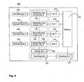
- Fig. 4 schematically illustrates a mobile device 400.
- the mobile device 400 includes a second embodiment of a device for controlling memory accesses for a data stream between selected ports of a plurality of ports coupled to memory.
- Like reference signs indicate components corresponding to those described above with reference to Fig. 1 .
- the second embodiment of the apparatus 120 only differs from first embodiment, as described above with reference to Fig. 1 , in that dedicated streaming flow control units 132 to 138 are arranged in one-to-one association with the ports 112 to 118. Some or all of the streaming flow control units can be arranged at or inside the associated one of the ports 112 to 118.
- the functionality of the controlling unit 130 is thus distributed to a plurality of streaming flow control units 132 to 138.
- Each of the streaming flow control units 132 to 138 is adapted to control the memory accesses that use the associated one of the ports 112 to 118.
- States indicative of the occurrence of a memory access are provided by the streaming flow control unit of the port, via which the memory 110 is accessed.
- the streaming flow control units 132 and 134 associated to the ports 112 and 118 defining one pool of ports for the streaming of the data 350 are mutually linked for exchanging their respective states indicative of the occurrence of a memory access by a linking unit 126.
- Each of the streaming flow control units belonging to the same port of pools thus receives the states from all other streaming flow control units.
- each of the streaming flow control units 132 and 138 autonomously controls further memory accesses via its associated port.
- Fig. 5 schematically illustrates further details of the memory 110 and the apparatus 120 connected to the memory 110. Each of the details can be implemented in the context of the first embodiment shown in Fig. 1 and/or the second embodiment shown in Fig. 4 .
- the apparatus 120 operatively coupled to the memory 110 can be considered as an extended multi-port memory 500 providing data streaming capability.
- the streaming flow control units 132 to 138 are integrated in the associated one of the ports 112 to 118.
- the allocating unit 124 includes a memory access control unit coupled to each of the ports 112 to 118 and to the memory 110.
- the memory includes a data crossbar switch 502 and a plurality of memory units 504. There are N memory units corresponding to the total number N of ports 112 to 118 (i.e., including both ports defining a pool of ports for streaming data and ports not selected for any pool).
- the data crossbar switch 502 connects each of the ports 112 to 118 to a different one of the memory units 504. There is a bijective relation defined by the data crossbar switch 502 between the set of ports 112 to 118 and the set of memory units 504.
- the memory access control unit included in the allocating unit 124 controls the data crossbar switch 502 and thus defines the bijective relation between the ports 112 to 118 and the memory units 504 as a function of time.
- the memory access control unit 124 synchronously sets the data crossbar switch 502 and triggers the memory accesses of the plurality of ports 112 to 118 according to a time slice management (as is indicated by vertical arrows pointing downwards in Fig. 5 ). In each memory access of one of the ports 112 to 118, one data word is either written to or read from the memory 110.
- the memory access control unit 124 controls the data crossbar switch 502 so that consecutive memory accesses via the same port are distributed among the memory units 504 in a round-robin scheme.
- the hardware block 102 writes a burst including a plurality of words via the port 112, so that the first word of the burst is written to the first memory unit of the memory units 504, the second word of the same burst from the hardware block 102 is written to the second memory unit, etc.
- the memory 110 efficiently distributes the available storage capacity of the memory units 504 to the hardware blocks 102 to 108 via the respective ports 112 to 118. All hardware blocks 102 to 108 can access, i.e., read to or write from, the memory 110 simultaneously, because each of the simultaneous memory accesses is directed by means of the data crossbar switch 502 to a physically separate one of the memory units 504. Simultaneously may thus mean that, via each of the ports 112 to 118, one word can be either read or written within the same cycle of the time slice management.
- the multi-port memory 500 allows the hardware blocks 102 to 108 to use the memory 110 either as private memory accessible only to one of the hardware blocks or to selectively define the pool of ports through which data is to be streamed using the portion of the memory 110 allocated to the pool as a streaming buffer.
- the communication between the hardware blocks 102 to 108 and the ports 112 to 118 is structured in data packets.
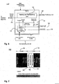
- Fig. 6 shows further details of the port 112 including a passing and transferring unit 142 adapted to process a data packet 700 schematically illustrated in Fig. 7 .
- the processing includes passing a header 702 of the data packet 700 and transferring payload 704 of the data packet 700 to the memory 110.
- the header fields shown with dark shaded background are included in the header 702 in the case of private memory access as well as for streaming data.
- the header field "Address” is a pointer uniquely identified a starting address in the memory 110.
- the header field “Burst Length” corresponds to the number of data words included in the payload 704.
- the header field “Direction” defines whether the payload 704 is to be written to the memory 110 starting at the starting address or is to be read from the memory 110 starting at the starting address.
- the selecting unit 122 is implemented by a streaming control unit including configuration registers.
- the linking unit 126 is implemented by a control crossbar switch.
- the ports defining the pool of ports for streaming data are selected by configuring the configuration registers of the streaming control unit implementing the selecting unit 122.
- the configuration registers include for each of the ports 112 to 118 a streaming mode enabling bit, a streaming buffer size and a pool identifier.
- the configuration registers of ports belonging to the same pool of ports include the same pool identifier.
- the pool identifier also functions as the streaming mode enabling bit, wherein a pool identifier equal to zero indicates that the streaming mode is disabled for the corresponding one of the ports 112 to 108, whereas a pool identifier larger than zero indicates that the streaming mode is enabled.
- the streaming control unit implementing the selecting unit 122 in the first variant of the multi-port memory 500 shown in Fig. 5 globally configures the control streaming path by means of the control crossbar switch implementing the linking unit 126 and enables the streaming mode for each of the ports 112 and 118 in the pool of ports for streaming the data 350.
- the streaming control unit implementing the selecting unit 122 configures the control crossbar switch implementing the linking unit 126 so that the first state 512 provided by the streaming flow control unit 132 of the first port 112 is provided to the at least one streaming flow control unit 138 of all other ports belonging to the same pool of ports.
- the first state 512 is provided to the streaming flow control unit 138 of the port 118 via the control crossbar switch 126.
- the streaming flow control unit 138 provides its second state 518 via the control crossbar switch 126 to the streaming flow control unit 132 of the first port 112.
- Each of the streaming flow control units 132 to 138 includes a streaming buffer fill level monitoring unit 152, as is shown in Fig. 6 for the example of the first port 112.
- a counter for representing the filling level of the allocated memory is included in each of the streaming buffer fill level monitoring units 152.
- the streaming control unit implementing the selecting unit 122 is further adapted to configure the streaming flow control units 132 and 138 of all ports 112 and 118 selected for the pool of ports.
- the streaming flow control units 132 and 138 are enabled, their counters included in the respective streaming buffer fill level monitoring unit 152 is initialized, and the streaming buffer size (i.e., the size of the allocated memory) is provided to the streaming buffer fill level monitoring unit 152 by the selecting unit 122.
- the parsing and transferring unit 142 queues the payload 704 of the burst corresponding to the data packet 700.
- the payload 704 is written starting at the starting address word by word in each time slicing cycle.
- the payload 704 is thus part of the data 350 streamed from the hardware block 102 along the FIFO channel 300 provided by the multi-port memory 110 and controlled by the apparatus 120.
- the first state 512 is provided to the local streaming buffer filling level monitoring unit 152 as well as to the at least one other streaming flow control unit 138 of the at least one further port 118 included in the same pool of ports via the linking unit 126.
- the counter indicating the filing level of the allocated memory in the streaming buffer fill level monitoring unit 152 is updated in response to the first state 512 indicative of a write access so that the counter represents the updated filing level increased by one data word.
- the streaming buffer fill level monitoring unit 152 decreases the filling level represented by its counter by one data word in response to the second state 518 indicating a read access at the at least one other port 118 belonging to the pool of ports.
- the streaming flow control unit 132 includes a counter representing the current filling level of the allocated portion of the memory functioning as the streaming buffer. Based on the streaming buffer size initially provided by the streaming control unit implementing the selecting unit 122 and the current filling level, the streaming flow control unit 132 provides either a transfer halt signal or a transfer resume signal to the parsing and transferring unit 142, which suspends and resumes the memory accesses of the queued payload 704 accordingly.
- streaming flow control unit 132 for the first port 112 has been described with reference to Fig. 6
- corresponding streaming flow control units 134 to 138 are provided for each of the ports 114 to 118.
- the counter of the flow control unit 132 is initialized by the streaming buffer size as the first port 112 is configured for write accesses to the allocated memory.
- a counter equal to the streaming buffer size thus represents an empty streaming buffer in the case of the port 112 configured for write accesses.
- the counter in the streaming buffer fill level monitoring unit 152 is decreased by one.
- the counter is increased by the streaming buffer fill level monitoring unit 152.
- the streaming buffer fill level monitoring unit 152 signals the transfer halt signal to the parsing and transferring unit 142.
- the streaming buffer fill level monitoring unit 152 of the streaming flow control unit 132 signals the transfer resume signal to the parsing and transferring unit 142.
- the streaming flow control unit 138 of the second port 118 includes a streaming buffer fill level monitoring unit including a counter representing the filling level of the commonly allocated portion of the memory 110.
- a streaming buffer fill level monitoring unit including a counter representing the filling level of the commonly allocated portion of the memory 110.
- different streaming flow control units may implement different numerical representation of the filling level.
- the second port 118 configured for read access to the allocated memory can use a different numerical representation compared to the port 112 configured for write access.
- the counter associated to the second port 112 is initialized by zero indicating that the allocated memory including the streaming buffer is empty. In response to the reception of the first state 512 from the streaming flow control unit 132 of the first port 112, the counter is decreased by one.
- the counter In response to the locally provided second state 518 the counter is increased by one.
- the local counter included in the streaming flow control unit 138 of the second port 118 indicates the current filling level of the streaming buffer in terms of data words. Read accesses for reading the payload 704 from the commonly allocated portion of the memory 110 are suspended in response to the transfer halt signal provided by the streaming flow control unit 138 whenever its counter equals zero. Otherwise, one data word is read from the allocated memory in each time slicing cycle.
- the global streaming control unit (which implements the selecting unit 122 in the first variant) is avoided.
- the memory access protocol defining the communication between hardware blocks 102 to 108 and the connected ports 112 to 118 is extended to include header fields providing the information that is included in the configuration registers of the streaming control unit in the first variant.
- the additional header fields are indicated by light shaded backgrounds in Fig. 7 .
- the parsing and transferring unit 142 included in each of the ports 112 to 118 is further configured to process the received data blocks 700 according to the additional header fields.
- the functionality of the selecting unit 122 is thus implemented by the parsing and transferring unit 142.
- the additional header feld "Streaming Mode Enable" 704 includes a bit, which is set to indicate that the data packet 700 relates to streaming data 350.
- the parsing and transferring units 142 enables the streaming flow control unit 132 and queues the payload 704 for write access to the allocated portion of the memory.
- the streaming buffer fill level monitoring unit 152 is provided with the Streaming Buffer Size in the header field 706.
- the parsing and transferring unit 132 further configures the linking unit 126 for mutual exchange of the first and second states 512 and 518 provided by the streaming flow control unit 132 of the port 112 receiving the data packet 700 and the streaming flow control unit 138 of the port 118 indicated in the additional header field "streaming Partner Port No.” 708.
- the streaming flow control units 132 and 138 of those ports selected for the pool of ports for streaming the data 350 control the memory accesses via the ports 112 and 118 of the pool, as described above in the context of the first variant.
- At least some of above embodiments allow reusing a memory accessible via a plurality of ports to achieve the functionality of a FIFO channel that can be selectively established and released between a pair of ports or a larger pool of ports including more than one port configured for read accesses.
- a larger pool can provide the functionality of multi-casting the data input at one port configured for write access and output at a plurality of ports configured for read access.
- the technique can establish a FIFO streaming channel between freely selected ports.
- a latency of the streaming achievable by the present technique may be less than the delay in exchanging the same amount of data entirely written into the shared memory by one hardware block prior to reading the data by another hardware block.
- At least some implementations of the technique are memory efficient. Less memory has to be allocated for the selectable streaming as compared to the memory requirements for exchanging data blocks via shared memory. Additionally, the memory requirements for controlling the memory accesses substantially include, in some embodiments, the counters for autonomously representing the filling level of the streaming buffer and the configuration registers holding the starting address and the streaming buffer size. As a result, the additional memory requirements for controlling the memory accesses are almost neglectable (e.g. compared to the size and complexity of the multi-port memory that has to be provided for private memory accesses of the hardware blocks). Thus, at least some of the embodiments elegantly and cost-effectively extend the multi-port memory to provide a flexible streaming capability.
Landscapes
- Engineering & Computer Science (AREA)
- Theoretical Computer Science (AREA)
- Physics & Mathematics (AREA)
- General Engineering & Computer Science (AREA)
- General Physics & Mathematics (AREA)
- Multimedia (AREA)
- Information Transfer Systems (AREA)
- Data Exchanges In Wide-Area Networks (AREA)
Claims (15)
- Verfahren (200) zum Steuern von Speicherzugriffen für einen Datenstrom zwischen ausgewählten Zugangspunkten einer Vielzahl an Zugangspunkten (112, 114, 116, 118), mit einem Speicher (110) gekoppelt, wobei das Verfahren durch Folgendes gekennzeichnet ist:- Auswählen (210) eines Vorrats von Zugangspunkten umfassend einen ersten Zugangspunkt (112) und einen zweiten Zugangspunkt (118), wodurch Daten (350) zu strömen sind;- Zuweisen (220) eines Abschnitts des Speichers (110) an den Vorrat von Zugangspunkten, wobei der erste Zugangspunkt (112) für einen Schreibzugriff in Bezug auf den zugewiesenen Speicher konfiguriert ist und der zweite Zugangspunkt (118) für einen Lesezugriff in Bezug auf den zugewiesenen Speicher konfiguriert ist; und- Steuern (230), in Abhängigkeit von einem ersten Zustand, anzeigend zumindest das Auftreten eines Schreibzugriffs anhand des ersten Zugangspunkts (112), und einem zweiten Zustand (518), anzeigend zumindest das Auftreten eines Lesezugriffs anhand des zweiten Zugangspunkts (118), zumindest eines aus einem weiteren Schreibzugriff anhand des ersten Zugangspunkts (112) und einem weiteren Lesezugriff anhand des zweiten Zugangspunkts (118).
- Verfahren nach Anspruch 1, wobei die Abhängigkeit durch einen Füllstand des zugewiesenen Speichers dargestellt wird, wobei das Verfahren ferner Folgendes umfasst:- Initialisieren des Füllstands; und- Aktualisieren des Füllstands in Abhängigkeit von dem ersten Zustand (512) und dem zweiten Zustand (518).
- Verfahren nach Anspruch 2, wobei das Steuern zumindest eins von Folgenden umfasst:- Unterbrechen des weiteren Lesezugriffs, wenn der Füllstand anzeigt, dass der zugewiesene Speicher leer ist;- Fortsetzen des weiteren Lesezugriffs, wenn der Füllstand anzeigt, dass der zugewiesene Speicher nicht leer ist;- Unterbrechen des weiteren Schreibzugriffs, wenn der Füllstand anzeigt, dass der zugewiesene Speicher voll ist; und- Fortsetzen des weiteren Schreibzugriffs, wenn der Füllstand anzeigt, dass der zugewiesene Speicher nicht voll ist;
- Verfahren nach Anspruch 2 oder 3, wobei der erste Zustand durch den ersten Zugangspunkt bestimmt wird und der zweite Zustand durch den zweiten Zugangspunkt bestimmt wird, wobei das Verfahren ferner Folgendes umfasst:- Verknüpfen des ersten Zugangspunkts und des zweiten Zugangspunkts zum gegenseitigen Austauschen des ersten Zustands und zweiten Zustands.
- Verfahren nach einem der Ansprüche 2 bis 4, wobei sowohl der erste als auch der zweite Zugangspunkt (112, 118) einen Zähler (152) umfasst, der den Füllstand des zugewiesenen Abschnitts anzeigt.
- Verfahren nach Anspruch 4 und 5, ferner zumindest eins von Folgenden umfassend:- Aktualisieren des Zählers (152) des ersten Zugangspunkts (112) auf Grundlage des ersten Zustands (512) und des ausgetauschten zweiten Zustands (518) von dem zweiten Zugangspunkt (118); und- Aktualisieren des Zählers (152) des zweiten Zugangspunkts (118) auf Grundlage des zweiten Zustands (518) und des ausgetauschten ersten Zustands (512) von dem ersten Zugangspunkt.
- Verfahren nach Anspruch 6, wobei der zweite Zugangspunkt (118) den weiteren Lesezugriff unterbricht, wenn sein Zähler (152) einen niedrigen Füllstand oder einen leeren zugewiesenen Abschnitt anzeigt, und wobei der erste Zugangspunkt (112) den weiteren Schreibzugriff unterbricht, wenn sein Zähler (152) einen hohen Füllstand oder einen vollen zugewiesenen Abschnitt anzeigt.
- Verfahren nach einem der Ansprüche 6 bis 7, wobei der Zähler (152) des zweiten Zugangspunkts (118) mindestens eines der folgenden ist: durch Null initialisiert, in Reaktion auf den ausgetauschten ersten Zustand (512) inkrementiert und in Reaktion auf den bestimmten zweiten Zustand dekrementiert (518), und wobei der Zähler (152) des ersten Zugangspunkts (112) mindestens eines der folgenden ist: durch die Größe des zugewiesenen Abschnitts initialisiert, in Reaktion auf den ausgetauschten zweiten Zustand inkrementiert (518) und in Reaktion auf den bestimmten ersten Zustand dekrementiert (512).
- Verfahren nach einem der Ansprüche 1 bis 8, wobei unterschiedliche Daten zwischen jedem aus einer Vielzahl an Vorräten von Zugangspunkten simultan geströmt werden, wobei jeder der Vorräte entsprechende erste und zweite Zugangspunkte umfasst.
- Verfahren nach einem der Ansprüche 1 bis 9, wobei die Zugangspunkte (112, 114, 116, 118) mit Hardware-Blöcken (102, 104, 106, 108) eines mobilen Übertragungsgeräts (100; 400) verbunden oder verbindbar sind, sodass Daten zwischen einem auswählbaren Vorrat von Hardware-Blöcken geströmt werden, ohne dass eine Verbindung zwischen den Hardware-Blöcken und den Zugangspunkten geändert wird.
- Rechnerprogrammprodukt, umfassend Programmcode-Abschnitte zum Ausführen der Schritte einer der Ansprüche 1 bis 10, wenn das Rechnerprogrammprodukt auf einem oder mehreren Rechnergeräten ausgeführt wird.
- Vorrichtung (120) zum Steuern von Zugriffen für einen Datenstrom zwischen ausgewählten Zugangspunkten einer Vielzahl an Zugangspunkten, mit einem Speicher (110) gekoppelt, wobei die Vorrichtung durch Folgendes gekennzeichnet ist:- eine Auswahleinheit (122; 142), ausgelegt zum Auswählen eines Vorrats von Zugangspunkten einschließlich eines ersten Zugangspunkts (112) und eines zweiten Zugangspunkts (118), wodurch Daten (350) zu strömen sind;- eine Zuweisungseinheit (124), ausgelegt zum Zuweisen eines Abschnitts des Speichers (110) an den Vorrat von Zugangspunkten, wobei der erste Zugangspunkt (112) für einen Schreibzugriff in Bezug auf den zugewiesenen Speicher konfiguriert ist und der zweite Zugangspunkt (118) für einen Lesezugriff in Bezug auf den zugewiesenen Speicher konfiguriert ist; und- Steuerungseinheit (130), ausgelegt zum Steuern, in Abhängigkeit von einem ersten Zustand (512), anzeigend zumindest das Auftreten eines Schreibzugriffs anhand des ersten Zugangspunkts (112), und einem zweiten Zustand (518), anzeigend zumindest das Auftreten eines Lesezugriffs anhand des zweiten Zugangspunkts (118), zumindest eines aus einem weiteren Schreibzugriff anhand des ersten Zugangspunkts (112) und einem weiteren Lesezugriff anhand des zweiten Zugangspunkts (118).
- Vorrichtung nach Anspruch 12, ferner einen Koordinatenschalter (126) umfassend, ausgelegt zum auswählenden Verknüpfen des ersten Zugangspunkts und des zweiten Zugangspunkts zum gegenseitigen Austauschen des ersten Zustands (512) und des zweiten Zustands (518)
- Vorrichtung nach Anspruch 12 oder 13, wobei der Speicher (110) eine Vielzahl an physikalischen Speicherbanken (504) und eine Speicherzugriffssteuerungseinheit (124) umfasst, die ausgelegt ist, um Speicherzugriffe sowohl des Vorrats als auch der Zugangspunkte anzuwenden, die nicht in einem Vorrat in Bezug auf unterschiedliche Speicherbanken (504) in einer verschachtelten Weise ausgewählt werden.
- Vorrichtung nach einem der Ansprüche 12 bis 14, wobei eine fest zugeordnete Strömungsflusssteuerungseinheit (132; 134; 136; 138) für jeden Zugangspunkt aus einer Vielzahl an Zugangspunkten (102, 104, 106, 108) bereitgestellt wird, und wobei die Auswahleinheit (122; 142) ferner ausgelegt ist, um die Strömungsflusssteuerungseinheiten (132, 138) zu aktivieren, die den für den Vorrat ausgewählten Zugangspunkten (112, 118) fest zugeordnet sind.
Applications Claiming Priority (1)
| Application Number | Priority Date | Filing Date | Title |
|---|---|---|---|
| PCT/EP2012/003358 WO2014023316A1 (en) | 2012-08-06 | 2012-08-06 | Technique for controlling memory accesses |
Publications (2)
| Publication Number | Publication Date |
|---|---|
| EP2880542A1 EP2880542A1 (de) | 2015-06-10 |
| EP2880542B1 true EP2880542B1 (de) | 2015-12-09 |
Family
ID=46682791
Family Applications (1)
| Application Number | Title | Priority Date | Filing Date |
|---|---|---|---|
| EP12747975.6A Not-in-force EP2880542B1 (de) | 2012-08-06 | 2012-08-06 | Verfahren zur steuerung von speicherzugriffen |
Country Status (3)
| Country | Link |
|---|---|
| US (1) | US9658952B2 (de) |
| EP (1) | EP2880542B1 (de) |
| WO (1) | WO2014023316A1 (de) |
Families Citing this family (1)
| Publication number | Priority date | Publication date | Assignee | Title |
|---|---|---|---|---|
| US11323305B1 (en) * | 2021-06-22 | 2022-05-03 | Juniper Networks, Inc. | Early detection of telemetry data streaming interruptions |
Family Cites Families (7)
| Publication number | Priority date | Publication date | Assignee | Title |
|---|---|---|---|---|
| EP1368731B1 (de) * | 2000-09-15 | 2010-02-10 | Nxp B.V. | Signalverarbeitungsanlage |
| US6907479B2 (en) * | 2001-07-18 | 2005-06-14 | Integrated Device Technology, Inc. | Integrated circuit FIFO memory devices that are divisible into independent FIFO queues, and systems and methods for controlling same |
| US6795360B2 (en) * | 2001-08-23 | 2004-09-21 | Integrated Device Technology, Inc. | Fifo memory devices that support all four combinations of DDR or SDR write modes with DDR or SDR read modes |
| US20070121499A1 (en) * | 2005-11-28 | 2007-05-31 | Subhasis Pal | Method of and system for physically distributed, logically shared, and data slice-synchronized shared memory switching |
| DE102006041306A1 (de) * | 2006-09-01 | 2008-03-20 | Micronas Gmbh | Speicherverwaltungs-Schaltungsanordnung und Speicherverwaltungsverfahren |
| KR100855587B1 (ko) * | 2007-01-17 | 2008-09-01 | 삼성전자주식회사 | 메일박스 영역을 가지는 멀티 패스 액세스블 반도체 메모리장치 및 그에 따른 메일박스 액세스 제어방법 |
| US8621160B2 (en) * | 2010-12-17 | 2013-12-31 | Futurewei Technologies, Inc. | System and method for contention-free memory access |
-
2012
- 2012-08-06 WO PCT/EP2012/003358 patent/WO2014023316A1/en not_active Ceased
- 2012-08-06 US US14/419,942 patent/US9658952B2/en not_active Expired - Fee Related
- 2012-08-06 EP EP12747975.6A patent/EP2880542B1/de not_active Not-in-force
Also Published As
| Publication number | Publication date |
|---|---|
| US20150178185A1 (en) | 2015-06-25 |
| EP2880542A1 (de) | 2015-06-10 |
| US9658952B2 (en) | 2017-05-23 |
| WO2014023316A1 (en) | 2014-02-13 |
Similar Documents
| Publication | Publication Date | Title |
|---|---|---|
| US6922408B2 (en) | Packet communication buffering with dynamic flow control | |
| US7924708B2 (en) | Method and apparatus for flow control initialization | |
| US9830300B2 (en) | Hybrid programmable many-core device with on-chip interconnect | |
| US20080084893A1 (en) | Network-on-chip apparatus, and method for controlling dynamic frequency for the same | |
| US20110286422A1 (en) | Electronic device and method of communication resource allocation | |
| WO2012120769A1 (ja) | 中継装置、中継装置の制御方法、およびプログラム | |
| JP2011517903A (ja) | パケット交換オンチップ相互接続ネットワークの高速仮想チャネル | |
| EP1744497B1 (de) | Verfahren zum Verwalten einer Vielzahl von virtuellen Verbindungen zur gemeinsamen Nutzung auf einer Verbindungsleitung und Netzwerk zur Implementierung dieses Verfahrens | |
| US10387355B2 (en) | NoC interconnect with linearly-tunable QoS guarantees for real-time isolation | |
| US10423333B2 (en) | System and method for scalable processing of abort commands in a host bus adapter system | |
| US9515963B2 (en) | Universal network interface controller | |
| US10289598B2 (en) | Non-blocking network | |
| CN119807128A (zh) | 通路共享方法、片上网络及电子设备 | |
| CN104081693A (zh) | 光学连接基础设施的重新配置 | |
| EP2880542B1 (de) | Verfahren zur steuerung von speicherzugriffen | |
| CN103827836B (zh) | 存储数据的方法和装置 | |
| Sørensen et al. | A light-weight statically scheduled network-on-chip | |
| US10185606B2 (en) | Scalable autonomic message-transport with synchronization | |
| Chen et al. | Combined packet and TDM circuit switching NoCs with novel connection configuration mechanism | |
| Nguyen et al. | XNoC: A non-intrusive TDM circuit-switched Network-on-Chip | |
| US8346988B2 (en) | Techniques for dynamically sharing a fabric to facilitate off-chip communication for multiple on-chip units | |
| Huang et al. | Providing guaranteed network performance across tenants: Advances, challenges and opportunities | |
| CN110855567A (zh) | 一种环形缓冲自适应片上网络路由器 | |
| CN120880929B (zh) | 通信装置、数据存储方法、芯片、电子设备 | |
| Aust et al. | Real-time processor interconnection network for fpga-based multiprocessor system-on-chip (mpsoc) |
Legal Events
| Date | Code | Title | Description |
|---|---|---|---|
| PUAI | Public reference made under article 153(3) epc to a published international application that has entered the european phase |
Free format text: ORIGINAL CODE: 0009012 |
|
| 17P | Request for examination filed |
Effective date: 20150305 |
|
| AK | Designated contracting states |
Kind code of ref document: A1 Designated state(s): AL AT BE BG CH CY CZ DE DK EE ES FI FR GB GR HR HU IE IS IT LI LT LU LV MC MK MT NL NO PL PT RO RS SE SI SK SM TR |
|
| AX | Request for extension of the european patent |
Extension state: BA ME |
|
| GRAP | Despatch of communication of intention to grant a patent |
Free format text: ORIGINAL CODE: EPIDOSNIGR1 |
|
| GRAS | Grant fee paid |
Free format text: ORIGINAL CODE: EPIDOSNIGR3 |
|
| DAX | Request for extension of the european patent (deleted) | ||
| INTG | Intention to grant announced |
Effective date: 20151005 |
|
| GRAA | (expected) grant |
Free format text: ORIGINAL CODE: 0009210 |
|
| AK | Designated contracting states |
Kind code of ref document: B1 Designated state(s): AL AT BE BG CH CY CZ DE DK EE ES FI FR GB GR HR HU IE IS IT LI LT LU LV MC MK MT NL NO PL PT RO RS SE SI SK SM TR |
|
| REG | Reference to a national code |
Ref country code: GB Ref legal event code: FG4D |
|
| REG | Reference to a national code |
Ref country code: AT Ref legal event code: REF Ref document number: 764856 Country of ref document: AT Kind code of ref document: T Effective date: 20151215 Ref country code: CH Ref legal event code: EP |
|
| REG | Reference to a national code |
Ref country code: IE Ref legal event code: FG4D |
|
| REG | Reference to a national code |
Ref country code: DE Ref legal event code: R096 Ref document number: 602012012923 Country of ref document: DE |
|
| REG | Reference to a national code |
Ref country code: LT Ref legal event code: MG4D |
|
| REG | Reference to a national code |
Ref country code: NL Ref legal event code: MP Effective date: 20151209 |
|
| PG25 | Lapsed in a contracting state [announced via postgrant information from national office to epo] |
Ref country code: ES Free format text: LAPSE BECAUSE OF FAILURE TO SUBMIT A TRANSLATION OF THE DESCRIPTION OR TO PAY THE FEE WITHIN THE PRESCRIBED TIME-LIMIT Effective date: 20151209 Ref country code: NO Free format text: LAPSE BECAUSE OF FAILURE TO SUBMIT A TRANSLATION OF THE DESCRIPTION OR TO PAY THE FEE WITHIN THE PRESCRIBED TIME-LIMIT Effective date: 20160309 Ref country code: LT Free format text: LAPSE BECAUSE OF FAILURE TO SUBMIT A TRANSLATION OF THE DESCRIPTION OR TO PAY THE FEE WITHIN THE PRESCRIBED TIME-LIMIT Effective date: 20151209 |
|
| REG | Reference to a national code |
Ref country code: AT Ref legal event code: MK05 Ref document number: 764856 Country of ref document: AT Kind code of ref document: T Effective date: 20151209 |
|
| PG25 | Lapsed in a contracting state [announced via postgrant information from national office to epo] |
Ref country code: SE Free format text: LAPSE BECAUSE OF FAILURE TO SUBMIT A TRANSLATION OF THE DESCRIPTION OR TO PAY THE FEE WITHIN THE PRESCRIBED TIME-LIMIT Effective date: 20151209 Ref country code: FI Free format text: LAPSE BECAUSE OF FAILURE TO SUBMIT A TRANSLATION OF THE DESCRIPTION OR TO PAY THE FEE WITHIN THE PRESCRIBED TIME-LIMIT Effective date: 20151209 Ref country code: RS Free format text: LAPSE BECAUSE OF FAILURE TO SUBMIT A TRANSLATION OF THE DESCRIPTION OR TO PAY THE FEE WITHIN THE PRESCRIBED TIME-LIMIT Effective date: 20151209 Ref country code: GR Free format text: LAPSE BECAUSE OF FAILURE TO SUBMIT A TRANSLATION OF THE DESCRIPTION OR TO PAY THE FEE WITHIN THE PRESCRIBED TIME-LIMIT Effective date: 20160310 Ref country code: NL Free format text: LAPSE BECAUSE OF FAILURE TO SUBMIT A TRANSLATION OF THE DESCRIPTION OR TO PAY THE FEE WITHIN THE PRESCRIBED TIME-LIMIT Effective date: 20151209 Ref country code: LV Free format text: LAPSE BECAUSE OF FAILURE TO SUBMIT A TRANSLATION OF THE DESCRIPTION OR TO PAY THE FEE WITHIN THE PRESCRIBED TIME-LIMIT Effective date: 20151209 |
|
| PG25 | Lapsed in a contracting state [announced via postgrant information from national office to epo] |
Ref country code: IS Free format text: LAPSE BECAUSE OF FAILURE TO SUBMIT A TRANSLATION OF THE DESCRIPTION OR TO PAY THE FEE WITHIN THE PRESCRIBED TIME-LIMIT Effective date: 20151209 |
|
| PG25 | Lapsed in a contracting state [announced via postgrant information from national office to epo] |
Ref country code: IT Free format text: LAPSE BECAUSE OF FAILURE TO SUBMIT A TRANSLATION OF THE DESCRIPTION OR TO PAY THE FEE WITHIN THE PRESCRIBED TIME-LIMIT Effective date: 20151209 Ref country code: CZ Free format text: LAPSE BECAUSE OF FAILURE TO SUBMIT A TRANSLATION OF THE DESCRIPTION OR TO PAY THE FEE WITHIN THE PRESCRIBED TIME-LIMIT Effective date: 20151209 |
|
| PG25 | Lapsed in a contracting state [announced via postgrant information from national office to epo] |
Ref country code: PT Free format text: LAPSE BECAUSE OF FAILURE TO SUBMIT A TRANSLATION OF THE DESCRIPTION OR TO PAY THE FEE WITHIN THE PRESCRIBED TIME-LIMIT Effective date: 20160411 Ref country code: EE Free format text: LAPSE BECAUSE OF FAILURE TO SUBMIT A TRANSLATION OF THE DESCRIPTION OR TO PAY THE FEE WITHIN THE PRESCRIBED TIME-LIMIT Effective date: 20151209 Ref country code: AT Free format text: LAPSE BECAUSE OF FAILURE TO SUBMIT A TRANSLATION OF THE DESCRIPTION OR TO PAY THE FEE WITHIN THE PRESCRIBED TIME-LIMIT Effective date: 20151209 Ref country code: SM Free format text: LAPSE BECAUSE OF FAILURE TO SUBMIT A TRANSLATION OF THE DESCRIPTION OR TO PAY THE FEE WITHIN THE PRESCRIBED TIME-LIMIT Effective date: 20151209 Ref country code: SK Free format text: LAPSE BECAUSE OF FAILURE TO SUBMIT A TRANSLATION OF THE DESCRIPTION OR TO PAY THE FEE WITHIN THE PRESCRIBED TIME-LIMIT Effective date: 20151209 Ref country code: RO Free format text: LAPSE BECAUSE OF FAILURE TO SUBMIT A TRANSLATION OF THE DESCRIPTION OR TO PAY THE FEE WITHIN THE PRESCRIBED TIME-LIMIT Effective date: 20151209 Ref country code: IS Free format text: LAPSE BECAUSE OF FAILURE TO SUBMIT A TRANSLATION OF THE DESCRIPTION OR TO PAY THE FEE WITHIN THE PRESCRIBED TIME-LIMIT Effective date: 20160409 |
|
| REG | Reference to a national code |
Ref country code: DE Ref legal event code: R097 Ref document number: 602012012923 Country of ref document: DE |
|
| PLBE | No opposition filed within time limit |
Free format text: ORIGINAL CODE: 0009261 |
|
| STAA | Information on the status of an ep patent application or granted ep patent |
Free format text: STATUS: NO OPPOSITION FILED WITHIN TIME LIMIT |
|
| PG25 | Lapsed in a contracting state [announced via postgrant information from national office to epo] |
Ref country code: DK Free format text: LAPSE BECAUSE OF FAILURE TO SUBMIT A TRANSLATION OF THE DESCRIPTION OR TO PAY THE FEE WITHIN THE PRESCRIBED TIME-LIMIT Effective date: 20151209 Ref country code: PL Free format text: LAPSE BECAUSE OF FAILURE TO SUBMIT A TRANSLATION OF THE DESCRIPTION OR TO PAY THE FEE WITHIN THE PRESCRIBED TIME-LIMIT Effective date: 20151209 |
|
| PGFP | Annual fee paid to national office [announced via postgrant information from national office to epo] |
Ref country code: DE Payment date: 20160826 Year of fee payment: 5 |
|
| 26N | No opposition filed |
Effective date: 20160912 |
|
| PG25 | Lapsed in a contracting state [announced via postgrant information from national office to epo] |
Ref country code: SI Free format text: LAPSE BECAUSE OF FAILURE TO SUBMIT A TRANSLATION OF THE DESCRIPTION OR TO PAY THE FEE WITHIN THE PRESCRIBED TIME-LIMIT Effective date: 20151209 |
|
| PG25 | Lapsed in a contracting state [announced via postgrant information from national office to epo] |
Ref country code: BE Free format text: LAPSE BECAUSE OF FAILURE TO SUBMIT A TRANSLATION OF THE DESCRIPTION OR TO PAY THE FEE WITHIN THE PRESCRIBED TIME-LIMIT Effective date: 20151209 |
|
| PG25 | Lapsed in a contracting state [announced via postgrant information from national office to epo] |
Ref country code: MC Free format text: LAPSE BECAUSE OF FAILURE TO SUBMIT A TRANSLATION OF THE DESCRIPTION OR TO PAY THE FEE WITHIN THE PRESCRIBED TIME-LIMIT Effective date: 20151209 |
|
| REG | Reference to a national code |
Ref country code: CH Ref legal event code: PL |
|
| PG25 | Lapsed in a contracting state [announced via postgrant information from national office to epo] |
Ref country code: CH Free format text: LAPSE BECAUSE OF NON-PAYMENT OF DUE FEES Effective date: 20160831 Ref country code: LI Free format text: LAPSE BECAUSE OF NON-PAYMENT OF DUE FEES Effective date: 20160831 |
|
| REG | Reference to a national code |
Ref country code: FR Ref legal event code: ST Effective date: 20170428 |
|
| REG | Reference to a national code |
Ref country code: IE Ref legal event code: MM4A |
|
| PG25 | Lapsed in a contracting state [announced via postgrant information from national office to epo] |
Ref country code: FR Free format text: LAPSE BECAUSE OF NON-PAYMENT OF DUE FEES Effective date: 20160831 Ref country code: IE Free format text: LAPSE BECAUSE OF NON-PAYMENT OF DUE FEES Effective date: 20160806 |
|
| PG25 | Lapsed in a contracting state [announced via postgrant information from national office to epo] |
Ref country code: LU Free format text: LAPSE BECAUSE OF NON-PAYMENT OF DUE FEES Effective date: 20160806 |
|
| REG | Reference to a national code |
Ref country code: DE Ref legal event code: R119 Ref document number: 602012012923 Country of ref document: DE |
|
| PG25 | Lapsed in a contracting state [announced via postgrant information from national office to epo] |
Ref country code: HU Free format text: LAPSE BECAUSE OF FAILURE TO SUBMIT A TRANSLATION OF THE DESCRIPTION OR TO PAY THE FEE WITHIN THE PRESCRIBED TIME-LIMIT; INVALID AB INITIO Effective date: 20120806 |
|
| PG25 | Lapsed in a contracting state [announced via postgrant information from national office to epo] |
Ref country code: MK Free format text: LAPSE BECAUSE OF FAILURE TO SUBMIT A TRANSLATION OF THE DESCRIPTION OR TO PAY THE FEE WITHIN THE PRESCRIBED TIME-LIMIT Effective date: 20151209 Ref country code: HR Free format text: LAPSE BECAUSE OF FAILURE TO SUBMIT A TRANSLATION OF THE DESCRIPTION OR TO PAY THE FEE WITHIN THE PRESCRIBED TIME-LIMIT Effective date: 20151209 Ref country code: CY Free format text: LAPSE BECAUSE OF FAILURE TO SUBMIT A TRANSLATION OF THE DESCRIPTION OR TO PAY THE FEE WITHIN THE PRESCRIBED TIME-LIMIT Effective date: 20151209 Ref country code: MT Free format text: LAPSE BECAUSE OF NON-PAYMENT OF DUE FEES Effective date: 20160831 |
|
| PG25 | Lapsed in a contracting state [announced via postgrant information from national office to epo] |
Ref country code: DE Free format text: LAPSE BECAUSE OF NON-PAYMENT OF DUE FEES Effective date: 20180301 Ref country code: BG Free format text: LAPSE BECAUSE OF FAILURE TO SUBMIT A TRANSLATION OF THE DESCRIPTION OR TO PAY THE FEE WITHIN THE PRESCRIBED TIME-LIMIT Effective date: 20151209 |
|
| PG25 | Lapsed in a contracting state [announced via postgrant information from national office to epo] |
Ref country code: TR Free format text: LAPSE BECAUSE OF FAILURE TO SUBMIT A TRANSLATION OF THE DESCRIPTION OR TO PAY THE FEE WITHIN THE PRESCRIBED TIME-LIMIT Effective date: 20151209 Ref country code: AL Free format text: LAPSE BECAUSE OF FAILURE TO SUBMIT A TRANSLATION OF THE DESCRIPTION OR TO PAY THE FEE WITHIN THE PRESCRIBED TIME-LIMIT Effective date: 20151209 |
|
| PGFP | Annual fee paid to national office [announced via postgrant information from national office to epo] |
Ref country code: GB Payment date: 20180828 Year of fee payment: 7 |
|
| GBPC | Gb: european patent ceased through non-payment of renewal fee |
Effective date: 20190806 |
|
| PG25 | Lapsed in a contracting state [announced via postgrant information from national office to epo] |
Ref country code: GB Free format text: LAPSE BECAUSE OF NON-PAYMENT OF DUE FEES Effective date: 20190806 |