EP2880962B1 - Dispositif de chauffage d'une substance de travail ou d'un adjuvant avec élément de compensation - Google Patents
Dispositif de chauffage d'une substance de travail ou d'un adjuvant avec élément de compensation Download PDFInfo
- Publication number
- EP2880962B1 EP2880962B1 EP13727132.6A EP13727132A EP2880962B1 EP 2880962 B1 EP2880962 B1 EP 2880962B1 EP 13727132 A EP13727132 A EP 13727132A EP 2880962 B1 EP2880962 B1 EP 2880962B1
- Authority
- EP
- European Patent Office
- Prior art keywords
- compensation element
- heating device
- heating
- heat
- conducting body
- Prior art date
- Legal status (The legal status is an assumption and is not a legal conclusion. Google has not performed a legal analysis and makes no representation as to the accuracy of the status listed.)
- Active
Links
Images


Classifications
-
- F—MECHANICAL ENGINEERING; LIGHTING; HEATING; WEAPONS; BLASTING
- F01—MACHINES OR ENGINES IN GENERAL; ENGINE PLANTS IN GENERAL; STEAM ENGINES
- F01N—GAS-FLOW SILENCERS OR EXHAUST APPARATUS FOR MACHINES OR ENGINES IN GENERAL; GAS-FLOW SILENCERS OR EXHAUST APPARATUS FOR INTERNAL-COMBUSTION ENGINES
- F01N3/00—Exhaust or silencing apparatus having means for purifying, rendering innocuous, or otherwise treating exhaust
- F01N3/08—Exhaust or silencing apparatus having means for purifying, rendering innocuous, or otherwise treating exhaust for rendering innocuous
- F01N3/10—Exhaust or silencing apparatus having means for purifying, rendering innocuous, or otherwise treating exhaust for rendering innocuous by thermal or catalytic conversion of noxious components of exhaust
- F01N3/18—Exhaust or silencing apparatus having means for purifying, rendering innocuous, or otherwise treating exhaust for rendering innocuous by thermal or catalytic conversion of noxious components of exhaust characterised by methods of operation; Control
- F01N3/20—Exhaust or silencing apparatus having means for purifying, rendering innocuous, or otherwise treating exhaust for rendering innocuous by thermal or catalytic conversion of noxious components of exhaust characterised by methods of operation; Control specially adapted for catalytic conversion
- F01N3/206—Adding periodically or continuously substances to exhaust gases for promoting purification, e.g. catalytic material in liquid form, NOx reducing agents
- F01N3/2066—Selective catalytic reduction [SCR]
-
- H—ELECTRICITY
- H05—ELECTRIC TECHNIQUES NOT OTHERWISE PROVIDED FOR
- H05B—ELECTRIC HEATING; ELECTRIC LIGHT SOURCES NOT OTHERWISE PROVIDED FOR; CIRCUIT ARRANGEMENTS FOR ELECTRIC LIGHT SOURCES, IN GENERAL
- H05B3/00—Ohmic-resistance heating
- H05B3/02—Details
- H05B3/04—Waterproof or air-tight seals for heaters
-
- H—ELECTRICITY
- H05—ELECTRIC TECHNIQUES NOT OTHERWISE PROVIDED FOR
- H05B—ELECTRIC HEATING; ELECTRIC LIGHT SOURCES NOT OTHERWISE PROVIDED FOR; CIRCUIT ARRANGEMENTS FOR ELECTRIC LIGHT SOURCES, IN GENERAL
- H05B3/00—Ohmic-resistance heating
- H05B3/20—Heating elements having extended surface area substantially in a two-dimensional [2D] plane, e.g. plate-heater
- H05B3/22—Heating elements having extended surface area substantially in a two-dimensional [2D] plane, e.g. plate-heater non-flexible
- H05B3/24—Heating elements having extended surface area substantially in a two-dimensional [2D] plane, e.g. plate-heater non-flexible heating conductor being self-supporting
-
- H—ELECTRICITY
- H05—ELECTRIC TECHNIQUES NOT OTHERWISE PROVIDED FOR
- H05B—ELECTRIC HEATING; ELECTRIC LIGHT SOURCES NOT OTHERWISE PROVIDED FOR; CIRCUIT ARRANGEMENTS FOR ELECTRIC LIGHT SOURCES, IN GENERAL
- H05B3/00—Ohmic-resistance heating
- H05B3/78—Heating arrangements specially adapted for immersion heating
-
- F—MECHANICAL ENGINEERING; LIGHTING; HEATING; WEAPONS; BLASTING
- F01—MACHINES OR ENGINES IN GENERAL; ENGINE PLANTS IN GENERAL; STEAM ENGINES
- F01N—GAS-FLOW SILENCERS OR EXHAUST APPARATUS FOR MACHINES OR ENGINES IN GENERAL; GAS-FLOW SILENCERS OR EXHAUST APPARATUS FOR INTERNAL-COMBUSTION ENGINES
- F01N2610/00—Adding substances to exhaust gases
- F01N2610/02—Adding substances to exhaust gases the substance being ammonia or urea
-
- F—MECHANICAL ENGINEERING; LIGHTING; HEATING; WEAPONS; BLASTING
- F01—MACHINES OR ENGINES IN GENERAL; ENGINE PLANTS IN GENERAL; STEAM ENGINES
- F01N—GAS-FLOW SILENCERS OR EXHAUST APPARATUS FOR MACHINES OR ENGINES IN GENERAL; GAS-FLOW SILENCERS OR EXHAUST APPARATUS FOR INTERNAL-COMBUSTION ENGINES
- F01N2610/00—Adding substances to exhaust gases
- F01N2610/14—Arrangements for the supply of substances, e.g. conduits
- F01N2610/1406—Storage means for substances, e.g. tanks or reservoirs
-
- F—MECHANICAL ENGINEERING; LIGHTING; HEATING; WEAPONS; BLASTING
- F01—MACHINES OR ENGINES IN GENERAL; ENGINE PLANTS IN GENERAL; STEAM ENGINES
- F01N—GAS-FLOW SILENCERS OR EXHAUST APPARATUS FOR MACHINES OR ENGINES IN GENERAL; GAS-FLOW SILENCERS OR EXHAUST APPARATUS FOR INTERNAL-COMBUSTION ENGINES
- F01N2610/00—Adding substances to exhaust gases
- F01N2610/14—Arrangements for the supply of substances, e.g. conduits
- F01N2610/1486—Means to prevent the substance from freezing
-
- H—ELECTRICITY
- H05—ELECTRIC TECHNIQUES NOT OTHERWISE PROVIDED FOR
- H05B—ELECTRIC HEATING; ELECTRIC LIGHT SOURCES NOT OTHERWISE PROVIDED FOR; CIRCUIT ARRANGEMENTS FOR ELECTRIC LIGHT SOURCES, IN GENERAL
- H05B2203/00—Aspects relating to Ohmic resistive heating covered by group H05B3/00
- H05B2203/02—Heaters using heating elements having a positive temperature coefficient
-
- H—ELECTRICITY
- H05—ELECTRIC TECHNIQUES NOT OTHERWISE PROVIDED FOR
- H05B—ELECTRIC HEATING; ELECTRIC LIGHT SOURCES NOT OTHERWISE PROVIDED FOR; CIRCUIT ARRANGEMENTS FOR ELECTRIC LIGHT SOURCES, IN GENERAL
- H05B2203/00—Aspects relating to Ohmic resistive heating covered by group H05B3/00
- H05B2203/021—Heaters specially adapted for heating liquids
-
- Y—GENERAL TAGGING OF NEW TECHNOLOGICAL DEVELOPMENTS; GENERAL TAGGING OF CROSS-SECTIONAL TECHNOLOGIES SPANNING OVER SEVERAL SECTIONS OF THE IPC; TECHNICAL SUBJECTS COVERED BY FORMER USPC CROSS-REFERENCE ART COLLECTIONS [XRACs] AND DIGESTS
- Y02—TECHNOLOGIES OR APPLICATIONS FOR MITIGATION OR ADAPTATION AGAINST CLIMATE CHANGE
- Y02T—CLIMATE CHANGE MITIGATION TECHNOLOGIES RELATED TO TRANSPORTATION
- Y02T10/00—Road transport of goods or passengers
- Y02T10/10—Internal combustion engine [ICE] based vehicles
- Y02T10/12—Improving ICE efficiencies
Definitions
- DE 10 2012 204 106 relates to a heat distribution body for heating a metering system for introducing an operating / auxiliary substance, in particular a reducing agent, in the exhaust gas tract of a self-igniting internal combustion engine.
- the heat distribution body comprises a heat-conducting body and an encapsulation encasing this, which is made of plastic material.
- the nickelleitMap has stress and / or strain-reducing elements.
- a heater comprising at least one PTC element which is electrically contacted via a bus bar.
- auxiliary agent such as urea or a urea-water solution known as AdBlue®
- SCR selective catalytic reduction
- a conversion of the NO x compounds in the exhaust gas of the self-igniting internal combustion engine into water and nitrogen takes place.
- a metering system for introducing the operating / auxiliary substance into the exhaust gas tract of a self-igniting internal combustion engine comprises, inter alia, a heater. This is due to the fact that the operating / auxiliary metered into the exhaust gas by means of the SCR process, ie the reducing agent, freezes below -11 ° C. at low outside temperatures, which is prevented by the provision of the heating.
- the heater has the task, at temperatures below the urea or the HWL freezing point to keep this medium liquid, or possibly already frozen within the system operating / auxiliary material, ie the reductant used thaw again, so that a removal of the operating / Auxiliary substance from a tank is possible again.
- such heaters include a heat spreader body, which is generally made of a good heat conducting material, such as aluminum.
- a heat generator at least one PTC element is used in such Auffilvorraumen.
- made of ceramic material insulating discs, ground side busbars and electrical contact strips are used, which can be equipped with a manufactured from plastic material pre-injection.
- the at least one PTC element, the potential-side busbar and at least one insulating or insulating plate are pressed together in a pocket formed within the heat conducting body or caulked with each other.
- the at least one PTC element, the potential-side busbar and at least one insulating or insulating plate are pressed together in a pocket formed within the heat conducting body or caulked with each other.
- cracking may occur on the insulating element made of ceramic material or on the at least one PTC element, as a result of which a deterioration of the heating power may occur.
- a heater according to the preamble of claim 1 is for example off US2009 / 100824A known.
- At least one compensating element in a heating device for an auxiliary operating substance between the at least one PTC element and a heat distribution body, so that surface defects such as roughness, flatness and parallelism are compensated. Since the at least one compensation element with respect to its surface to the surfaces of the at least one Adjusting the PTC element and the heat spreader during compression, an optimal contact between these components is established. This means that ideally no gaps and / or air bubbles occur, so that the heat transfer between the mentioned components improves considerably and the heating power generated by the at least one PTC element used as a heating element can be significantly increased.
- the significant increase in heating power is due to the fact that with self-regulating heating element with PTC element as a heat source in certain applications, the Abschalteltemperatur with high electrical resistance in the vicinity of the working temperature with minimal resistance. In these applications, a poor heat extraction leads even with a small increase in temperature at the PTC element to a large increase in resistance and thus in turn to a lower heat output.
- the inventively proposed compensation element the heating power control is achieved by better cooling of the PTC element and a resulting lower electrical resistance.
- this is manufactured, for example, as graphite foil or as graphite layer or from another material.
- the at least one compensating element used is electrically conductive and has a good thermal conductivity of> 0.5 W / mK, preferably more than 5 W / mK.
- the electrical conductivity of the at least one compensation element is preferably determined as a function of the maximum occurring current intensity.
- the at least one compensating element has a thickness which is preferably between 0.05 mm to 0.25 mm. Depending on the thickness or the configuration of the at least one inserted PTC element and the heat-conducting body, as well as the contact surfaces, this thickness range can also be undershot or exceeded. This depends on the application and the purpose of use. Depending on the surface, e.g. their roughness, their flatness or the parallelism of the two contact partners is preferable to a minimum thickness of the compensating element, in particular because of improved heat conduction.
- Another feature that has the at least one compensation element is its flexible deformability when pressures occur and / or its compressibility. If the at least one compensating element has these properties, it may adapt to unevenness or tolerances that occur due to production, or fill in and fill gaps left by manufacturing tolerances better, so that optimal contact between the installed components can be achieved.
- the at least one compensating element can be present as a discrete structural body in the form of a plate or a film, but it can also be applied as a coating, for example as a graphite powder coating on the components, or between the components to be joined together to ensure optimum heat transfer by means of a coating ,
- the at least one compensation element is liquid and preferably also gas-tight.
- the at least one compensating element is caulked or pressed in a closed, chambered space in a pocket intended for receiving the PTC element.
- the closed or chambered space is sized slightly larger than the dimensions of the compensating element before caulking or compression.
- At least one compensating element can be represented instead of graphite foil, for example, by a thermal paste, by carbon or even by coating with carbon nanoparticles.
- the proposed solution according to the invention is characterized in that the heat transfer from the at least one PTC element to the heat-conducting body is improved by the at least one compensating element, whereby the PTC element can be cooled particularly well, so that a considerably improved heat dissipation is possible. Because the PTC element does not reach the blocking area so quickly due to increased temperature and electrical resistance. Furthermore, the solution proposed according to the invention makes it possible to shorten the heating-up times of the heating device proposed according to the invention, so that, ideally, a larger churning-up amount can be provided in a shorter heating-up period.
- Another advantageous feature of the proposed solution according to the invention is the fact that a compensation of unevenness or rough surfaces, as in the heat-conducting body of a die-cast material or of a similar material or roughness and unevenness, at the at least one PTC element remain can be achieved.
- at least one flexible compensating element further prevents the breaking or breaking, in particular peripheral regions of the at least one PTC element or a ceramic insulating plate during assembly by pressing. The risk of breakage is ideally eliminated or at least significantly reduced, so that the lifetime of such a configured heating device increases and a reduction in rejects is possible.
- the electrical connection between the at least one inserted PTC element and the heat-conducting body is significantly more robust to ambient gases or aggressive condensates by sealing the electrical contact surfaces due to full-surface contact of the compensation element.
- a significant increase in the life of the heater or the entire metering system for introducing an operating / auxiliary substance in the exhaust gas of an internal combustion engine can be achieved, compared with currently used metering systems.
- a contact resistance eg by contact aging over life, or a variety of heating and cooling cycles
- the tendency to corrosion is significantly reduced by a seal, as there are hardly any gaps left in which the very creepable operating / auxiliary material in the form of urea or a urea-water solution could penetrate.
- the prestressing of the pressing composite within the pocket for receiving the PTC element can be maintained. It can be a compensation of the thermal expansion of the press assembly due to different thermal expansion of the various materials involved or the various contact partners involved reach.
- the inventively proposed at least one compensation element fractures are prevented or at least minimized at the PTC element during assembly and operation. If, however, a PTC element should break at one or more points, then the compensating element impedes movement or migration of the fragments or, if not completely avoided, significantly minimizes them. Due to the resilience of a contact between the compensation element and the individual PTC element fragments is ensured, whereby the electrical and thermal connection or function of the heating is ensured.
- the heater allterieleit analyses and heating element can be completely or partially encapsulated or coated to protect against aggressive ambient media, such as liquids ice or gas, etc., and / or against short circuits.
- This seal geometries mounting options can be considered.
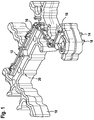
- FIG. 1 is a perspective view of a primatorization still without plastic extrusion refer to.
- a heat-conducting body 10 has an electrical contact strip 12.
- the potential-side electrical contact strip 12 is electrically contacted on the underside of the heat-conducting body 10 by means of a potential-side terminal 14 and a ground-side busbar 18.
- the ground-side busbar 18 is pressed into the top of the heat-conducting body 10;
- the heat-conducting body 10 constitutes a ground-side electrical PTC element 20 contacting.
- at least one PTC element 20 is embedded, which in FIG FIG. 1 enclosed by the material of the heat conducting body 10 and therefore not shown.
- the PTC element 20 may be pressed or clamped or biased with a spring in the space of the bathleit stresses 10.
- the electrical contact strip 12 is as in the perspective view FIG. 1 shown, provided with a Maisologicalnumspritzung 16 at the top of the bathleit stresses 10.
- One lower overmolded area of the contact strip 12 is covered by the heat-conducting body 10 and therefore in FIG. 1 not shown.
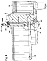
- FIG. 2 shows a perspective view of a heat sink partially shown cut with integrated PTC element, potential-side busbar, at least one insulating element and a compensation element.
- PTC element 20 any other heat-generating elements could be used as heating elements 36.
- the electrical contact strip 12 includes a potential-side busbar 26th
- a heating device in the pocket of the heat conduction body 10 mounted state for example, a flat insulation element 24, which also located in a vertical position potential-side busbar 26, just that at least one PTC element 20 and at least one first compensating element 28 includes.
- the components mentioned are accommodated in the manner of a sandwich structure substantially in a vertical mounting position in the mounting pocket 50 of the heat-conducting body 10 and lie substantially flat against each other.
- the components insulation element 24, potential-side busbar 26, the at least one substantially flat PTC element 20 and the first compensation element 28 are fixed in the mounting pocket 50 by caulking or pressing. In this case, a substantially flat contact of said components with one another. It may already occur in the assembly process first cracks on the insulation element 24 and also the at least one PTC element used as a heating element 20, whereby a slight deterioration of the heating power can be caused. During operation, further crack growth may occur due to the damage caused during installation or due to unevenness.
- At least one compensating element 28 is installed between the PTC element 20 and the heat-conducting body 10.
- the at least one compensation element 28 between any other components 10, 24, 26 and 20 in a mounting pocket 50th Preferably, the installation should be chosen at a location with poor surfaces of the other contacting contact partners. If necessary, several compensation elements 28 can be installed. Without the use of at least one compensating element 28 lead over the lifetime seen in the assembly occurred and resulting from thermal stress cracks together with a decreasing clamping force due to relaxation phenomena to an unacceptable and unacceptable increase in the electrical contact resistance and a deterioration of the thermal coupling , Thus, the heat conduction from the at least one PTC element 20 to the heat-conducting body 10 would worsen.
- the heat conduction 30 without the use of at least one compensating element 28 may also deteriorate significantly by unevenness, since the items are made of stainless steel, ceramic, aluminum alloys, so that shape tolerances occur due to production. Thus, their negative influence on the heating power is compensated or at least significantly reduced by using the at least one compensating element 28 proposed according to the invention.
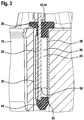
- FIG. 3 shows an arrangement of the at least one PTC element within a mounting pocket in the heat-conducting body before the pressing or the caulking in the mounting pocket.
- the at least one PTC element 20 used as a heating element has on its upper side 44 a contact edge extrusion 16 and a peripheral frame 44 surrounding the contacting region.
- the upper Kunststoff expediumspritzung 16 is connected to the peripheral frame 44 in the contacting region, as formed in this example as a plastic extrusion.
- the at least one heating element serving PTC element 20 is in FIG. 3 shown electrically contacted via the potential-side busbar 26.
- the at least one planar compensating element 28 is shown, as well as an insulation element 24 which is likewise of a planar design.
- the mounting pocket 50 is delimited by the heat-conducting body 10 and the frame 44 circulating around the contacting region.
- Reference numeral 30 denotes a gap-shaped mounting space 30, which is required for insertion into the mounting pocket 50 game for the composite of the at least one first planar compensation element 28, the PTC element 20 of the potential-side busbar 26 and the flat insulation element 24 is required.
- the at least one flat compensating element 28 can also be acted upon by a spring element, not shown here, whereby fractures in the PTC element 20 can be prevented with a corresponding design of the spring force.
- the at least one planar compensating element 28 By means of the at least one planar compensating element 28, uneven or rough surfaces can be compensated both on an electrical contact surface of the at least one PTC element 20 and on the inside of the mounting pocket 50, for example on the second encapsulation part 48. Furthermore, the at least one planar compensation element 28 prevents the breakage of parts of the PTC element 20 during assembly by compression as well as during operation due to thermally induced voltages.
- the electrical connection between the at least one PTC element 20 serving as a heating element and the heat-conducting body 10 is significantly more robust to ambient gases and other aggressive decomposing or corrosion-causing media by sealing the electrical contact surface of the PTC element 20 by the at least one planar compensation element 28. for example condensate.
- the representation according to FIG. 4 is a component combination of the sheet-like insulation element, the busbar and the at least one PTC element and the at least one planar compensation element in the compressed state inside the mounting pocket refer.
- FIG. 4 shows, after pressing or caulking of the component composite of insulation element 24, electrical, potential-side busbar 26, PTC element 20 and at least one flat first compensation element 28, a sandwich structure in the compressed state 34 as shown in FIG FIG. 4 both sides of the production-related unevenness parts of the heat-conducting body 10 of the mounting pocket 50 is present.
- the at least one planar compensation element 28 has a very good thermal conductivity of> 0.5 W / mK, preferably over 5 W / mK.
- the at least one planar compensation element 28 has a thickness of between 0.05 mm and 0.25 mm, depending on the dimensions of the PTC element 20 and the manufacturing quality of the heat-conducting body 10 thicknesses of less than 0.05 mm are very advantageous.
- the thickness of the at least one flat first compensating element 28 may also be smaller or bigger.
- the at least one first compensation element 28 is further characterized by a flexible deformability when pressurized and is deformable so that it adapts to irregularities or this filled.
- the at least one first compensation element 28 can be represented by a graphite foil or a graphite layer.
- the at least one compensating element 28 can also be represented as a coating on one or more of the components 20, 36, 10, 26 and 24.
- first planar compensation element 28 surface defects are compensated for the roughness, flatness and parallelism. This relates both to the roughness or to surface defects on the second contact surface 42 to the heat-conducting body 10 which limits the mounting pocket 50, as well as to the embodiment of a PTC element 20, for example made of ceramic material and therefore fracture-prone, on the first planar compensating element 28 Contact surface 40.
- the chambering of the at least one compensating element 28 is produced by the encapsulated frame 44 extending around the contacting region at the top and bottom sides.
- This Kamm réelle is preferably provided circumferentially, with production and tolerance-related interruptions and no column are allowed, each depending on whether the material used as a compensation element 28 allows this.
- FIG. 5 shows an alternative embodiment of the proposed solution according to the invention, according to which used as a heating element, flanked at least one PTC element on both sides of compensating elements and pressed or caulked within the mounting pocket in the heat conducting body.
- FIG. 5 shows that the substantially in a vertical mounting position 32 in the compressed state 34 embedded in the mounting pocket 50 component composite has a sandwich-like structure.
- the insulating element 24, the potential-side busbar 26, the two flat compensating elements 28 and 38 and flanked by these at least one PTC element 20 are added.
- FIG. 5 shows everyone electrical contact surface 40 and 44 of the PTC element 20 used as a heating element is assigned in each case a planar compensating element 28 and 38, respectively.
- the entire heater is permanently biased, so that adjusts an excellent electrical connection and excellent thermal connection for optimizing the heat transfer serving installation situation.
- the two compensating elements 28 and 38 used here are assigned to the two electrical contact surfaces 40 and 42 of the PTC heating element 20.
- This embodiment also makes it possible to considerably increase the electrical contact area and to seal it particularly well against aggressive media present in the environment.
- the properties of the electrical contact surfaces 40 or 42 of the at least one PTC element 20 used as heating element 36 as well as their electrical contact partners remain permanently within the specifications, so that the service life of the PCT element 20 can be considerably extended.
- ground-side contacting instead of over the heat-conducting body 10, for example, directly via the ground-side busbar 18 done.
- the at least one planar insulating element 24 itself as a compensating element, or to arrange a further compensating element 28 between the insulating element 24 and the floating busbar 26.
- a compensating element 28 can also be arranged between the insulating element 24 and the heat-conducting body 10 of the mounting pocket 50.
- the insulation element 24 is designed as a compensation element, it should be noted that the design is designed to be electrically nonconductive in accordance with the current intensity. Furthermore, even in this embodiment, high demands are to be made on the flatness or low roughness of the adjacent surfaces.
Landscapes
- Chemical & Material Sciences (AREA)
- Engineering & Computer Science (AREA)
- Chemical Kinetics & Catalysis (AREA)
- Health & Medical Sciences (AREA)
- Toxicology (AREA)
- Combustion & Propulsion (AREA)
- Mechanical Engineering (AREA)
- General Engineering & Computer Science (AREA)
- Resistance Heating (AREA)
Claims (9)
- Dispositif de chauffage comportant un corps thermiquement conducteur (10) et un élément chauffant (20, 36) destiné à chauffer ou décongeler un carburant/additif destiné à un moteur à combustion interne, dans lequel le corps thermiquement conducteur (10) comporte une poche de montage (50) qui reçoit l'au moins un élément chauffant (20, 36) avec lequel un contact électrique est établi par l'intermédiaire d'au moins une barre conductrice (18, 26), caractérisé en ce que l'au moins un élément chauffant (20, 36) est en contact par l'intermédiaire d'au moins un élément de compensation plan (28, 38) avec le corps thermiquement conducteur (10) et/ou avec la barre conductrice (18, 26), dans lequel l'au moins un élément de compensation (28, 38) est fixé dans la poche de montage (50) au moyen d'un châssis (44) entourant une zone de contact, d'où il résulte qu'il se produit lors du fonctionnement un effet de force de rappel, et dans lequel les composants, à savoir la barre conductrice, l'élément chauffant et l'élément de compensation, sont fixés dans la poche de montage par calfatage ou compression ou sont sollicités par un élément à ressort de manière à ce qu'il se produise un contact sensiblement plan entre lesdits composants.
- Dispositif de chauffage selon la revendication 1, caractérisé en ce que l'au moins un élément de compensation plan (28, 38) est réalisé sous la forme d'une feuille de graphite souple ou d'un revêtement de graphite.
- Dispositif de chauffage selon la revendication 1, caractérisé en ce que l'au moins un élément de compensation (28, 38) est réalisé sous la forme d'une pâte thermiquement conductrice, d'un revêtement de carbone ou d'un revêtement de nanoparticules.
- Dispositif de chauffage selon l'une quelconque des revendications précédentes, caractérisé en ce que la conductivité thermique de l'au moins un élément e compensation (28, 38) est supérieure à 0,5 W/mK, et plus particulièrement, est supérieure à 5 W/mK.
- Dispositif de chauffage selon l'une quelconque des revendications précédentes, caractérisé en ce que l'épaisseur de l'au moins un élément de compensation plan (28, 38) se situe entre 0,01 mm et 0,5 mm, et plus particulièrement, entre 0,05 mm et 0,25 mm.
- Dispositif de chauffage selon l'une quelconque des revendications précédentes, caractérisé en ce que le matériau de l'au moins un élément de compensation plan (28, 38) est étanche aux liquides et/ou étanche aux gaz.
- Dispositif de chauffage selon l'une quelconque des revendications précédentes, caractérisé en ce qu'un élément de compensation plan (28, 38) est respectivement associé à une première surface de contact électrique (40) et à une seconde surface de contact électrique (42) de l'élément chauffant (20, 36).
- Dispositif de chauffage selon la revendication 7, caractérisé en ce que l'au moins un élément de compensation (28, 38) et/ou un élément d'isolation (24) rend étanche l'au moins une surface de contact électrique (40, 42) vis-à-vis d'un environnement agressif.
- Dispositif de chauffage selon l'une quelconque des revendications précédentes, caractérisé en ce que le dispositif de chauffage est au moins partiellement entouré d'un surmoulage constitué de matière plastique (46, 48).
Applications Claiming Priority (2)
| Application Number | Priority Date | Filing Date | Title |
|---|---|---|---|
| DE102012213417.4A DE102012213417A1 (de) | 2012-07-31 | 2012-07-31 | Aufheizeinrichtung für einen Betriebs-/Hilfsstoff mit Ausgleichselement |
| PCT/EP2013/061388 WO2014019741A1 (fr) | 2012-07-31 | 2013-06-03 | Dispositif de chauffage pour carburant/adjuvant comprenant un élément de compensation |
Publications (2)
| Publication Number | Publication Date |
|---|---|
| EP2880962A1 EP2880962A1 (fr) | 2015-06-10 |
| EP2880962B1 true EP2880962B1 (fr) | 2016-04-27 |
Family
ID=48577010
Family Applications (1)
| Application Number | Title | Priority Date | Filing Date |
|---|---|---|---|
| EP13727132.6A Active EP2880962B1 (fr) | 2012-07-31 | 2013-06-03 | Dispositif de chauffage d'une substance de travail ou d'un adjuvant avec élément de compensation |
Country Status (3)
| Country | Link |
|---|---|
| EP (1) | EP2880962B1 (fr) |
| DE (1) | DE102012213417A1 (fr) |
| WO (1) | WO2014019741A1 (fr) |
Families Citing this family (9)
| Publication number | Priority date | Publication date | Assignee | Title |
|---|---|---|---|---|
| DE102013114471A1 (de) * | 2013-10-31 | 2015-04-30 | Borgwarner Ludwigsburg Gmbh | Heizvorrichtung |
| DE102014210799A1 (de) | 2014-06-05 | 2015-12-17 | Robert Bosch Gmbh | Heizvorrichtung |
| DE102015120250B3 (de) * | 2015-11-23 | 2017-04-13 | Eichenauer Heizelemente Gmbh & Co. Kg | Verfahren zum Herstellen einer Tankheizung und Tankheizung |
| DE102017123546A1 (de) * | 2017-10-10 | 2019-04-11 | Eichenauer Heizelemente Gmbh & Co. Kg | Verfahren zum Herstellen einer Tankheizung sowie Tankheizung |
| DE102017220909A1 (de) * | 2017-11-23 | 2019-05-23 | Robert Bosch Gmbh | Heizvorrichtung, Verfahren zur Herstellung einer Heizvorrichtung |
| DE102018202583A1 (de) * | 2018-02-21 | 2019-08-22 | Robert Bosch Gmbh | Elektrische Heizvorrichtung, insbesondere für ein Abgasnachbehandlungssystem eines Kraftfahrzeugs |
| DE102019204202A1 (de) * | 2019-03-27 | 2020-10-01 | Robert Bosch Gmbh | Vorrichtung zur Beheizung eines Tanks |
| DE102021201507A1 (de) | 2021-02-17 | 2022-08-18 | Robert Bosch Gesellschaft mit beschränkter Haftung | Verfahren und Vorrichtung zur Steuerung einer elektrischen Heizung eines Abgasnachbehandlungssystems |
| DE102023208557A1 (de) * | 2023-09-05 | 2025-03-06 | Robert Bosch Gesellschaft mit beschränkter Haftung | Heizmodul für Fluidfördervorrichtung |
Family Cites Families (7)
| Publication number | Priority date | Publication date | Assignee | Title |
|---|---|---|---|---|
| DE2816076A1 (de) * | 1978-04-13 | 1979-10-25 | Siemens Ag | Heizer mit ferroelektrischem keramik-heizelement |
| DE10335716A1 (de) * | 2003-08-05 | 2005-02-24 | Eichenauer Heizelemente Gmbh & Co. Kg | Verbindung zwischen einem Bauteil und einer dieses umgebenden Umhüllungsschicht, Vorrichtung mit einer solchen Verbindung sowie Verfahren zum Herstellen einer solchen Verbindung |
| US7221860B2 (en) * | 2005-04-22 | 2007-05-22 | Momentive Performance Materials Inc. | Vacuum insulated heater assembly |
| US7836684B2 (en) * | 2005-06-04 | 2010-11-23 | Eichenauer Heizelemente Gmbh & Co. Kg | Urea supply system for a waste gas cleaning catalyst and heating insert suitable therefor |
| EP2161421B2 (fr) * | 2008-09-03 | 2017-08-09 | Delphi International Operations Luxembourg S.à r.l. | Appareil de stockage de réducteur NOx sur un véhicule |
| DE102009012982A1 (de) * | 2009-03-12 | 2010-09-16 | Eichenauer Heizelemente Gmbh & Co. Kg | Heizvorrichtung |
| DE102012204106A1 (de) | 2012-03-15 | 2013-09-19 | Robert Bosch Gmbh | Wärmeverteilkörper für eine Heizung eines SCR-Systems und Heizung |
-
2012
- 2012-07-31 DE DE102012213417.4A patent/DE102012213417A1/de not_active Withdrawn
-
2013
- 2013-06-03 WO PCT/EP2013/061388 patent/WO2014019741A1/fr not_active Ceased
- 2013-06-03 EP EP13727132.6A patent/EP2880962B1/fr active Active
Also Published As
| Publication number | Publication date |
|---|---|
| WO2014019741A1 (fr) | 2014-02-06 |
| EP2880962A1 (fr) | 2015-06-10 |
| DE102012213417A1 (de) | 2014-02-06 |
Similar Documents
| Publication | Publication Date | Title |
|---|---|---|
| EP2880962B1 (fr) | Dispositif de chauffage d'une substance de travail ou d'un adjuvant avec élément de compensation | |
| DE102010020200B4 (de) | Tank zur Bevorratung eines Betriebsstoffs und Kraftfahrzeug | |
| DE102011009428A1 (de) | Thermoelektrisches Modul mit einer Wärmeleitschicht | |
| EP4064788B1 (fr) | Dispositif de chauffage électrique | |
| DE102014212544A1 (de) | Heizung | |
| EP3152421B1 (fr) | Module de chauffage et système de réservoir | |
| DE102011081537A1 (de) | Batteriesystem mit Temperierung mindestens einer Batteriezelle und Kraftfahrzeug | |
| DE102019200817A1 (de) | Kühleinrichtung zur Kühlung von Batteriezellen, Batterie und Kraftfahrzeug | |
| EP1457367B1 (fr) | Appareil de chauffage électrique, en particulier pour véhicule | |
| DE102017209568A1 (de) | Heizvorrichtung | |
| EP2393336B1 (fr) | Caloporteur | |
| DE102022120946A1 (de) | Vorrichtung zum elektrischen Verbinden elektrischer Komponenten, insbesondere eines elektrisch antreibbaren Fahrzeugs, mit einem kühlbaren Kontaktbereich | |
| DE102019211565B4 (de) | Elektrische Heizvorrichtung und Verfahren zu deren Herstellung | |
| DE102013016620A1 (de) | Elektrische Batterie für ein Fahrzeug | |
| DE102019212443B4 (de) | Vorrichtung, Verfahren und Verwendung einer PTC-Heizvorrichtung zur Verkürzung der Anlaufzeit eines Verbrennungsmotors | |
| EP2859598B1 (fr) | Module thermoélectrique et procédé pour le faire fonctionner | |
| DE102025111735B4 (de) | Powermodul mit kühlstruktur und dichtungsmembran zum schutz des powermoduls vor auf korrosion zurückzuführenden ausfall | |
| WO2022171857A1 (fr) | Élément chauffant à coefficient de température positif (ctp), dispositif de chauffage électrique et utilisation d'un élément chauffant ctp | |
| DE102012223087A1 (de) | Vorrichtung zur Entnahme eines gefrierfähigen Fluids aus einem Fluidtank sowie Fluidtank | |
| DE102019200512A1 (de) | Kühlungsanordnung, Batterie, Kraftfahrzeug und Verfahren zum Bereitstellen einer Kühlungsanordnung zur Kühlung eines Batteriemoduls | |
| EP3714138B1 (fr) | Dispositif de chauffage et son procédé de fabrication | |
| DE102011017387A1 (de) | Thermoelektrisches Modul und Verwendung eines thermoelektrischen Moduls | |
| DE102017222301A1 (de) | SCR-Dosiereinheit zur Förderung und Bereitstellung eines flüssigen Abgasreinigungsadditivs | |
| DE102019204202A1 (de) | Vorrichtung zur Beheizung eines Tanks | |
| DE102019206084A1 (de) | Tankheizung, Verfahren zur Herstellung einer Tankheizung |
Legal Events
| Date | Code | Title | Description |
|---|---|---|---|
| PUAI | Public reference made under article 153(3) epc to a published international application that has entered the european phase |
Free format text: ORIGINAL CODE: 0009012 |
|
| 17P | Request for examination filed |
Effective date: 20150302 |
|
| AK | Designated contracting states |
Kind code of ref document: A1 Designated state(s): AL AT BE BG CH CY CZ DE DK EE ES FI FR GB GR HR HU IE IS IT LI LT LU LV MC MK MT NL NO PL PT RO RS SE SI SK SM TR |
|
| AX | Request for extension of the european patent |
Extension state: BA ME |
|
| DAX | Request for extension of the european patent (deleted) | ||
| GRAP | Despatch of communication of intention to grant a patent |
Free format text: ORIGINAL CODE: EPIDOSNIGR1 |
|
| INTG | Intention to grant announced |
Effective date: 20160120 |
|
| GRAS | Grant fee paid |
Free format text: ORIGINAL CODE: EPIDOSNIGR3 |
|
| GRAA | (expected) grant |
Free format text: ORIGINAL CODE: 0009210 |
|
| AK | Designated contracting states |
Kind code of ref document: B1 Designated state(s): AL AT BE BG CH CY CZ DE DK EE ES FI FR GB GR HR HU IE IS IT LI LT LU LV MC MK MT NL NO PL PT RO RS SE SI SK SM TR |
|
| REG | Reference to a national code |
Ref country code: GB Ref legal event code: FG4D Free format text: NOT ENGLISH |
|
| REG | Reference to a national code |
Ref country code: CH Ref legal event code: EP |
|
| REG | Reference to a national code |
Ref country code: AT Ref legal event code: REF Ref document number: 795995 Country of ref document: AT Kind code of ref document: T Effective date: 20160515 |
|
| REG | Reference to a national code |
Ref country code: IE Ref legal event code: FG4D Free format text: LANGUAGE OF EP DOCUMENT: GERMAN |
|
| REG | Reference to a national code |
Ref country code: DE Ref legal event code: R096 Ref document number: 502013002814 Country of ref document: DE |
|
| REG | Reference to a national code |
Ref country code: FR Ref legal event code: PLFP Year of fee payment: 4 |
|
| REG | Reference to a national code |
Ref country code: LT Ref legal event code: MG4D |
|
| REG | Reference to a national code |
Ref country code: NL Ref legal event code: MP Effective date: 20160427 |
|
| PG25 | Lapsed in a contracting state [announced via postgrant information from national office to epo] |
Ref country code: NL Free format text: LAPSE BECAUSE OF FAILURE TO SUBMIT A TRANSLATION OF THE DESCRIPTION OR TO PAY THE FEE WITHIN THE PRESCRIBED TIME-LIMIT Effective date: 20160427 |
|
| PG25 | Lapsed in a contracting state [announced via postgrant information from national office to epo] |
Ref country code: NO Free format text: LAPSE BECAUSE OF FAILURE TO SUBMIT A TRANSLATION OF THE DESCRIPTION OR TO PAY THE FEE WITHIN THE PRESCRIBED TIME-LIMIT Effective date: 20160727 Ref country code: LT Free format text: LAPSE BECAUSE OF FAILURE TO SUBMIT A TRANSLATION OF THE DESCRIPTION OR TO PAY THE FEE WITHIN THE PRESCRIBED TIME-LIMIT Effective date: 20160427 Ref country code: FI Free format text: LAPSE BECAUSE OF FAILURE TO SUBMIT A TRANSLATION OF THE DESCRIPTION OR TO PAY THE FEE WITHIN THE PRESCRIBED TIME-LIMIT Effective date: 20160427 Ref country code: PL Free format text: LAPSE BECAUSE OF FAILURE TO SUBMIT A TRANSLATION OF THE DESCRIPTION OR TO PAY THE FEE WITHIN THE PRESCRIBED TIME-LIMIT Effective date: 20160427 |
|
| PG25 | Lapsed in a contracting state [announced via postgrant information from national office to epo] |
Ref country code: ES Free format text: LAPSE BECAUSE OF FAILURE TO SUBMIT A TRANSLATION OF THE DESCRIPTION OR TO PAY THE FEE WITHIN THE PRESCRIBED TIME-LIMIT Effective date: 20160427 Ref country code: LV Free format text: LAPSE BECAUSE OF FAILURE TO SUBMIT A TRANSLATION OF THE DESCRIPTION OR TO PAY THE FEE WITHIN THE PRESCRIBED TIME-LIMIT Effective date: 20160427 Ref country code: RS Free format text: LAPSE BECAUSE OF FAILURE TO SUBMIT A TRANSLATION OF THE DESCRIPTION OR TO PAY THE FEE WITHIN THE PRESCRIBED TIME-LIMIT Effective date: 20160427 Ref country code: PT Free format text: LAPSE BECAUSE OF FAILURE TO SUBMIT A TRANSLATION OF THE DESCRIPTION OR TO PAY THE FEE WITHIN THE PRESCRIBED TIME-LIMIT Effective date: 20160829 Ref country code: HR Free format text: LAPSE BECAUSE OF FAILURE TO SUBMIT A TRANSLATION OF THE DESCRIPTION OR TO PAY THE FEE WITHIN THE PRESCRIBED TIME-LIMIT Effective date: 20160427 Ref country code: GR Free format text: LAPSE BECAUSE OF FAILURE TO SUBMIT A TRANSLATION OF THE DESCRIPTION OR TO PAY THE FEE WITHIN THE PRESCRIBED TIME-LIMIT Effective date: 20160728 Ref country code: SE Free format text: LAPSE BECAUSE OF FAILURE TO SUBMIT A TRANSLATION OF THE DESCRIPTION OR TO PAY THE FEE WITHIN THE PRESCRIBED TIME-LIMIT Effective date: 20160427 |
|
| PG25 | Lapsed in a contracting state [announced via postgrant information from national office to epo] |
Ref country code: IT Free format text: LAPSE BECAUSE OF FAILURE TO SUBMIT A TRANSLATION OF THE DESCRIPTION OR TO PAY THE FEE WITHIN THE PRESCRIBED TIME-LIMIT Effective date: 20160427 Ref country code: BE Free format text: LAPSE BECAUSE OF NON-PAYMENT OF DUE FEES Effective date: 20160630 |
|
| REG | Reference to a national code |
Ref country code: DE Ref legal event code: R097 Ref document number: 502013002814 Country of ref document: DE |
|
| PG25 | Lapsed in a contracting state [announced via postgrant information from national office to epo] |
Ref country code: CZ Free format text: LAPSE BECAUSE OF FAILURE TO SUBMIT A TRANSLATION OF THE DESCRIPTION OR TO PAY THE FEE WITHIN THE PRESCRIBED TIME-LIMIT Effective date: 20160427 Ref country code: EE Free format text: LAPSE BECAUSE OF FAILURE TO SUBMIT A TRANSLATION OF THE DESCRIPTION OR TO PAY THE FEE WITHIN THE PRESCRIBED TIME-LIMIT Effective date: 20160427 Ref country code: SK Free format text: LAPSE BECAUSE OF FAILURE TO SUBMIT A TRANSLATION OF THE DESCRIPTION OR TO PAY THE FEE WITHIN THE PRESCRIBED TIME-LIMIT Effective date: 20160427 Ref country code: MC Free format text: LAPSE BECAUSE OF FAILURE TO SUBMIT A TRANSLATION OF THE DESCRIPTION OR TO PAY THE FEE WITHIN THE PRESCRIBED TIME-LIMIT Effective date: 20160427 Ref country code: DK Free format text: LAPSE BECAUSE OF FAILURE TO SUBMIT A TRANSLATION OF THE DESCRIPTION OR TO PAY THE FEE WITHIN THE PRESCRIBED TIME-LIMIT Effective date: 20160427 Ref country code: RO Free format text: LAPSE BECAUSE OF FAILURE TO SUBMIT A TRANSLATION OF THE DESCRIPTION OR TO PAY THE FEE WITHIN THE PRESCRIBED TIME-LIMIT Effective date: 20160427 |
|
| REG | Reference to a national code |
Ref country code: CH Ref legal event code: PL |
|
| PG25 | Lapsed in a contracting state [announced via postgrant information from national office to epo] |
Ref country code: SM Free format text: LAPSE BECAUSE OF FAILURE TO SUBMIT A TRANSLATION OF THE DESCRIPTION OR TO PAY THE FEE WITHIN THE PRESCRIBED TIME-LIMIT Effective date: 20160427 |
|
| PLBE | No opposition filed within time limit |
Free format text: ORIGINAL CODE: 0009261 |
|
| STAA | Information on the status of an ep patent application or granted ep patent |
Free format text: STATUS: NO OPPOSITION FILED WITHIN TIME LIMIT |
|
| REG | Reference to a national code |
Ref country code: IE Ref legal event code: MM4A |
|
| 26N | No opposition filed |
Effective date: 20170130 |
|
| PG25 | Lapsed in a contracting state [announced via postgrant information from national office to epo] |
Ref country code: CH Free format text: LAPSE BECAUSE OF NON-PAYMENT OF DUE FEES Effective date: 20160630 Ref country code: LI Free format text: LAPSE BECAUSE OF NON-PAYMENT OF DUE FEES Effective date: 20160630 |
|
| PG25 | Lapsed in a contracting state [announced via postgrant information from national office to epo] |
Ref country code: IE Free format text: LAPSE BECAUSE OF NON-PAYMENT OF DUE FEES Effective date: 20160603 Ref country code: SI Free format text: LAPSE BECAUSE OF FAILURE TO SUBMIT A TRANSLATION OF THE DESCRIPTION OR TO PAY THE FEE WITHIN THE PRESCRIBED TIME-LIMIT Effective date: 20160427 |
|
| REG | Reference to a national code |
Ref country code: FR Ref legal event code: PLFP Year of fee payment: 5 |
|
| GBPC | Gb: european patent ceased through non-payment of renewal fee |
Effective date: 20170603 |
|
| PG25 | Lapsed in a contracting state [announced via postgrant information from national office to epo] |
Ref country code: GB Free format text: LAPSE BECAUSE OF NON-PAYMENT OF DUE FEES Effective date: 20170603 |
|
| PG25 | Lapsed in a contracting state [announced via postgrant information from national office to epo] |
Ref country code: HU Free format text: LAPSE BECAUSE OF FAILURE TO SUBMIT A TRANSLATION OF THE DESCRIPTION OR TO PAY THE FEE WITHIN THE PRESCRIBED TIME-LIMIT; INVALID AB INITIO Effective date: 20130603 |
|
| REG | Reference to a national code |
Ref country code: FR Ref legal event code: PLFP Year of fee payment: 6 |
|
| PG25 | Lapsed in a contracting state [announced via postgrant information from national office to epo] |
Ref country code: IS Free format text: LAPSE BECAUSE OF FAILURE TO SUBMIT A TRANSLATION OF THE DESCRIPTION OR TO PAY THE FEE WITHIN THE PRESCRIBED TIME-LIMIT Effective date: 20160427 Ref country code: LU Free format text: LAPSE BECAUSE OF NON-PAYMENT OF DUE FEES Effective date: 20160603 Ref country code: CY Free format text: LAPSE BECAUSE OF FAILURE TO SUBMIT A TRANSLATION OF THE DESCRIPTION OR TO PAY THE FEE WITHIN THE PRESCRIBED TIME-LIMIT Effective date: 20160427 Ref country code: MK Free format text: LAPSE BECAUSE OF FAILURE TO SUBMIT A TRANSLATION OF THE DESCRIPTION OR TO PAY THE FEE WITHIN THE PRESCRIBED TIME-LIMIT Effective date: 20160427 Ref country code: MT Free format text: LAPSE BECAUSE OF FAILURE TO SUBMIT A TRANSLATION OF THE DESCRIPTION OR TO PAY THE FEE WITHIN THE PRESCRIBED TIME-LIMIT Effective date: 20160427 |
|
| PG25 | Lapsed in a contracting state [announced via postgrant information from national office to epo] |
Ref country code: BG Free format text: LAPSE BECAUSE OF FAILURE TO SUBMIT A TRANSLATION OF THE DESCRIPTION OR TO PAY THE FEE WITHIN THE PRESCRIBED TIME-LIMIT Effective date: 20160427 |
|
| PG25 | Lapsed in a contracting state [announced via postgrant information from national office to epo] |
Ref country code: TR Free format text: LAPSE BECAUSE OF FAILURE TO SUBMIT A TRANSLATION OF THE DESCRIPTION OR TO PAY THE FEE WITHIN THE PRESCRIBED TIME-LIMIT Effective date: 20160427 Ref country code: AL Free format text: LAPSE BECAUSE OF FAILURE TO SUBMIT A TRANSLATION OF THE DESCRIPTION OR TO PAY THE FEE WITHIN THE PRESCRIBED TIME-LIMIT Effective date: 20160427 |
|
| REG | Reference to a national code |
Ref country code: AT Ref legal event code: MM01 Ref document number: 795995 Country of ref document: AT Kind code of ref document: T Effective date: 20180603 |
|
| PG25 | Lapsed in a contracting state [announced via postgrant information from national office to epo] |
Ref country code: AT Free format text: LAPSE BECAUSE OF NON-PAYMENT OF DUE FEES Effective date: 20180603 |
|
| PGFP | Annual fee paid to national office [announced via postgrant information from national office to epo] |
Ref country code: FR Payment date: 20250618 Year of fee payment: 13 |
|
| PGFP | Annual fee paid to national office [announced via postgrant information from national office to epo] |
Ref country code: DE Payment date: 20250814 Year of fee payment: 13 |