EP2881099A2 - Appareil et procédé de déplacement de corps humain - Google Patents
Appareil et procédé de déplacement de corps humain Download PDFInfo
- Publication number
- EP2881099A2 EP2881099A2 EP14195493.3A EP14195493A EP2881099A2 EP 2881099 A2 EP2881099 A2 EP 2881099A2 EP 14195493 A EP14195493 A EP 14195493A EP 2881099 A2 EP2881099 A2 EP 2881099A2
- Authority
- EP
- European Patent Office
- Prior art keywords
- cushion
- guide rail
- lifting mechanism
- human body
- lifting
- Prior art date
- Legal status (The legal status is an assumption and is not a legal conclusion. Google has not performed a legal analysis and makes no representation as to the accuracy of the status listed.)
- Withdrawn
Links
- 238000006073 displacement reaction Methods 0.000 title claims abstract description 42
- 238000000034 method Methods 0.000 title claims description 23
- 230000007246 mechanism Effects 0.000 claims abstract description 120
- 230000033001 locomotion Effects 0.000 claims description 7
- 230000005540 biological transmission Effects 0.000 claims description 3
- 238000010586 diagram Methods 0.000 description 6
- 229910000838 Al alloy Inorganic materials 0.000 description 2
- 230000000694 effects Effects 0.000 description 2
- 239000000463 material Substances 0.000 description 2
- 239000010935 stainless steel Substances 0.000 description 2
- 229910001220 stainless steel Inorganic materials 0.000 description 2
- 238000007792 addition Methods 0.000 description 1
- 238000010276 construction Methods 0.000 description 1
- 238000009434 installation Methods 0.000 description 1
Images


Classifications
-
- A—HUMAN NECESSITIES
- A61—MEDICAL OR VETERINARY SCIENCE; HYGIENE
- A61G—TRANSPORT, PERSONAL CONVEYANCES, OR ACCOMMODATION SPECIALLY ADAPTED FOR PATIENTS OR DISABLED PERSONS; OPERATING TABLES OR CHAIRS; CHAIRS FOR DENTISTRY; FUNERAL DEVICES
- A61G7/00—Beds specially adapted for nursing; Devices for lifting patients or disabled persons
- A61G7/10—Devices for lifting patients or disabled persons, e.g. special adaptations of hoists thereto
- A61G7/1013—Lifting of patients by
- A61G7/1019—Vertical extending columns or mechanisms
-
- A—HUMAN NECESSITIES
- A61—MEDICAL OR VETERINARY SCIENCE; HYGIENE
- A61G—TRANSPORT, PERSONAL CONVEYANCES, OR ACCOMMODATION SPECIALLY ADAPTED FOR PATIENTS OR DISABLED PERSONS; OPERATING TABLES OR CHAIRS; CHAIRS FOR DENTISTRY; FUNERAL DEVICES
- A61G7/00—Beds specially adapted for nursing; Devices for lifting patients or disabled persons
- A61G7/002—Beds specially adapted for nursing; Devices for lifting patients or disabled persons having adjustable mattress frame
- A61G7/012—Beds specially adapted for nursing; Devices for lifting patients or disabled persons having adjustable mattress frame raising or lowering of the whole mattress frame
-
- A—HUMAN NECESSITIES
- A61—MEDICAL OR VETERINARY SCIENCE; HYGIENE
- A61G—TRANSPORT, PERSONAL CONVEYANCES, OR ACCOMMODATION SPECIALLY ADAPTED FOR PATIENTS OR DISABLED PERSONS; OPERATING TABLES OR CHAIRS; CHAIRS FOR DENTISTRY; FUNERAL DEVICES
- A61G7/00—Beds specially adapted for nursing; Devices for lifting patients or disabled persons
- A61G7/10—Devices for lifting patients or disabled persons, e.g. special adaptations of hoists thereto
- A61G7/1001—Devices for lifting patients or disabled persons, e.g. special adaptations of hoists thereto specially adapted for specific applications
-
- A—HUMAN NECESSITIES
- A61—MEDICAL OR VETERINARY SCIENCE; HYGIENE
- A61G—TRANSPORT, PERSONAL CONVEYANCES, OR ACCOMMODATION SPECIALLY ADAPTED FOR PATIENTS OR DISABLED PERSONS; OPERATING TABLES OR CHAIRS; CHAIRS FOR DENTISTRY; FUNERAL DEVICES
- A61G7/00—Beds specially adapted for nursing; Devices for lifting patients or disabled persons
- A61G7/10—Devices for lifting patients or disabled persons, e.g. special adaptations of hoists thereto
- A61G7/1025—Lateral movement of patients, e.g. horizontal transfer
- A61G7/103—Transfer boards
-
- A—HUMAN NECESSITIES
- A61—MEDICAL OR VETERINARY SCIENCE; HYGIENE
- A61G—TRANSPORT, PERSONAL CONVEYANCES, OR ACCOMMODATION SPECIALLY ADAPTED FOR PATIENTS OR DISABLED PERSONS; OPERATING TABLES OR CHAIRS; CHAIRS FOR DENTISTRY; FUNERAL DEVICES
- A61G7/00—Beds specially adapted for nursing; Devices for lifting patients or disabled persons
- A61G7/10—Devices for lifting patients or disabled persons, e.g. special adaptations of hoists thereto
- A61G7/1025—Lateral movement of patients, e.g. horizontal transfer
- A61G7/1034—Rollers, rails or other means
-
- A—HUMAN NECESSITIES
- A61—MEDICAL OR VETERINARY SCIENCE; HYGIENE
- A61G—TRANSPORT, PERSONAL CONVEYANCES, OR ACCOMMODATION SPECIALLY ADAPTED FOR PATIENTS OR DISABLED PERSONS; OPERATING TABLES OR CHAIRS; CHAIRS FOR DENTISTRY; FUNERAL DEVICES
- A61G7/00—Beds specially adapted for nursing; Devices for lifting patients or disabled persons
- A61G7/10—Devices for lifting patients or disabled persons, e.g. special adaptations of hoists thereto
- A61G7/104—Devices carried or supported by
- A61G7/1046—Mobile bases, e.g. having wheels
-
- A—HUMAN NECESSITIES
- A61—MEDICAL OR VETERINARY SCIENCE; HYGIENE
- A61G—TRANSPORT, PERSONAL CONVEYANCES, OR ACCOMMODATION SPECIALLY ADAPTED FOR PATIENTS OR DISABLED PERSONS; OPERATING TABLES OR CHAIRS; CHAIRS FOR DENTISTRY; FUNERAL DEVICES
- A61G7/00—Beds specially adapted for nursing; Devices for lifting patients or disabled persons
- A61G7/10—Devices for lifting patients or disabled persons, e.g. special adaptations of hoists thereto
- A61G7/1049—Attachment, suspending or supporting means for patients
- A61G7/1057—Supported platforms, frames or sheets for patient in lying position
-
- A—HUMAN NECESSITIES
- A61—MEDICAL OR VETERINARY SCIENCE; HYGIENE
- A61G—TRANSPORT, PERSONAL CONVEYANCES, OR ACCOMMODATION SPECIALLY ADAPTED FOR PATIENTS OR DISABLED PERSONS; OPERATING TABLES OR CHAIRS; CHAIRS FOR DENTISTRY; FUNERAL DEVICES
- A61G13/00—Operating tables; Auxiliary appliances therefor
- A61G13/02—Adjustable operating tables; Controls therefor
- A61G13/06—Adjustable operating tables; Controls therefor raising or lowering of the whole table surface
-
- A—HUMAN NECESSITIES
- A61—MEDICAL OR VETERINARY SCIENCE; HYGIENE
- A61G—TRANSPORT, PERSONAL CONVEYANCES, OR ACCOMMODATION SPECIALLY ADAPTED FOR PATIENTS OR DISABLED PERSONS; OPERATING TABLES OR CHAIRS; CHAIRS FOR DENTISTRY; FUNERAL DEVICES
- A61G7/00—Beds specially adapted for nursing; Devices for lifting patients or disabled persons
- A61G7/002—Beds specially adapted for nursing; Devices for lifting patients or disabled persons having adjustable mattress frame
- A61G7/018—Control or drive mechanisms
Definitions
- the present application relates to an apparatus and a method for displacement of a human body, and more specifically, relates to an apparatus and a method for displacing a disabled or mobility-impaired person.
- a disabled or mobility-impaired person especially for a disabled person whose legs or limbs are weak, it is difficult to change his or her position without any assisting means, when he or she wants to move to a wheelchair or get in a car.
- it needs at least two adults to assist with the position changing which is a hard work for his or her families. Therefore, usually the disabled or mobility-impaired person avoids from changing his or her position or travelling. And thus activities of the disabled or mobility-impaired person are restricted. Furthermore, the disabled or mobility-impaired person may be injured when changing his or her position.
- the present application provides an apparatus and a method for displacement of a human body.
- the apparatus has a simple structure, and is reliable and convenient to carry. And the method is convenient for displacing the disabled or mobility-impaired person.
- an apparatus for displacement of a human body comprises a cushion, a height adjustable movable platform, a first lifting mechanism, a guide rail assembly and a roller assembly.
- the first lifting mechanism is arranged on the cushion and is configured for lifting or lowering the cushion.
- One end of the guide rail assembly is positioned on the movable platform, wherein the guide rail assembly includes at least one guide rail.
- the at least one guide rail is simultaneously positioned under the cushion in a horizontal direction or a longitudinal direction at least in part.
- the roller assembly is arranged between the guide rail and the bottom of the cushion, in such a way that the cushion is capable of sliding to or off the movable platform along the guide rail.
- the cushion includes a cushion body and a base plate. Wherein, one end of the first lifting mechanism is fixedly connected to the cushion body and the other end thereof is fixed to the base plate.
- the roller assembly is arranged along a periphery of the bottom of the cushion body. A bottom of the roller assembly is located above the base plate in a vertical direction. A height difference between the bottom of the roller assembly and the base plate is changed by adjusting the lifting mechanism.
- the roller assembly includes a first set of rollers that is located in the horizontal direction at the bottom of the cushion body, and a second set of rollers that is located in the longitudinal direction at the bottom of the cushion body.
- the first set of rollers and the second set of rollers are arranged around the first lifting mechanism, and the first set of rollers and the second set of rollers respectively include at least two pairs of non-steered rollers.
- the apparatus includes two first lifting mechanisms.
- the two first lifting mechanisms are detachably mounted on two sides of the cushion respectively.
- Each of the first lifting mechanisms includes a gear, a rack, a control rod and a lifting plate.
- the gear is mounted on the cushion.
- One end of the control rod is connected to the gear for motion transmission, and the gear is engaged with the rack.
- the lifting plate is arranged on the bottom of the cushion, and is fixedly connected to the rack. The lifting plate is movable in the vertical direction driven by the control rod in such a way that the cushion is lifted or lowered.
- the first lifting mechanism may further include a baffle and a first locking unit.
- one end of the baffle is vertically and detachably mounted on the cushion body.
- the first locking unit includes a stopping rod and a first locking latch.
- the stopping rod is fixed to the other end of the baffle, and the first locking latch is rotatably arranged on the other end of the control rod. The first locking latch is locked on the stopping rod after being rotated a preset angle.
- the first lifting mechanism further includes a gear housing detachably mounted on the cushion, and the gear and the rack are mounted in the gear housing. Projections protruding in a direction away from the axis of the gear housing are formed on two sides of the gear housing. A threaded hole is defined in each of the projections. In this case, the projections are located in the middle of the gear housing in the vertical direction.
- the cushion includes a cushion body and a plurality of stopping blocks.
- the plurality of stopping blocks are distributed and separated in the horizontal direction and the longitudinal direction at the bottom of the cushion body.
- a plurality of guiding slots configured to hold the guide rails inserted are formed between the plurality of stopping blocks.
- the roller assembly includes a plurality of rollers that is separately arranged along the longitudinal direction of the guide rail.
- the guide rail assembly further includes a second locking unit which is arranged at one end of the guide rail.
- the second locking unit includes an engaging portion that is engaged with the movable platform.
- the engaging portion is located at outside of the guide rail, and a locking hole is defined in the engaging portion.
- the second locking unit further includes a rotor which is rotatably inserted in one side of the guide rail.
- a rotary switch is fixed in the front of the rotor, and a second locking latch is sleeved on the rotor.
- a groove for receiving the second locking latch is defined on the surface of the guide rail that is close to the engaging portion. The second locking latch is rotated and then inserted into the locking hole when the rotary switch is rotated.
- the guide rail assembly includes two guide rails, and the two guide rails are connected to each other by a foldable connecting rod.
- the connecting rod includes a first sub-rod and a second sub-rod. Wherein, one end of the first sub-rod is connected to one of the guide rails, and one end of the second sub-rod is connected to the other of the guide rails. The other end of the first sub-rod is movably connected to the other end of the second sub-rod.
- the movable platform includes: a base station configured for carrying the cushion, a base configured for displacing the base station, and a second lifting mechanism.
- the base includes universal wheels arranged at the bottom of the base.
- One end of the second lifting mechanism is height-adjustably connected to the bottom of the base station, and the other end thereof is fixed to the base.
- a plurality of stopping elements are arranged on the base station for preventing the guide rails from sliding off the base station.
- a guide plate is provided between the base station and the second lifting mechanism. Wherein, at least one guide pillar and at least one guide bushing sleeved on the corresponding guide pillar are arranged in the guide plate.
- the first lifting mechanism and the second lifting mechanism comprise a mechanical jack, a hydraulic jack, an electric jack or a cylinder.
- a method for the displacement of a human body which comprises the following steps:
- the cushion includes a cushion body and a base plate, one end of the first lifting mechanism is fixedly connected to the cushion body and the other end thereof is fixed to the base plate.
- the roller assembly includes a first set of rollers that is located in the horizontal direction at the bottom of the cushion body and a second set of rollers that is located in the longitudinal direction at the bottom of the cushion body.
- the step S2 includes: the cushion body is lifted by the first lifting mechanism until a height difference between the bottom of the roller assembly and the base plate is larger than the thickness of the guide rail of the guide rail assembly.
- One end of the guide rail that is positioned in the initial position is extended under the first set of rollers in the horizontal direction of the roller assembly.
- the cushion body is further lowered until the first set of rollers is contacted with the guide rail assembly.
- the base plate is lifted off the initial position, thus the cushion is completely supported on the guide rails via the first set of rollers.
- the cushion in another embodiment, includes a cushion body, and a plurality of guiding slots formed at the bottom of the cushion in the horizontal direction and the longitudinal direction.
- the first lifting mechanism includes a lifting plate arranged at the bottom of the cushion, wherein the lifting plate is movable in the vertical direction.
- the step S2 further includes: the cushion body is lifted by the first lifting mechanism until a height difference between a bottom surface of the cushion body and a top surface of the lifting plate is larger than the thickness of the guide rail. After that, one end of the guide rail that is positioned in the initial position is inserted in the guiding slot arranged in the horizontal direction. The cushion body is lowered by the first lifting mechanism until the cushion body is contacted with the roller assembly, thus the cushion is completely supported on the guide rail via the roller assembly.
- the cushion is capable of being sliding along the guide rail positioned between the initial position and the movable platform, or between the movable platform and the target position.
- the human body is easy to be displaced from the initial position to the target position.
- the displacement process one adult may carry out the displacement easily, since less external force is need (the force is need only during the process of positioning the cushion under the human body and pushing the cushion to slide along the guide rail). Therefore, the displacement of the human body is safe and fast, and the disabled or mobility-impaired person who is displaced may not be injured.
- the configuration of the apparatus is simple, and is convenient for carry.
- Figs. 1-5 illustrate an apparatus for displacement of a human body according to a first embodiment of the present application.
- the apparatus for displacement of a human body is configured for displacing a disabled or mobility-impaired person from an initial position to a target position.
- the apparatus comprises a cushion 1 configured for carrying a human body, a height-adjustable movable platform 2 configured for transferring the cushion 1, and a guide rail assembly 3.
- the guide rail assembly 3 includes at least one guide rail 31.
- Each of the at least one guide rail 31 is simultaneously positioned under the cushion 1 in a horizontal direction or a longitudinal direction at least in part.
- the guide rail assembly 3 includes two guide rails 31.
- each of the guide rails 31 is arranged on the movable platform 2, and the other end thereof is positioned on the initial position or the target position.
- the cushion 1 may be displaced from the initial position to the movable platform 2, or from the movable platform 2 to the target position along the guide rail assembly 3.
- the apparatus further comprises a roller assembly 4 that is cooperated with the guide rail assembly 3 such that the cushion 1 is capable of sliding, and a first lifting mechanism 5 that is configured for lifting or lowering the cushion 1.
- the roller assembly 4 is arranged along the periphery of the bottom of the cushion 1, while the first lifting mechanism 5 is arranged at the center of the bottom of the cushion 1.
- the cushion 1 When the cushion 1 is lifted by the first lifting mechanism 5, the at least one guide rail 31 is inserted in the horizontal direction or the longitudinal direction under the cushion 1. Then the cushion 1 is further lowered by the first lifting mechanism 5. In this way, the cushion 1 is supported on the guide rail 31 via the roller assembly 4 at the bottom of the cushion 1. And then, by a sliding movement of the roller assembly 4 relative to the guide rail 31, the cushion 1 may be displaced from the initial position to the movable platform 2, or from the movable platform 2 to the target position along the guide rail 31.
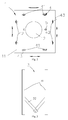
- the cushion 1 includes a cushion body 11, and a base plate 12 in shape of a disc.
- the cushion body 11 is configured for supporting the human body.
- the base plate 12 is configured for supporting the cushion body 11 when no movement occurs.
- the cushion 1 may further include an armrest (not shown) and a detachable backrest 13. Wherein, the detachable backrest 13 supports an upper body when the disabled or mobility-impaired person sits up.
- the roller assembly 4 is arranged along the periphery of the bottom of the cushion 1, and the bottom of the roller assembly 4 is located above the base plate 12 in the vertical direction.
- the roller assembly 4 includes a first set of rollers 41 and a second set of rollers 42.
- the first set of rollers 41 is located at the bottom of the cushion body 11 along the horizontal direction.
- the second set of rollers 42 is located along the longitudinal direction at the bottom of the cushion body 11.
- the first set of rollers 41 and the second set of rollers 42 respectively include at least two pairs of non-steered rollers 43 which are parallel to each other.
- the first set of rollers 41 or the second set of rollers 42 may be chosen to be cooperated with the guide rail assembly 3. That is, the first set of rollers 41 or the second set of rollers 42 may be slid on the guide rail assembly 3. In this way, the rollers 43 of the roller assembly 4 may slide only in one rectilinear direction at a time. And thus, the cushion 1 may be displaced along different directions.
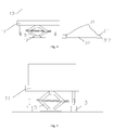
- Figs. 3-4 show the guide rail assembly 3 according to the present application.
- the guide rail assembly 3 includes two guide rails 31 which are parallel to each other.
- the guide rails 31 are configured for supporting the first set of rollers 41 or the second set of rollers 42 thereon. In this way, the cushion 1 is stably supported on the two guide rails 31, and is further capable of sliding along the two guide rails 31.
- a foldable connecting rod 32 is connected between the two guide rails 31.
- the connecting rod 32 includes a first sub-rod (not labeled) and a second sub-rod (not labeled) that are movably connected to each other at one ends. The other ends of the first sub-rod and the second sub-rod are respectively connected to the two guide rails 31.
- the two guide rails 31 may be pulled away from each other with a suitable distance so as to cooperate with the roller assembly 4. Or, the two guide rails 31 may be put together so as to be carried conveniently. It could be understood that, the two guide rails 31 may be separated from each other without the connecting rod 32 connected therebetween.
- each of the guide rails 31 includes a track 312 along which the rollers 43 of the roller assembly 4 may slide.
- the guide rail 31 further includes side plates 311 arranged on both sides of the track 312. In this case, a height of the side plate 311 is larger than that of the track 312. And thus, the rollers 43 may be prevented from sliding off the guide rail 31.
- a length of the guide rail 31 is equal to or larger than a sum of the lengths of the cushion 1 and the movable platform 2.
- the guide rail 31 is capable of bearing a weight of 200KG without deformation.
- the guide rails 31 may be made from aluminium alloy or stainless steel.
- Figs. 4-5 show a configuration of the first lifting mechanism 5.
- one end of the first lifting mechanism 5 is fixedly connected to the cushion body 11, and the other end of the first lifting mechanism 5 is fixed to the base plate 12.
- the first lifting mechanism 5 is configured for adjusting the height difference between the bottom of the roller assembly 4 and the base plate 12.
- a travel of the first lifting mechanism 5 is approximately 50 ⁇ 100mm.
- the height difference between the bottom of the roller assembly 4 and the base plate 12 may be smaller or larger than the thickness of the track 312.
- the first lifting mechanism 5 may be a mechanical jack, a hydraulic jack, an electric jack or a cylinder. More preferably, in this embodiment, the first lifting mechanism 5 is a mechanical jack, since a weight thereof is light and the construction costs low.
- Figs. 4-5 further show the apparatus for displacement of the human body when the first lifting mechanism5 is in different working states.
- the cushion 1 when the human body is in the initial position, the cushion 1 is deposited under the human body, and the base plate 12 is contacted with the initial position. At this time, the first lifting mechanism 5 is in a compressed state, a distance between the cushion body 11 and the base plate 12 is only 10cm. That is, an entire height in the vertical direction of the cushion 1 when it is in the initial position is only 10cm.
- the base plate 12 supports the cushion body 11 and the human body, and the bottom of the roller assembly is located above the base plate 12 in the vertical direction. That is, the roller assembly is suspended.
- the guide rails can not be inserted under the cushion body 11.
- the cushion body 11 and the roller assembly 4 together are lifted. And thus, the guide rail assembly 3 may be positioned under the roller assembly 4, if the height difference between the bottom of the roller assembly 4 and the base plate 12 is larger than the thickness of the track 312.
- the cushion body 11 is further lowered until the roller assembly 4 is contacted with the guide rail assembly 3, and the base plate 12 is lifted off the initial position, the cushion 1 may be completely supported on the guide rails 31 of the guide rail assembly 3 via the roller assembly 4. In this way, the cushion 1 may be displaced from the initial position to the movable platform 2 along the guide rails 31, or displaced from the movable platform 2 to the target position.
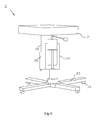
- Figs. 1 and 6 show two different embodiments of the movable platform 2 according to the present application respectively.
- the movable platform 2 includes a base station 21 for carrying the cushion 1, a second lifting mechanism 22 for adjusting a height of the base station 21, and a base 23 for displacing the base station 21.
- a plurality of stopping elements are arranged around the periphery of the base station 21. And thus, the guide rails 31 are prevented from sliding off the base station 21.
- the second lifting mechanism 22 is height-adjustably connected to the center of the bottom of the base station 21, and the other end of the second lifting mechanism 22 is fixed to the base 23.
- the second lifting mechanism 22 may be a mechanical jack, a hydraulic jack, an electric jack or a cylinder.
- the second lifting mechanism 22 is a mechanical jack.
- the second lifting mechanism 22 is a hydraulic jack.
- the second lifting mechanism 22 may be a combination of two mechanical or hydraulic jacks stacked on one another (not shown). In this way, a desire travel (for example, 470mm) may be achieved, when the height difference between the initial position or the target position and the movable platform 2 is large.
- a universal wheel 24 is arranged at the bottom of each of the brackets.
- the movable platform 2 may be rotated in any directions.
- a locking member (not shown) may be further provided on the universal wheel 24. And thus, the universal wheel may be locked and the movable platform 2 is in turn fixed.
- At least one guide pillar 25 may be provided at the bottom of the base station 21.
- at least one guide bushing 26 corresponding to the at least one guide pillar 25 may be further provided.
- the at least one guide bushing 26 is connected to the other end of the second lifting mechanism 22.
- one guide pillar 25 is provided in the cases as shown in Figs. 1 and 6 .
- six guide pillars 25 distributed around the second lifting mechanism 22 may be provided in other cases. In this case, the guide pillars 25 are cooperated with the corresponding guide bushings 26 so as to support the base station 21.
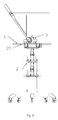
- a working process of the apparatus according to the present embodiment may be briefly described below (e.g. the human body is displaced from the wheelchair to the car seat):
- the guide rails 31 should be inserted in a different direction.
- Figs. 7-13 illustrate an apparatus for displacement of a human body according to a second embodiment of the present application.
- the apparatus comprises a cushion 1, a height adjustable movable platform 2, a guide rail assembly 3, a roller assembly 4 and a first lifting mechanism 5.
- the guide rail assembly 3 includes at least one guide rail 31.
- Each of the at least one guide rail 31 is simultaneously positioned under the cushion 1 in the horizontal direction or the longitudinal direction at least in part.
- One end of the guide rails 31 is engaged with the movable platform 2, and the other end thereof is positioned on the initial position or the target position.
- the roller assembly 4 is arranged in the guide rails 31 in the longitudinal direction of the guide rails 31.
- the two first lifting mechanisms 5 are detachably mounted on two sides of the cushion 1 respectively, and are configured for lifting or lowering the cushion 1.
- the cushion 1 When the cushion 1 is lifted by the first lifting mechanism 5, at least one guide rail 31 is inserted in the horizontal direction or the longitudinal direction under the cushion 1. Then the cushion 1 is further lowered by the first lifting mechanism 5. In this way, the cushion 1 is supported on roller assembly 4 in the guide rail 31. After that, the cushion 1 is displaced from the initial position to the movable platform 2 along the guide rail 31, or displaced from the movable platform 2 to the target position via the roller assembly 4.
- the configuration of the movable platform 2 is similar to that as shown in Figs. 1 and 6 , which includes a base station 21, a second lifting mechanism 22, and a base 23.
- a plurality of universal wheels 24 are arranged at the bottom of the base.
- a plurality of stopping elements 211 are arranged around the periphery of the base station 21. In this way, the guide rails 31 are prevented from sliding off the base station 21.
- the second lifting mechanism 22 may be a mechanical jack, a hydraulic jack, an electric jack or a cylinder. Specifically, as shown in Fig. 7 , the second lifting mechanism 22 is a mechanical jack. And more preferably, the second lifting mechanism 22 may be a combination of two mechanical jacks stacked on one another.
- At least one guide pillar 25 and at least one guide bushing 26 sleeved on the corresponding at least one guide pillar 25 may be provided at the bottom of the base station 21.
- at least one guide plate 27 is provided between the base station 21 and the second lifting mechanism 22. The at least one guide pillar 25 is passed through the guide plate 27.
- four guide pillars are cooperated with the corresponding guide bushings 26 so as to support the base station 21.
- Fig. 9 shows the cushion 1 and the first lifting mechanism 5 according to the present embodiment.
- the cushion 1 includes a cushion body 11 configured for supporting the human body, and a plurality of stopping blocks 14 configured for guiding the guide rails 31.
- a plurality of guiding slots 15 configured to hold the guide rails 31 inserted are formed between the plurality of stopping blocks 14.
- the plurality of stopping blocks 14 are distributed and separated in the horizontal direction and the longitudinal direction at the bottom of the cushion body 11.
- the guiding slots 15 are formed in the horizontal direction and the longitudinal direction.
- the human body may be displaced in different directions.
- two guiding slots 15 are formed in both of the horizontal direction and the longitudinal direction.
- the two guiding slots 15 are symmetrically arranged about a central line of the cushion body 11 so as to improve stability of the cushion 1 during the displacement. It could be understood that, it is possible that only one guiding slot 15 is positioned in both of the horizontal direction and the longitudinal direction. In this case, the guiding slot 15 is arranged at the centre of the cushion body 11.
- each of the first lifting mechanisms 5 includes a gear 53 mounted on the cushion 1, a rack 54, a lifting plate 55, and a control rod 56.
- One end of the control rod 56 is connected to the gear 53 for motion transmission, and the gear 53 is engaged with the rack 54.
- the lifting plate 55 is arranged on the bottom surface of the cushion 1, and is fixed to the rack 54. Therefore, when the control rod 56 is rotated, the gear is rotated along with the control rod, and the rack 54 carries out a linear motion in the vertical direction. In this way, the lifting plate 55 carries out a linear motion in the vertical direction. And thus, the lifting plate 55 may be protruded downward from the cushion body 11 or returned upward to contact with the cushion body 11.
- the cushion 1 can be lifted up or lowered down.
- the lifting plate 55 When the lifting plate 55 is protruded downward from the cushion body 11, the cushion 1 is lifted up via the lifting plate 55.
- the guide rail 31 may be inserted under the cushion body 11.
- the lifting plate When the lifting plate is returned upward to contact with the cushion body 11, the whole cushion 1 may be supported on the movable platform 2 or the target position, facilitating the cushion 1 being pulled out.
- the first lifting mechanism may further include a baffle 51 used as a backrest, and a first locking unit 57 configured for locking the control rod 56.
- a baffle 51 used as a backrest
- a first locking unit 57 configured for locking the control rod 56.
- one end of the baffle 51 is vertically and detachably mounted on the cushion body 11 with bolts or the like.
- the first locking unit 57 includes a stopping rod 571 and a first locking latch 572.
- the stopping rod 571 is fixed to the other end (opposite to the end that is mounted on the cushion) of the baffle 51.
- the first locking latch 572 is rotatably arranged on the other end (opposite to the end that is connected to the gear) of the control rod 56. After the control rod 56 has been rotated to reach a desire position, the first locking latch 572 is rotated a preset angle. Thereby, the first locking latch 572 is locked on the stopping rod 571, and thus the control rod 56 is locked in the desire position. When the first locking latch 572 is counter rotated the same angle, the control rod 56 can be unlocked.
- the preset angle is 90°.
- the first lifting mechanism 5 further includes a gear housing 52 configured for holding the gear 53 and the rack 54.
- the gear housing 52 is fixed on the baffle 51 with bolts or the like. And thus, the gear housing 52 is detachably connected to the cushion body 11.
- the gear 53 and the rack 54 are mounted in the gear housing 52.
- projections 521 are formed on two sides of the gear housing 52. Wherein, the projections 521 are protruded in the direction away from the axis of the gear housing 52.
- a threaded hole (not shown) is defined in each of the projections 521.
- a fixing screw 522 runs through the threaded hole, and is finally fixed onto the cushion body 11.
- the gear housing 52 may be fixed onto the cushion body 11.
- the projections 521 are arranged at a distance from the top surface of the cushion body 11 in the vertical direction.
- the projections 521 are located in the middle of the gear housing in the vertical direction. In this way, it is not easy for the projections 521 to be deformed when the gear housing is fixed to the cushion body. And thus the installation accuracy of the threaded hole and the fixing screw can be ensured.
- Figs. 10-11 show a first lifting mechanism 5 according to another embodiment of the present application. It can be seen that, the configuration of the first lifting mechanism 5 in this embodiment is similar to that in the embodiment as shown in Fig. 9 . Differences between these two include: the position of the projections 521, and the configuration of the first locking unit 57.
- the projections 521 are located at the lower end of the gear housing 52, and are contacted with the cushion body 11.
- the fixing screw 522 runs through the threaded hole and is finally fixed onto the cushion body 11, the bottom surface of the projections 521 are abutted against the cushion body 11. In this way, locking force between the gear housing 52 and the cushion body 11 can be enhanced.
- the configuration of the first locking unit 57 may be seen from Figs. 10-11 .
- the first locking unit 57 includes a stopping rod 571 and a locking strut 573. Both ends of the locking strut 573 are provided with flanges, and the locking strut 573 is retractably inserted in the other end of the control rod 56. After the control rod 56 is rotated to reach a desire position, the locking strut 573 may be moved toward the centre of the cushion 1. In this way, the flange of the locking strut 573 may be locked on the stopping rod 571, and thus the control rod 56 may be locked in the desire position.
- the locking strut 573 When the locking strut 573 is moved away from the centre of the cushion 1, the locking strut 573 is released from the stopping rod 571. And thus the control rod 56 may be unlocked.
- threads (not shown) may be defined at both ends of the locking strut, and nuts (not shown) fitting with the threads may also be provided. Therefore, the flanges of the locking strut 573 may be locked on the stopping rod 571 by adjusting the position of the nuts.
- Lifting process when the control rod 56 is rotated manually, the gear 53 is rotated, and the rack 54 and the lifting plate 55 are moved downward in the vertical direction. In this way, the lifting plate 55 is protruded from the cushion body 11, and thus the cushion 1 is lifted.
- the control rod 56 may be locked by the first locking unit 57.
- the height difference between the bottom surface of cushion body 1 and the top surface of the lifting plate 55 may be controlled to be larger than the height of the guide rail 31, so that the guide rails 31 may be inserted under the cushion body 11.
- the lifting mechanism 5 may be a mechanical jack, a hydraulic jack, an electric jack or a cylinder.
- Fig. 12 shows a guide rail assembly 3 and a roller assembly 4 according to an embodiment of the present application.
- the roller assembly 4 includes a plurality of non-steered rollers 43 that is separately arranged in the guide rail 31 along the longitudinal direction thereof.
- the cushion 1 may be supported by the rollers 43 and may be slid along the guide rail 31 with the help of the rollers 43.
- the length of the guide rail 31 is equal to or larger than a sum of the lengths of the cushion and the movable platform 2.
- the guide rail 31 is capable of bearing a weight of 200KG without deformation.
- the guide rail 31 may be made from aluminium alloy or stainless steel.
- the guide rail assembly 3 further includes a second locking unit 33.
- the second locking unit 33 is arranged at one end of the guide rail 31, and includes an engaging portion 331 that is engaged with the movable platform 2.
- the engaging portion 331 is of an "L" shape, and is located at outside of the guide rail 31.
- a locking hole (not labeled) is further defined in the engaging portion 331.
- the second locking unit 33 further includes a rotor 333 which is rotatably inserted in one side of the guide rail 31.
- a rotary switch 332 is fixed in the front of the rotor 333, and a second locking latch 334 is sleeved on the rotor 333.
- a groove (not labeled) for receiving the second locking latch 334 is defined on the surface of the guide rail 31 that is close to the engaging portion 331.
- the rotary switch 332 is rotated, and then the second locking latch 334 is rotated in the groove and extends to the outside of the guide rail. In this way, the second locking latch 334 is in turn inserted in the locking hole of the engaging portion 331. While the guide rail 31 needs to be disassembled from the movable platform 2, the rotary switch 332 is counter rotated. Therefore, the second locking latch 334 is withdrawn from the locking hole and is returned back into the guide rail 31.
- the guide rail assembly 3 may include two guide rails 31 parallel to each other, so that the cushion 1 may be stably supported on the guide rail assembly 3.
- the two guide rails 31 are connected to each other with a foldable connecting rod (not shown). In this way, the distance between the two guide rails 31 may be adjusted as required.
- the two guide rails 31 may be put together with the connecting rod when being not in use. In this way, the guide rails 31 may be carried conveniently. It could be understood that, the two guide rails may be separated from each other without a connecting rod 32 connected therebetween.
- the apparatus according to the present application further includes a mounting base 6.
- the mounting base includes an even mounting plate 61 and a height increasing pad 62 fixedly connected to the mounting plate 61.
- the mounting plate 61 is made from rigid material, while the height increasing pad 62 is preferably made from plastic material.
- the guide rail 31 should be inserted in a different direction.
- the apparatus may be folded together, and thus the apparatus is convenient for carry.
- the present application further provides a method for displacement of a human body, which is used for displacing a disabled or mobility-impaired person from an initial position to a target position.
- the method comprises the following steps:
- step S1 when the human body is in the initial position, the cushion 1 is positioned under the human body.
- the movable platform 2 is displaced to a position close to the initial position, and the height of the movable platform 2 is adjusted, so that the surface of the movable platform 2 is substantially at the same level as the initial position.
- step S2 the moving direction of the human body is determined according to the initial position and the orientation of the human body.
- the height of the cushion 1 is adjusted by the first lifting mechanism 5.
- one end of the guide rails 31 may be arranged under the cushion 1 in the horizontal direction or the longitudinal direction, and the other end of the guide rails 31 is positioned in the initial position.
- the height of the cushion 1 is further adjusted by the first lifting mechanism 5 so that the cushion 1 is completely supported on the guide rail assembly 3 via the roller assembly 4.
- step S3 the cushion 1 is displaced from the initial position to the movable platform 2.
- the guide rails 31 are then pulled out after the cushion 1 is lifted again.
- step S4 the movable platform 2 is displaced to the position close to the target position.
- the height of the movable platform is further adjusted, so that the surface of the movable platform 2 is substantially at the same level as the target position.
- step S5 the moving direction of the human body is determined according to the initial position and the orientation of the human body.
- the height of the cushion 1 is adjusted by the first lifting mechanism 5.
- one end of the guide rails 31 may be arranged under the cushion 1 in the horizontal direction or the longitudinal direction, and the other end of the guide rails 31 is positioned in the target position.
- the height of the cushion 1 is further adjusted, and thus the cushion 1 is completely supported on the guide rail assembly 3 via the roller assembly 4.
- step S6 the cushion 1 is displaced from the movable platform 2 to the target position.
- the guide rails 31 are then pulled out after the cushion 1 is lifted up again.
- the cushion 1 is lowered so as to be pulled out.
- the orientations and moving directions of the human body should be adjusted as required.
- the guide rails 31 may be cooperated with the first set of rollers 41 in the horizontal direction or the second set of the rollers 42 in the longitudinal direction. Thereby, the moving direction of the human body may be adjusted.
- the guide rails 31 may be inserted in the guiding slots positioned in the horizontal direction or the longitudinal direction so as to adjust the moving direction of the human body.
- step S2 may be achieved by two different manners a and b described below, since the positions of the roller assembly 4 are different.
- the guide rails 31 should be arranged in the longitudinal direction under the cushion 1.
- the cushion is capable of being sliding along the guide rails positioned between the initial position and the movable platform, or between the movable platform and the target position.
- the human body is easy to be displaced from the initial position to the target position.
- one adult may carry out the displacement easily, since less external force is need (the force is need only during the process of positioning the cushion under the human body and pushing the cushion to slide along the guide rail). Therefore, the displacement of the human body is safe and fast, and the disabled or mobility-impaired person who is displaced may not be injured.
- the configuration of the apparatus is simple, and is convenient for carry.
Landscapes
- Health & Medical Sciences (AREA)
- Nursing (AREA)
- Life Sciences & Earth Sciences (AREA)
- Animal Behavior & Ethology (AREA)
- General Health & Medical Sciences (AREA)
- Public Health (AREA)
- Veterinary Medicine (AREA)
- Invalid Beds And Related Equipment (AREA)
- Auxiliary Methods And Devices For Loading And Unloading (AREA)
- A Measuring Device Byusing Mechanical Method (AREA)
Applications Claiming Priority (1)
| Application Number | Priority Date | Filing Date | Title |
|---|---|---|---|
| CN201310645888.XA CN103735378B (zh) | 2013-12-04 | 2013-12-04 | 一种人体移位辅助装置和人体移位方法 |
Publications (2)
| Publication Number | Publication Date |
|---|---|
| EP2881099A2 true EP2881099A2 (fr) | 2015-06-10 |
| EP2881099A3 EP2881099A3 (fr) | 2015-10-21 |
Family
ID=50492501
Family Applications (1)
| Application Number | Title | Priority Date | Filing Date |
|---|---|---|---|
| EP14195493.3A Withdrawn EP2881099A3 (fr) | 2013-12-04 | 2014-11-28 | Appareil et procédé de déplacement de corps humain |
Country Status (3)
| Country | Link |
|---|---|
| US (1) | US20150150741A1 (fr) |
| EP (1) | EP2881099A3 (fr) |
| CN (1) | CN103735378B (fr) |
Cited By (1)
| Publication number | Priority date | Publication date | Assignee | Title |
|---|---|---|---|---|
| CN111685952A (zh) * | 2020-06-12 | 2020-09-22 | 河海大学常州校区 | 一种助老上下床装置 |
Families Citing this family (19)
| Publication number | Priority date | Publication date | Assignee | Title |
|---|---|---|---|---|
| US9233041B2 (en) * | 2012-06-01 | 2016-01-12 | Ngozi A Iheoma | Compact and portable gynecological exam device |
| CN105012088A (zh) * | 2015-07-20 | 2015-11-04 | 甄华伟 | 简易式易操控移位机 |
| CN105105560A (zh) * | 2015-09-28 | 2015-12-02 | 成都愚创科技有限公司 | 一种适用于残疾人的升降式床位 |
| US10441483B2 (en) * | 2016-07-20 | 2019-10-15 | Stryker Corporation | Emergency patient motion system |
| CN106943246B (zh) * | 2017-04-25 | 2018-06-05 | 温州大学 | 一种术后病人转移担架车 |
| CN107174416B (zh) * | 2017-06-06 | 2019-04-02 | 杨军立 | 一种救护车用载重转运平台 |
| CN108403377B (zh) * | 2018-03-07 | 2024-07-09 | 四川合顺微创科技有限公司 | 可调节式侧卧体位固定系统及方法 |
| CN108938238A (zh) * | 2018-05-15 | 2018-12-07 | 杜赣 | 一种医疗用术后病人转移病床 |
| CN108852649A (zh) * | 2018-07-26 | 2018-11-23 | 刘宗群 | 一种用于医疗担架车上的智能电动滑行的担架装置 |
| CN109015595B (zh) * | 2018-08-01 | 2021-01-26 | 湖南华菱涟源钢铁有限公司 | 一种机器人滑动底座 |
| CN109009798B (zh) * | 2018-08-20 | 2019-11-19 | 燕山大学 | 多功能卧床病人转运装置 |
| CN109589212A (zh) * | 2018-11-30 | 2019-04-09 | 无锡市太湖医院 | 多功能医用平车 |
| CN111053649A (zh) * | 2020-01-01 | 2020-04-24 | 瓮海英 | 一种运送转载人体的轮椅担架车 |
| CN111329698A (zh) * | 2020-03-21 | 2020-06-26 | 张晓卫 | 一种医用心内科保健台 |
| CN111588564B (zh) * | 2020-04-24 | 2021-05-28 | 南通大学附属医院 | 一种胸外科组合护理装置 |
| CN111938961A (zh) * | 2020-08-21 | 2020-11-17 | 邢力丹 | 一种护理用移动式盥洗装置 |
| CN114288119A (zh) * | 2021-12-12 | 2022-04-08 | 赛金(天津)智能养老产业发展有限公司 | 一种具有多姿态床面移位组合移动功能的移位机 |
| CN114432049B (zh) * | 2022-02-07 | 2022-12-16 | 迈兰达(江苏)医疗设备有限公司 | 一种床板担架折叠组装式医疗手术床及组装方法 |
| CN114903701A (zh) * | 2022-05-31 | 2022-08-16 | 辽宁工程技术大学 | 一种车用式多功能便携式升降台 |
Family Cites Families (28)
| Publication number | Priority date | Publication date | Assignee | Title |
|---|---|---|---|---|
| US2565761A (en) * | 1948-02-16 | 1951-08-28 | Sebren B Dean | Invalid lift and transfer device |
| DE2809526A1 (de) * | 1978-03-06 | 1979-09-13 | Johnson & Co Gmbh A | Vorrichtung zum tragen schwerer lasten |
| NL8001180A (nl) * | 1980-02-27 | 1981-09-16 | Graafs Werktuig & Constr | Ziekenhuisbed. |
| US4724930A (en) * | 1985-03-25 | 1988-02-16 | 554072 Ontario Inc. | Hydraulic lift |
| US4669136A (en) * | 1985-04-02 | 1987-06-02 | Med-Con Of Georgia, Inc. | Combination hospital bed and surgical table |
| US4644594A (en) * | 1985-04-24 | 1987-02-24 | Johnson Roger A | Patient transport device |
| JPH0650478Y2 (ja) * | 1988-12-01 | 1994-12-21 | 杉安工業株式会社 | 車輛整備用リフトの支持プレートに設けられたエクステンドスライド板の固定機構 |
| US5092722A (en) * | 1991-05-07 | 1992-03-03 | Ferno-Washington, Inc. | Automatically adaptable fastening system for wheeled cots and similar devices |
| DK0612237T3 (da) * | 1991-11-12 | 1996-02-05 | Iris Podgorschek | Fødeseng |
| US5431522A (en) * | 1994-06-14 | 1995-07-11 | Ross; Robert E. | Low profile scooter holder |
| CN2288720Y (zh) * | 1997-04-17 | 1998-08-26 | 葛明 | 危重病人移转车 |
| US6680442B1 (en) * | 1998-05-28 | 2004-01-20 | Eze Weigh, Llc | Mobile hospital bed scale |
| AU3907500A (en) * | 2000-03-17 | 2001-10-03 | Stryker Corp | Stretcher with castor wheels |
| US6526609B2 (en) * | 2001-03-29 | 2003-03-04 | William Beaumont Hospital | X-ray transparent hospital bed compatible with open geometry portable CT scanners |
| US7018157B2 (en) * | 2001-09-20 | 2006-03-28 | Hill-Rom Services, Inc. | Powered transport apparatus for a bed |
| EP1600133B1 (fr) * | 2003-03-03 | 2013-05-22 | Matunaga Manufactory Co. Ltd. | Brancard |
| US7089884B2 (en) * | 2004-08-31 | 2006-08-15 | Wang Jin-Shan | Pet's dressing cart |
| US7788748B2 (en) * | 2005-04-06 | 2010-09-07 | Piedmont Global Solutions, Inc. | Hospital beds with a rotating sleep surface that can translate into a chair configuration |
| KR100674217B1 (ko) * | 2005-09-08 | 2007-01-24 | 하태홍 | 변속장치가 구비된 유체 펌핑용 실린더 장치 |
| CN200966692Y (zh) * | 2006-06-21 | 2007-10-31 | 东莞市达成机械设备制造有限公司 | 轮椅升降机 |
| US20110280700A1 (en) * | 2009-02-03 | 2011-11-17 | Uttech Scott K | Transfer device |
| WO2011041170A2 (fr) * | 2009-10-02 | 2011-04-07 | Stryker Corporation | Civière d'ambulance et système de chargement et de déchargement |
| US8468623B2 (en) * | 2010-06-10 | 2013-06-25 | Richard A. Patterson | Lift chair |
| TWM465159U (zh) * | 2013-01-18 | 2013-11-11 | Amy Chih-Wei Chiu | 輔助機構及具有輔助機構之輪椅 |
| US20140356118A1 (en) * | 2013-06-03 | 2014-12-04 | West Coast Customs | Handicap vehicle lift apparatus |
| CN203591407U (zh) * | 2013-12-04 | 2014-05-14 | 龙韵国际有限公司 | 一种人体移位辅助装置 |
| US20160157792A1 (en) * | 2014-12-08 | 2016-06-09 | General Electric Company | Fixed/mobile patient handling system |
| US20160355386A1 (en) * | 2015-06-02 | 2016-12-08 | Janco Industries, Inc. | Double lift for mobility device repair |
-
2013
- 2013-12-04 CN CN201310645888.XA patent/CN103735378B/zh not_active Expired - Fee Related
-
2014
- 2014-11-28 EP EP14195493.3A patent/EP2881099A3/fr not_active Withdrawn
- 2014-11-28 US US14/555,740 patent/US20150150741A1/en not_active Abandoned
Non-Patent Citations (1)
| Title |
|---|
| None |
Cited By (1)
| Publication number | Priority date | Publication date | Assignee | Title |
|---|---|---|---|---|
| CN111685952A (zh) * | 2020-06-12 | 2020-09-22 | 河海大学常州校区 | 一种助老上下床装置 |
Also Published As
| Publication number | Publication date |
|---|---|
| CN103735378B (zh) | 2017-02-08 |
| CN103735378A (zh) | 2014-04-23 |
| US20150150741A1 (en) | 2015-06-04 |
| EP2881099A3 (fr) | 2015-10-21 |
Similar Documents
| Publication | Publication Date | Title |
|---|---|---|
| EP2881099A2 (fr) | Appareil et procédé de déplacement de corps humain | |
| CN107307949B (zh) | 载人机器人 | |
| US7506385B2 (en) | Submersing bathing and transfer chair | |
| US8186701B2 (en) | Method and apparatus for transferring a wheelchair bound person | |
| KR101083365B1 (ko) | 휠체어 승강장치 | |
| US8793822B2 (en) | Patient lift device | |
| US5853015A (en) | Lightweight easily transportable personal lifting devices | |
| CN111012588A (zh) | 失能老人洗浴转运装置 | |
| JP2009178492A (ja) | 車椅子 | |
| CN101912331B (zh) | 救护车担架仓 | |
| CA2785275A1 (fr) | Dispositif de soulevement de patient | |
| CN201782900U (zh) | 救护车担架仓 | |
| TWI825266B (zh) | 軌道單元及沐浴輔助系統 | |
| CN215081030U (zh) | 一种多功能轮椅床 | |
| CN204274871U (zh) | 一种人体移位辅助装置 | |
| JP2017217188A (ja) | 介護用移動台車 | |
| KR101219634B1 (ko) | 장애인 구강 진료용 휠체어 리프트 | |
| CN110394811B (zh) | 一种抱举式智能移乘机器人 | |
| JP3165117U (ja) | 足上げ機能を備えた身体障害者移乗補助装置 | |
| EP3650000A1 (fr) | Appareil de levage de personnes associable à l'assise d'une chaise ou d'un fauteuil | |
| CN223015649U (zh) | 承载转移装置 | |
| EP4479010B1 (fr) | Fauteuil roulant pour transport de personnes handicapées | |
| CN216021718U (zh) | 一种轻便型转运车 | |
| CN117585051B (zh) | 一种标签转料运输装置 | |
| JP2901893B2 (ja) | 車椅子 |
Legal Events
| Date | Code | Title | Description |
|---|---|---|---|
| PUAI | Public reference made under article 153(3) epc to a published international application that has entered the european phase |
Free format text: ORIGINAL CODE: 0009012 |
|
| 17P | Request for examination filed |
Effective date: 20141128 |
|
| AK | Designated contracting states |
Kind code of ref document: A2 Designated state(s): AL AT BE BG CH CY CZ DE DK EE ES FI FR GB GR HR HU IE IS IT LI LT LU LV MC MK MT NL NO PL PT RO RS SE SI SK SM TR |
|
| AX | Request for extension of the european patent |
Extension state: BA ME |
|
| RIC1 | Information provided on ipc code assigned before grant |
Ipc: A61G 7/10 20060101ALI20150526BHEP Ipc: A61G 7/012 20060101AFI20150526BHEP Ipc: A61G 7/018 20060101ALN20150526BHEP Ipc: A61G 13/06 20060101ALN20150526BHEP |
|
| PUAL | Search report despatched |
Free format text: ORIGINAL CODE: 0009013 |
|
| AK | Designated contracting states |
Kind code of ref document: A3 Designated state(s): AL AT BE BG CH CY CZ DE DK EE ES FI FR GB GR HR HU IE IS IT LI LT LU LV MC MK MT NL NO PL PT RO RS SE SI SK SM TR |
|
| AX | Request for extension of the european patent |
Extension state: BA ME |
|
| RIC1 | Information provided on ipc code assigned before grant |
Ipc: A61G 7/10 20060101ALI20150915BHEP Ipc: A61G 7/012 20060101AFI20150915BHEP Ipc: A61G 13/06 20060101ALN20150915BHEP Ipc: A61G 7/018 20060101ALN20150915BHEP |
|
| R17P | Request for examination filed (corrected) |
Effective date: 20160421 |
|
| RBV | Designated contracting states (corrected) |
Designated state(s): AL AT BE BG CH CY CZ DE DK EE ES FI FR GB GR HR HU IE IS IT LI LT LU LV MC MK MT NL NO PL PT RO RS SE SI SK SM TR |
|
| STAA | Information on the status of an ep patent application or granted ep patent |
Free format text: STATUS: THE APPLICATION IS DEEMED TO BE WITHDRAWN |
|
| 18D | Application deemed to be withdrawn |
Effective date: 20170601 |