EP2881181A1 - Procédé de détermination de paramètres électriques d'un syntoniseur pour convertisseur à ultrasons - Google Patents
Procédé de détermination de paramètres électriques d'un syntoniseur pour convertisseur à ultrasons Download PDFInfo
- Publication number
- EP2881181A1 EP2881181A1 EP13196307.6A EP13196307A EP2881181A1 EP 2881181 A1 EP2881181 A1 EP 2881181A1 EP 13196307 A EP13196307 A EP 13196307A EP 2881181 A1 EP2881181 A1 EP 2881181A1
- Authority
- EP
- European Patent Office
- Prior art keywords
- frequency
- tuning unit
- parallel
- resistance
- circuit
- Prior art date
- Legal status (The legal status is an assumption and is not a legal conclusion. Google has not performed a legal analysis and makes no representation as to the accuracy of the status listed.)
- Withdrawn
Links
Images

Classifications
-
- B—PERFORMING OPERATIONS; TRANSPORTING
- B06—GENERATING OR TRANSMITTING MECHANICAL VIBRATIONS IN GENERAL
- B06B—METHODS OR APPARATUS FOR GENERATING OR TRANSMITTING MECHANICAL VIBRATIONS OF INFRASONIC, SONIC, OR ULTRASONIC FREQUENCY, e.g. FOR PERFORMING MECHANICAL WORK IN GENERAL
- B06B1/00—Methods or apparatus for generating mechanical vibrations of infrasonic, sonic, or ultrasonic frequency
- B06B1/02—Methods or apparatus for generating mechanical vibrations of infrasonic, sonic, or ultrasonic frequency making use of electrical energy
- B06B1/0207—Driving circuits
- B06B1/0215—Driving circuits for generating pulses, e.g. bursts of oscillations, envelopes
-
- B—PERFORMING OPERATIONS; TRANSPORTING
- B06—GENERATING OR TRANSMITTING MECHANICAL VIBRATIONS IN GENERAL
- B06B—METHODS OR APPARATUS FOR GENERATING OR TRANSMITTING MECHANICAL VIBRATIONS OF INFRASONIC, SONIC, OR ULTRASONIC FREQUENCY, e.g. FOR PERFORMING MECHANICAL WORK IN GENERAL
- B06B2201/00—Indexing scheme associated with B06B1/0207 for details covered by B06B1/0207 but not provided for in any of its subgroups
- B06B2201/30—Indexing scheme associated with B06B1/0207 for details covered by B06B1/0207 but not provided for in any of its subgroups with electronic damping
Definitions
- the invention relates to a method for determining electrical parameters of a tuning unit for an ultrasonic transducer.
- This ultrasonic transducer has a voltage transformer and is represented by an equivalent electrical circuit diagram with a series circuit consisting of an inductor, a capacitor and a resistor having a series resonant frequency, wherein the tuning unit has a parallel circuit with a capacitance and a resistor, which together with a parallel-connected inductance of the voltage transformer forms a parallel resonant frequency having a parallel resonant circuit.
- Ultrasonic devices find use, for example, as parking aids or distance measurement for other purposes or for room monitoring.
- Ultrasonic devices typically include an ultrasonic transducer that converts an electrical signal into an acoustic or vice versa.
- An ultrasonic transducer can therefore be used both as transmitter and receiver.
- ultrasonic transducers which are switched intermittently as a transmitter and receiver.
- an ultrasound transducer has a resonant circuit in the form of a series resonant circuit which, in the equivalent circuit diagram of the ultrasound transducer, comprises an inductance, a capacitance and a resistor and defines a component-related series resonant frequency.
- the overall systems of ultrasonic transducers sometimes include tuning units that include a tuning capacitance and a tuning resistor in parallel.
- the tuning unit is connected between a voltage converter and the ultrasonic transducer itself. This is parallel to the tuning unit defined by the voltage transformer Inductance, so that the tuning unit forms a parallel resonance circuit together with this inductance.
- an ultrasound transducer value is set to a power adaptation, i. Value on the tuning of the resonant frequencies of both resonant circuits, which should be as equal as possible.
- the parallel resonant circuit is suitably damped by means of a resistor in order to favorably influence the decay process, that is, to be prepared as soon as possible after the end of the transmission operation for the reception of ultrasonic signals. Namely, if the ultrasonic transducer still oscillates while it is already exposed to incoming ultrasonic signals, these incoming ultrasonic signals can not be detected with sufficient reliability.
- the object of the invention is therefore to be able to determine the electrical parameters of a tuning unit for an ultrasonic transducer with respect to the above criteria.
- the inventive approach is to minimize the decay of the overall system of tuning unit and ultrasonic transducer (including voltage transformer), so that the settling time is reduced.
- a (damping) resistor is integrated in the tuning unit, which is connected in parallel to a tuning capacity of the tuning unit, which compensates for example, in practice sometimes quite large temperature coefficient of the piezoelectric crystal of the ultrasonic transducer at least partially.
- the frequency response should on the one hand be sufficiently narrow band in order to avoid interference of the received signal to a sufficient extent, but on the other hand not be too narrow band, as this adversely affects the frequency tolerance, which in particular when using the ultrasonic transducer for distance measurement in the application as eg motor vehicle Parking assistance may be a disadvantage.
- the inductance of the parallel resonant circuit of the tuning unit is selected at a predetermined value for the capacity such that the parallel resonance frequency of the parallel resonant circuit of the tuning unit is equal to the series resonant frequency of the series circuit of the ultrasonic transducer.
- the invention is particularly useful if the determination of the resistance is made in the event that the ultrasonic transducer is operated alternately in a transmitting module for emitting ultrasonic signals in the form of ultrasonic pulses and in particular ultrasonic pulse packets and in a receiving mode for receiving ultrasonic signals ,
- Another method for determining the optimum value or resistance of the parallel resonant circuit is to determine the frequency response of the total system of tuning unit and ultrasonic transducer in the case of operation of the entire system in a receiving mode for a predetermined initial value of the resistance of the parallel resonant circuit and the value This resistance gradually or continuously or quasi continuously until a target value is reached, in which the frequency response has a maximum at which the second derivative after the frequency is equal to or substantially equal to zero.
- the resistance value of the series circuit of the equivalent circuit of the ultrasonic transducer is selected as the initial value for the resistance of the parallel resonant circuit. If, for whatever reason, an error occurs in this procedure, for example because the two resonant circuits are out of tune, then the method should be terminated with an upper limit for the resistance of the parallel resonant circuit, this upper limit being, for example, 100 times the resistance value of the Series connection of the equivalent circuit of the ultrasonic transducer is.
- the change in the value of the resistance of the parallel resonant circuit is varied so that the degree of change in the value of this resistor is selected in proportion to the degree of the previous change in the frequency response in the range of the maximum.
- the target value for the resistance of the parallel resonance circuit is determined by successive approximation.
- the inductance of the parallel resonant circuit of the tuning unit is selected at a predetermined value for the capacity such that the parallel resonance frequency of the parallel resonant circuit of the tuning unit is equal to the series resonant frequency of the series circuit of the ultrasonic transducer.
- this tuning unit can also be used in an ultrasound transducer which can be operated alternately in a transmission module for emitting ultrasound signals in the form of ultrasound pulses and in particular ultrasound pulse packets and in a reception mode for receiving ultrasound signals.
- Ultrasonic transducers 12 and transducers are usually controlled by means of a voltage transformer.
- the inductance is designed so that the resonant frequency, together with the parallel-connected (parasitic) capacitance of the piezoelectric crystal, is equal to the resonant frequency of the transducer.
- the decay behavior of the entire arrangement can be minimized by "damping" the parallel resonant circuit with the aid of this resistor.
- Fig. 1 shows the equivalent circuit of an ultrasonic device 10 in the receive mode.
- This ultrasonic device 10 has an ultrasonic transducer 12, which in Fig. 1 as an equivalent circuit diagram 14 with a series circuit 16 of an inductance L0, a capacitor C0 and a resistor R0 and with a power source Vin and a further capacitor CP (caused by the oscillator, eg piezoelectric crystal 18) is shown.
- the energy source Vin generates an electrical voltage as a result of the ultrasonic waves acting on the ultrasonic transducer 12 in the receiving mode.
- the ultrasonic transducer 12 is followed by a tuning unit 20 with a parallel circuit 22 of a capacitance CADD and the above-mentioned resistance RD, whereupon a transformer 24 follows, from which in Fig. 1 the inductance LT is shown in the equivalent circuit diagram.
- Parallel to the parallel circuit 22 is the inductance LT, which forms a parallel resonant circuit 26 together with the parallel circuit 22.
- the impedance given by the ultrasonic device 10 is composed of the interconnection of the aforementioned elements as shown in FIG Fig. 3 is reproduced.
- FIGS. 1 and 2 can then derive the transfer functions of the ultrasonic device 10 for the transmission and the reception case, it is now possible to determine the optimal for these applications components.
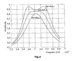
- this will be shown below at the resistor RD, where Fig. 4 shows the transfer function as a function of RD.
- the ultrasound device 10 operates in the receive mode like a (bandpass) filter, which is tunable according to the invention by an adjustment unit (to be explained below).
- the filter should have the widest possible bandwidth, as this determines the response time of the filter in the time domain and thus allows a good distance resolution.
- the bandwidth of the filter should be chosen so that it is not too wide, because otherwise noise and other sources of acoustic interference fall within the transmission range of the filter and are detected as an echo. If this resistor RD is not present, the impedance matching function of the circuit is still present, but optimization of the required bandwidth of the filter can not be achieved without a resistor RD connected in parallel with the transformer.
- the local maxima for the case RD ⁇ RD OPT or the local minima for the case RD> RD OPT are exactly at the resonance frequency of the entire system.
- the curve is right-curved in this case for the case RD ⁇ RD OPT , left-curved for RD> RD OPT .
- this means that the second derivative is less than zero for RD ⁇ RD OPT and greater than zero for RD> RD OPT .
- the second derivative is zero.
- y y - 1 - 2 ⁇ y 0 + y + 1 H 2 used.
- y 0 is the value of the transfer function at resonant frequency.
- Y -1 and Y +1 are two points to the left and right of it.
- the value of RD is increased in small steps until a sign change of the second derivative occurs. It has proved to be reliable, as a starting value for RD the value RO of the transducer too use. In the case of a faulty input and highly detuned oscillating circuits, an upper limit of RD of eg 100 * RO makes sense.
Landscapes
- Engineering & Computer Science (AREA)
- Mechanical Engineering (AREA)
- Transducers For Ultrasonic Waves (AREA)
- Measurement Of Resistance Or Impedance (AREA)
- Apparatuses For Generation Of Mechanical Vibrations (AREA)
Priority Applications (1)
| Application Number | Priority Date | Filing Date | Title |
|---|---|---|---|
| EP13196307.6A EP2881181A1 (fr) | 2013-12-09 | 2013-12-09 | Procédé de détermination de paramètres électriques d'un syntoniseur pour convertisseur à ultrasons |
Applications Claiming Priority (1)
| Application Number | Priority Date | Filing Date | Title |
|---|---|---|---|
| EP13196307.6A EP2881181A1 (fr) | 2013-12-09 | 2013-12-09 | Procédé de détermination de paramètres électriques d'un syntoniseur pour convertisseur à ultrasons |
Publications (1)
| Publication Number | Publication Date |
|---|---|
| EP2881181A1 true EP2881181A1 (fr) | 2015-06-10 |
Family
ID=49753032
Family Applications (1)
| Application Number | Title | Priority Date | Filing Date |
|---|---|---|---|
| EP13196307.6A Withdrawn EP2881181A1 (fr) | 2013-12-09 | 2013-12-09 | Procédé de détermination de paramètres électriques d'un syntoniseur pour convertisseur à ultrasons |
Country Status (1)
| Country | Link |
|---|---|
| EP (1) | EP2881181A1 (fr) |
Cited By (7)
| Publication number | Priority date | Publication date | Assignee | Title |
|---|---|---|---|---|
| CN109075760A (zh) * | 2016-04-25 | 2018-12-21 | 南洋理工大学 | 超声装置,其形成方法及其控制方法 |
| CN109877027A (zh) * | 2019-04-03 | 2019-06-14 | 淄博宇声计量科技有限公司 | 一种超声波换能器的阻抗匹配与收发功能切换电路 |
| US10585178B2 (en) | 2015-10-21 | 2020-03-10 | Semiconductor Componenents Industries, Llc | Piezo transducer controller and method having adaptively-tuned linear damping |
| CN111781470A (zh) * | 2020-06-05 | 2020-10-16 | 国网浙江省电力有限公司电力科学研究院 | 一种电流互感器的高频电路等效方法 |
| CN113594351A (zh) * | 2021-07-13 | 2021-11-02 | 杭州电子科技大学 | 一种谐振频率可调压电换能器及其频率调节控制系统 |
| CN116550585A (zh) * | 2022-01-13 | 2023-08-08 | 意法半导体股份有限公司 | 一种操作电声换能器的方法、相应的电路和装置 |
| DE102017120682B4 (de) * | 2016-09-08 | 2026-02-05 | Hyundai Mobis Co., Ltd. | Vorrichtung und verfahren zum betreiben eines ultraschallsensors |
Citations (6)
| Publication number | Priority date | Publication date | Assignee | Title |
|---|---|---|---|---|
| US3144764A (en) * | 1958-10-01 | 1964-08-18 | Republic Steel Corp | Ultrasonic inspection system |
| JP2001086587A (ja) * | 1999-09-10 | 2001-03-30 | Tokimec Inc | 超音波トランスデューサ |
| US20070121969A1 (en) * | 2005-11-15 | 2007-05-31 | Seiko Epson Corporation | Electrostatic transducer, driving circuit of capacitive load, method for setting circuit constant, ultrasonic speaker, display device and directional acoustic system |
| US20070121970A1 (en) * | 2005-11-25 | 2007-05-31 | Seiko Epson Corporation | Electrostatic transducer, ultrasonic speaker, driving circuit of capacitive load, method of setting circuit constant, display device, and directional sound system |
| US20110261652A1 (en) * | 2010-04-26 | 2011-10-27 | Pavel Horsky | Self-tuning acoustic measurement system |
| US20130093522A1 (en) * | 2011-10-12 | 2013-04-18 | Atmel Corporation | High accuracy rc oscillator |
-
2013
- 2013-12-09 EP EP13196307.6A patent/EP2881181A1/fr not_active Withdrawn
Patent Citations (6)
| Publication number | Priority date | Publication date | Assignee | Title |
|---|---|---|---|---|
| US3144764A (en) * | 1958-10-01 | 1964-08-18 | Republic Steel Corp | Ultrasonic inspection system |
| JP2001086587A (ja) * | 1999-09-10 | 2001-03-30 | Tokimec Inc | 超音波トランスデューサ |
| US20070121969A1 (en) * | 2005-11-15 | 2007-05-31 | Seiko Epson Corporation | Electrostatic transducer, driving circuit of capacitive load, method for setting circuit constant, ultrasonic speaker, display device and directional acoustic system |
| US20070121970A1 (en) * | 2005-11-25 | 2007-05-31 | Seiko Epson Corporation | Electrostatic transducer, ultrasonic speaker, driving circuit of capacitive load, method of setting circuit constant, display device, and directional sound system |
| US20110261652A1 (en) * | 2010-04-26 | 2011-10-27 | Pavel Horsky | Self-tuning acoustic measurement system |
| US20130093522A1 (en) * | 2011-10-12 | 2013-04-18 | Atmel Corporation | High accuracy rc oscillator |
Cited By (10)
| Publication number | Priority date | Publication date | Assignee | Title |
|---|---|---|---|---|
| US10585178B2 (en) | 2015-10-21 | 2020-03-10 | Semiconductor Componenents Industries, Llc | Piezo transducer controller and method having adaptively-tuned linear damping |
| CN109075760A (zh) * | 2016-04-25 | 2018-12-21 | 南洋理工大学 | 超声装置,其形成方法及其控制方法 |
| CN109075760B (zh) * | 2016-04-25 | 2024-04-02 | 南洋理工大学 | 超声装置,其形成方法及其控制方法 |
| DE102017120682B4 (de) * | 2016-09-08 | 2026-02-05 | Hyundai Mobis Co., Ltd. | Vorrichtung und verfahren zum betreiben eines ultraschallsensors |
| CN109877027A (zh) * | 2019-04-03 | 2019-06-14 | 淄博宇声计量科技有限公司 | 一种超声波换能器的阻抗匹配与收发功能切换电路 |
| CN109877027B (zh) * | 2019-04-03 | 2024-01-26 | 淄博宇声计量科技有限公司 | 一种超声波换能器的阻抗匹配与收发功能切换电路 |
| CN111781470A (zh) * | 2020-06-05 | 2020-10-16 | 国网浙江省电力有限公司电力科学研究院 | 一种电流互感器的高频电路等效方法 |
| CN111781470B (zh) * | 2020-06-05 | 2023-05-16 | 国网浙江省电力有限公司电力科学研究院 | 一种电流互感器的高频电路等效方法 |
| CN113594351A (zh) * | 2021-07-13 | 2021-11-02 | 杭州电子科技大学 | 一种谐振频率可调压电换能器及其频率调节控制系统 |
| CN116550585A (zh) * | 2022-01-13 | 2023-08-08 | 意法半导体股份有限公司 | 一种操作电声换能器的方法、相应的电路和装置 |
Similar Documents
| Publication | Publication Date | Title |
|---|---|---|
| EP2984503B1 (fr) | Procédé de mesure par ultrason, notamment comme aide au stationnement pour véhicules, et systèmes de mesure par ultrason | |
| EP2743725B1 (fr) | Dispositif à ultrasons | |
| DE2005918A1 (de) | Siebschaltung | |
| EP1837893A1 (fr) | Dispositif de mesure d'un système plasma HF | |
| DE2404878A1 (de) | Akustischer oberflaechenwandler | |
| DE2724437C2 (fr) | ||
| DE1566035A1 (de) | Akustische Vorrichtung | |
| DE1953826A1 (de) | Energieuebertragungseinrichtung | |
| DE2803225A1 (de) | Temperaturabtastsystem | |
| DE102010003624A1 (de) | Verfahren zum Erfassen einer Störung eines Ultraschallwandlers und Störungserfassungsvorrichtung für einen Ultraschallwandler | |
| DE1957765A1 (de) | Brueckenfilter | |
| EP2243219B1 (fr) | Filtre optimal numérique pour signaux d'alternance périodique | |
| EP1736748B1 (fr) | Procédé de traitement du signal de sortie d'un capteur de mesure et dispositif de mesure de force servant à la mise en oeuvre de ce procédé. | |
| EP1458216B1 (fr) | Appareil et procédé à l'adaption de microphones dans une prothèse auditive | |
| DE102014213122B4 (de) | Vorrichtung und Verfahren zur schallbasierten Umfelddetektion | |
| WO2012100959A1 (fr) | Dispositif cylindrique, système de mesure de la vitesse de l'onde de pouls et procédé de mesure de la vitesse de l'onde de pouls | |
| EP3537177B1 (fr) | Dispositif et procédé de commande sans transformateur d'un transducteur ultrasonore | |
| DE102022115293B4 (de) | Hybridfilterschaltung und System mit Hybridfilterschaltung | |
| DE10103481A1 (de) | Quasi-Peak-Detektor | |
| WO2007082834A1 (fr) | Appareil de mesure, notamment appareil de mesure de distance | |
| EP2904424B1 (fr) | Suppression de l'oscillation d'un convertisseur pour la détection environnementale | |
| EP2725353B1 (fr) | Procédé de réglage automatique du point de travail de fréquence d'exploitation d'un dispositif de détection à ultrasons | |
| EP2154492A1 (fr) | Dispositif de mesure de débit à ultrasons doté d'une augmentation de tension LC | |
| EP1762945B1 (fr) | Procédé pour transformer dans le domaine temporel des données mesurées obtenues dans le domaine fréquentiel | |
| AT510244B1 (de) | Schnelles messverfahren zur erfassung von ofw-sensordaten |
Legal Events
| Date | Code | Title | Description |
|---|---|---|---|
| PUAI | Public reference made under article 153(3) epc to a published international application that has entered the european phase |
Free format text: ORIGINAL CODE: 0009012 |
|
| 17P | Request for examination filed |
Effective date: 20150417 |
|
| AK | Designated contracting states |
Kind code of ref document: A1 Designated state(s): AL AT BE BG CH CY CZ DE DK EE ES FI FR GB GR HR HU IE IS IT LI LT LU LV MC MK MT NL NO PL PT RO RS SE SI SK SM TR |
|
| RAP1 | Party data changed (applicant data changed or rights of an application transferred) |
Owner name: ELMOS SEMICONDUCTOR AKTIENGESELLSCHAFT |
|
| RAP1 | Party data changed (applicant data changed or rights of an application transferred) |
Owner name: ELMOS SEMICONDUCTOR AKTIENGESELLSCHAFT |
|
| 17Q | First examination report despatched |
Effective date: 20160314 |
|
| STAA | Information on the status of an ep patent application or granted ep patent |
Free format text: STATUS: EXAMINATION IS IN PROGRESS |
|
| STAA | Information on the status of an ep patent application or granted ep patent |
Free format text: STATUS: THE APPLICATION IS DEEMED TO BE WITHDRAWN |
|
| 18D | Application deemed to be withdrawn |
Effective date: 20170315 |