EP2881602A1 - Joint à rotule - Google Patents
Joint à rotule Download PDFInfo
- Publication number
- EP2881602A1 EP2881602A1 EP13825733.2A EP13825733A EP2881602A1 EP 2881602 A1 EP2881602 A1 EP 2881602A1 EP 13825733 A EP13825733 A EP 13825733A EP 2881602 A1 EP2881602 A1 EP 2881602A1
- Authority
- EP
- European Patent Office
- Prior art keywords
- unit
- stud
- dust cover
- diameter opening
- small diameter
- Prior art date
- Legal status (The legal status is an assumption and is not a legal conclusion. Google has not performed a legal analysis and makes no representation as to the accuracy of the status listed.)
- Withdrawn
Links
- 230000002093 peripheral effect Effects 0.000 claims abstract description 116
- 239000000428 dust Substances 0.000 claims abstract description 109
- 230000003014 reinforcing effect Effects 0.000 claims abstract description 79
- 238000007789 sealing Methods 0.000 claims abstract description 57
- 238000004891 communication Methods 0.000 claims description 2
- 239000010408 film Substances 0.000 description 19
- 239000013013 elastic material Substances 0.000 description 17
- 238000000465 moulding Methods 0.000 description 15
- 238000000034 method Methods 0.000 description 11
- 229910052751 metal Inorganic materials 0.000 description 9
- 239000002184 metal Substances 0.000 description 9
- 239000011347 resin Substances 0.000 description 7
- 229920005989 resin Polymers 0.000 description 7
- 239000000463 material Substances 0.000 description 5
- 230000008878 coupling Effects 0.000 description 4
- 238000010168 coupling process Methods 0.000 description 4
- 238000005859 coupling reaction Methods 0.000 description 4
- 230000014509 gene expression Effects 0.000 description 4
- 230000007246 mechanism Effects 0.000 description 4
- 230000001105 regulatory effect Effects 0.000 description 4
- 230000008569 process Effects 0.000 description 3
- 239000010409 thin film Substances 0.000 description 3
- 238000010137 moulding (plastic) Methods 0.000 description 2
- 239000011435 rock Substances 0.000 description 2
- XLYOFNOQVPJJNP-UHFFFAOYSA-N water Substances O XLYOFNOQVPJJNP-UHFFFAOYSA-N 0.000 description 2
- 229910052782 aluminium Inorganic materials 0.000 description 1
- XAGFODPZIPBFFR-UHFFFAOYSA-N aluminium Chemical compound [Al] XAGFODPZIPBFFR-UHFFFAOYSA-N 0.000 description 1
- 230000015556 catabolic process Effects 0.000 description 1
- 239000011248 coating agent Substances 0.000 description 1
- 238000000576 coating method Methods 0.000 description 1
- 238000006731 degradation reaction Methods 0.000 description 1
- 230000001771 impaired effect Effects 0.000 description 1
- 238000012986 modification Methods 0.000 description 1
- 230000004048 modification Effects 0.000 description 1
- 239000000725 suspension Substances 0.000 description 1
Images


Classifications
-
- F—MECHANICAL ENGINEERING; LIGHTING; HEATING; WEAPONS; BLASTING
- F16—ENGINEERING ELEMENTS AND UNITS; GENERAL MEASURES FOR PRODUCING AND MAINTAINING EFFECTIVE FUNCTIONING OF MACHINES OR INSTALLATIONS; THERMAL INSULATION IN GENERAL
- F16C—SHAFTS; FLEXIBLE SHAFTS; ELEMENTS OR CRANKSHAFT MECHANISMS; ROTARY BODIES OTHER THAN GEARING ELEMENTS; BEARINGS
- F16C11/00—Pivots; Pivotal connections
- F16C11/04—Pivotal connections
- F16C11/06—Ball-joints; Other joints having more than one degree of angular freedom, i.e. universal joints
- F16C11/0666—Sealing means between the socket and the inner member shaft
- F16C11/0671—Sealing means between the socket and the inner member shaft allowing operative relative movement of joint parts due to flexing of the sealing means
-
- F—MECHANICAL ENGINEERING; LIGHTING; HEATING; WEAPONS; BLASTING
- F16—ENGINEERING ELEMENTS AND UNITS; GENERAL MEASURES FOR PRODUCING AND MAINTAINING EFFECTIVE FUNCTIONING OF MACHINES OR INSTALLATIONS; THERMAL INSULATION IN GENERAL
- F16J—PISTONS; CYLINDERS; SEALINGS
- F16J15/00—Sealings
- F16J15/16—Sealings between relatively-moving surfaces
-
- F—MECHANICAL ENGINEERING; LIGHTING; HEATING; WEAPONS; BLASTING
- F16—ENGINEERING ELEMENTS AND UNITS; GENERAL MEASURES FOR PRODUCING AND MAINTAINING EFFECTIVE FUNCTIONING OF MACHINES OR INSTALLATIONS; THERMAL INSULATION IN GENERAL
- F16J—PISTONS; CYLINDERS; SEALINGS
- F16J15/00—Sealings
- F16J15/50—Sealings between relatively-movable members, by means of a sealing without relatively-moving surfaces, e.g. fluid-tight sealings for transmitting motion through a wall
- F16J15/52—Sealings between relatively-movable members, by means of a sealing without relatively-moving surfaces, e.g. fluid-tight sealings for transmitting motion through a wall by means of sealing bellows or diaphragms
-
- F—MECHANICAL ENGINEERING; LIGHTING; HEATING; WEAPONS; BLASTING
- F16—ENGINEERING ELEMENTS AND UNITS; GENERAL MEASURES FOR PRODUCING AND MAINTAINING EFFECTIVE FUNCTIONING OF MACHINES OR INSTALLATIONS; THERMAL INSULATION IN GENERAL
- F16C—SHAFTS; FLEXIBLE SHAFTS; ELEMENTS OR CRANKSHAFT MECHANISMS; ROTARY BODIES OTHER THAN GEARING ELEMENTS; BEARINGS
- F16C11/00—Pivots; Pivotal connections
- F16C11/04—Pivotal connections
- F16C11/06—Ball-joints; Other joints having more than one degree of angular freedom, i.e. universal joints
- F16C11/0619—Ball-joints; Other joints having more than one degree of angular freedom, i.e. universal joints the female part comprising a blind socket receiving the male part
-
- Y—GENERAL TAGGING OF NEW TECHNOLOGICAL DEVELOPMENTS; GENERAL TAGGING OF CROSS-SECTIONAL TECHNOLOGIES SPANNING OVER SEVERAL SECTIONS OF THE IPC; TECHNICAL SUBJECTS COVERED BY FORMER USPC CROSS-REFERENCE ART COLLECTIONS [XRACs] AND DIGESTS
- Y10—TECHNICAL SUBJECTS COVERED BY FORMER USPC
- Y10T—TECHNICAL SUBJECTS COVERED BY FORMER US CLASSIFICATION
- Y10T403/00—Joints and connections
- Y10T403/32—Articulated members
- Y10T403/32606—Pivoted
- Y10T403/32631—Universal ball and socket
- Y10T403/32729—Externally packed
Definitions
- This dust cover for a ball joint to be used for a suspension mechanism and a steering mechanism for a vehicle, for example, such a dust cover described in Patent Document 1 has been known.
- This dust cover is made of a rubber-state elastic member, and constituted by a small diameter opening unit to be fitted to an outer peripheral surface of a ball stud, a large diameter opening unit to be fitted to an outer peripheral surface of a socket and a film unit that connects the gap between these surfaces, and a reinforcing ring is buried in the small diameter opening unit.
- Patent Document 1 JP-A No. 2009-14064
- the dust cover has a difference between the outer radius of the stud unit and the inner radius of the sealing unit in the unattached state as a tightening margin, and a difference between the outer radius of the stud unit and the inner radius of the guide unit as a fine gap, and the tightening margin is made wider than the fine gap.
- the tightening margin of the sealing unit is larger than the amount of the gap in the radial direction (fine gap) of the guide unit, it becomes possible to maintain the state of the sealing unit provided with the tightening margin, even in the case when the small diameter opening unit is tilted so that one portion of the inner peripheral surface of the guide unit is made in contact with the outer peripheral portion of the stud unit, and consequently to maintain a good sealing property of the dust cover even in the case when the small diameter opening unit is tilted to the maximum level.
- the inner peripheral protruding unit having an elastic property, it is possible to increase a force resisting the small diameter opening unit from being tilted, while maintaining the freely sliding property of the small diameter opening unit relative to the stud unit, and even when the force by which the small diameter opening unit is pulled by the film unit is the same, the tilt angle of the small diameter opening unit can be suppressed to a smaller angle so that the sealing endurance of the dust cover can be improved.
- the groove on the inner peripheral surface that is made face to face with the guide unit of the reinforcing ring it becomes possible to maintain a flowing path for use in filling an elastic material such as rubber around the reinforcing ring, upon molding the dust cover with the reinforcing ring being inserted, and also to make the inner peripheral surface of the reinforcing ring closer to the inner peripheral surface of the guide unit; thus, even in the case when a thin film of an elastic member, such as rubber, is required to be placed between the inner peripheral surface of the guide unit and the inner peripheral surface of the reinforcing ring due to conditions or the like of the moldability of the dust cover, the rigidity of the guide unit is enhanced so that a good sealing property of the dust cover can be ensured.
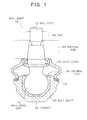
- FIG. 1 is an explanatory view showing a configuration of a ball joint of a first embodiment in accordance with the present invention.
- a ball joint 10 is constituted by a ball stud 12, a ball sheet 30, a socket 32 and a dust cover 36, and is assembled onto a knuckle arm 80 serving as an assembling target by a nut 82.
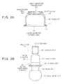
- FIGS. 2A and 2B are explanatory views showing the dust cover 36 and the ball stud 12 respectively in a separated manner
- FIG. 2A is a cross-sectional view of the dust cover 36
- FIG. 2B shows the ball stud 12.
- the dust cover 36 formed by an elastic material, such as rubber, is provided with a small diameter opening unit 40 formed on the upper end of the film unit 38 and a large diameter opening unit 70 formed on the lower end thereof, and a reinforcing ring 56, which is formed by a resin, metal and the like, is embedded into the small diameter opening unit 40, and into the large diameter opening unit 70, a peripheral edge unit 72 having a press-in ring 74 made of metal being embedded therein, is formed.
- the press-in ring 74 is embedded into the large diameter opening unit 70, and as shown in FIG. 1 , the dust cover 36 is secured onto the socket 32, with its rigidity being maintained by the press-in ring 74; however, as the attaching mode of the dust cover 36 onto the socket 32 side, another mode may be used.
- a tube-shaped unit 58 and a flange-shaped unit 60 are formed on the reinforcing ring 56, and in the present embodiment, the inner peripheral surface 60a of the flange unit 60 and the lower end surface 58a of the tube-shaped unit 58 are exposed from an elastic material, such as rubber, that forms the dust cover 36 so that the inner peripheral surface 60a forms the guide unit 44 and the lower end surface 58a forms the engaging unit 54.
- the lip unit 48 is formed; however, in some cases, the lip unit 48 is not necessarily formed depending on the condition or the like of the component shape of the assembling target.
- the sealing unit 46 at a position (between the guide unit 44 and the engaging unit 54) lower than the guide unit 44, the distance between the two position regulating units, that is, the guide unit 44 and the engaging unit 54, can be made longer; therefore, the tilt of the small diameter opening unit 40 relative to the fine gap between the stud unit 14 and the guide unit 44 can be suppressed to a smaller level.
- the ball stud 12 When the ball joint 10 is activated, the ball stud 12 carries out rocking and sliding movements on the socket 32.
- the rocking movements refer to operations in which the ball stud 12 is tilted around the center point of the ball-head unit 16
- the sliding movements refer to operations in which the ball stud 12 is rotated around the center axis of the stud unit 14.
- the small diameter opening unit 40 In the dust cover 36, in order to prevent the film unit 38 of the dust cover 36 from being twisted and damaged due to sliding movements of the ball stud 12 at the time when the small diameter opening unit 40 is attached to the ball stud 12, while the large diameter opening unit 70 is attached to the socket 32, the small diameter opening unit 40 needs to be tightly made in contact with the ball stud 12 so as to be freely slidable thereon.
- the reinforcing ring 56 When insert-molded as the dust cover 36, the reinforcing ring 56 allows the inner peripheral surface 60a of the flange unit 60 to form the guide unit 44 and the lower end surface 58a in the axial direction of the tube-shaped unit 58 to form the engaging unit 54, and since the reinforcing ring 56 is made of a material such as a resin or metal with rigidity that is sufficiently higher than the material such as rubber to be used for the elastic portion of the dust cover, the guide unit 44 and the engaging unit 54 are coupled to each other with high rigidity.
- FIG. 5A and FIG. 5B are explanatory views showing a relationship between a fine gap and a tightening margin of the small diameter opening unit 40 of the dust cover 36 in the first embodiment
- FIG. 5A shows the dust cover 36 in an unattached state
- FIG. 5B shows a state in which the small diameter opening unit 40 of the dust cover 36 is attached between the upper surface 20a of the flange unit and the lower surface 80a of the knuckle arm of the ball stud 12, as shown in FIG. 1 .
- the small diameter opening unit 40 allows the inner peripheral portion 60a of the reinforcing ring 56 that is formed into the guide unit 44 to be fitted to the outer peripheral surface 26 of the shaft unit 22, with a fine gap Cm in the radial direction being placed, and also allows the lower end portion 58a of the reinforcing ring 56 that is formed into the engaging unit 54 to be made in contact with the upper surface 20a of the flange unit and engaged therewith.
- an inner diameter of the sealing unit 46 in an unattached stat is Ds
- an outer diameter of the shaft unit 22 is Do
- an inner diameter of the guide unit 44 is Dg
- the tightening margin Ci corresponds to a difference between the outer radius (Do/2) of the shaft unit 22 and the inner radius (Ds/2) of the sealing unit 46 in an unattached state
- the fine gap Cm corresponds to a difference between the outer radius (Do/2) of the shaft unit 22 and the inner radius (Dg/2) of the guide unit 44
- the tightening margin Ci becomes larger than the fine gap Cm.
- the dislocation in the radial direction of the inner peripheral portion 42 caused by the tilt of the small diameter opening unit 40 is smaller in the sealing unit 46 located below the guide unit 44 than that in the guide unit 44.
- the sealing unit 46 By setting the tightening margin Ci of the sealing unit 46 so as to be larger than the amount of the gap (fine gap Cm) in the radial direction of the guide unit 44, even in the case when the small diameter opening unit 40 is tilted until one portion of the inner peripheral surface 60a of the guide unit 44 comes into contact with the outer peripheral surface 26 of the shaft unit 22, the sealing unit 46 is allowed to maintain the state having the tightening margin. Additionally, the tightening margin in the state with the small diameter opening unit 40 being tilted becomes actually smaller than the tightening margin Ci in the initial state.
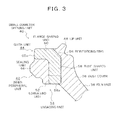
- FIG. 6 is an explanatory view showing a structure of a second embodiment of a ball joint in accordance with the present invention.
- a ball joint 110 is constituted by a ball stud 112, a retainer 120, a ball sheet 130, a socket 132, a dust cover 136, a clamp 174 and a plug 180, and is secured onto a knuckle arm 80 serving as an assembling target by a nut 82.
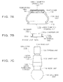
- FIGS. 7A, 7B and 7C are explanatory views showing the dust cover 136, the retainer 120 and the ball stud 112 respectively in a separated manner
- FIG. 7A is a cross-sectional view of the dust cover 136
- FIG. 7B is a cross-sectional view of the retainer 120
- FIG. 7C shows the ball stud 112.
- the retainer 120 forms a cylinder unit 120a and a flange unit 120c, and in a state where the cylinder unit 120a is press-inserted onto the outer peripheral surface 126 of the shaft unit 122 and secured thereto, the flange unit 120c corresponds to the flange unit 20 of the ball stud 12 of the first embodiment.
- the outer peripheral surface 120b of the cylinder unit 120a replaces the outer peripheral surface 26 of the shaft unit 22 of the first embodiment
- the upper surface 120d of the flange unit 120c replaces the flange unit upper surface 20a in the first embodiment.
- the attaching method of the dust cover 136 onto the ball stud 112 side may be carried out by another securing method as long as the same structure is provided, and the assembling target for the ball joint 110 may be desirably determined.
- FIG. 8 is a cross-sectional view showing the small diameter opening unit 140 of the dust cover 136 of the second embodiment in an enlarged manner, which corresponds to the portion on the right side of the small diameter opening unit 140 in FIG. 7A that is drawn out and shown.
- the small diameter opening unit 140 has a structure in which a guide unit 144, a sealing unit 146 and an inner peripheral protruding unit 150 are formed on the inner peripheral portion 142 side, and a lip unit 48 is formed on the upper end side, with an engaging unit 154 being formed on a lower end unit 152 side, and the reinforcing ring 156 is embedded inside thereof.
- the present embodiment exemplifies a case in which the inner peripheral surface 160a and the lower end surface 158a of the reinforcing ring 156 are covered with a thin film of an elastic material (material forming a dust cover), such as rubber, with these coated surfaces forming the guide unit 144 and the engaging unit 154.
- an elastic material material forming a dust cover
- the guide unit 144 is fitted to the outer peripheral surface 126 of the shaft unit 122, with a fine gap being formed in the radial direction, and the engaging unit 154 is made in contact with the flange unit upper surface 120d of the retainer 120 in the axial direction and engaged therewith.
- the sealing unit 146 is made tightly in contact with the outer peripheral surface 126 of the shaft unit 122 by a tightening margin in the radial direction so that the sealing property of the small diameter opening unit 140 is maintained.
- FIGS. 10A and 10B are explanatory views showing a relationship between the fine gap and the tightening margin of the small diameter opening unit 140 of the dust cover 136 in the second embodiment
- FIG. 10A shows an unattached state of the dust cover 136
- FIG. 10B shows a state in which, as shown in FIG. 6 , the small diameter opening unit 140 of the dust cover 136 is attached between the flange-unit upper surface 120d of the retainer 120 and the knuckle-arm lower surface 80a.
- an inner diameter of the sealing unit 146 in an unattached state is Ds
- an outer diameter (outer diameter of the shaft unit) of the retainer outer peripheral surface 120b is Do
- an inner diameter of the guide unit 144 is Dg
- a structure is made so as to allow relationships between the fine gap Cm and the outer peripheral surface 120b of the guide unit 144 as well as between the tightening margin Ci and the outer peripheral surface 120b of the sealing unit 146 to satisfy the following expressions:
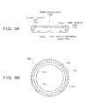
- a small diameter opening unit 240 of a dust cover 236 has a structure in which a guide unit 244, a sealing unit 246 and an inner peripheral protruding unit 250 are formed on the inner peripheral portion 242 side, and a lip unit 248 is formed on the upper end side and an engaging unit 254 is formed on the lower end unit 252 side, with a reinforcing ring 256 formed with a resin or the like being embedded inside thereof.
- FIGS. 12A and 12B are explanatory views showing the reinforcing ring 256 of FIG. 11 in detail, FIG. 12A shows a cross section of the reinforcing ring 256, and FIG. 12B shows a lower side plane of the reinforcing ring 256.
- FIGS. 12A and 12B are explanatory views showing the reinforcing ring 256 of FIG. 11 in detail, FIG. 12A shows a cross section of the reinforcing ring 256, and FIG. 12B shows a lower side plane of the reinforcing ring 256.
- the shape, the size and the number of the grooves (radial-direction grooves 262 and axial-direction grooves 264) of the reinforcing ring 256 may be desirably set within a range not intervening with the flow of the elastic material such as rubber at the time of molding the dust cover 236, and these are not limited by the mode shown in FIG. 12 . These are also applied to the other embodiments in the same manner.
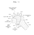
- a small diameter opening unit 340 of a dust cover 336 has a structure in which a guide unit 344, a sealing unit 346 and an inner peripheral protruding unit 350 are formed on the inner peripheral portion 342 side, and a lip unit 348 is formed on the upper end side, with an engaging unit 354 being formed on a lower end unit 352 side, and a reinforcing ring 356 formed by press working of a sheet metal is embedded inside thereof.
- a tube-shaped unit 358 and a flange-shaped unit 360 are formed on the reinforcing ring 356, and in the present embodiment, the lower end surface 358a of the tube-shaped unit 358 is exposed from an elastic material, such as rubber, that forms the dust cover 336 so that an engaging unit 354 is formed, and the inner peripheral surface 360a of the flange-shaped unit 360 is not exposed and is disposed at a position facing the inner peripheral surface of the guide unit 344.
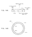
- FIGS. 14A and 14B are explanatory views showing the reinforcing ring 356 of FIG. 13 in detail
- FIG. 14A shows a cross section of the reinforcing ring 356, and
- FIG. 14B shows a lower side plane of the reinforcing ring 356.
- the reinforcing ring 356 has a structure in which the tube-shaped unit 358 and the flange-shaped unit 360 are formed by press working of a sheet metal, and on the tube-shaped unit 358, a plurality of radial-direction holes 362 for use in flowing an elastic material such as rubber at the time of molding the dust cover 336 are formed.
- FIG. 15 is a cross-sectional view showing a small diameter opening unit of a dust cover of a fifth embodiment in an enlarged manner, and the structure is the same as the dust cover 136 of the second embodiment shown in FIG. 8 , except that the shape of one portion of each of the reinforcing ring and the dust cover main body is different.
- a small diameter opening unit 440 of a dust cover 436 has a structure in which a guide unit 444, a sealing unit 446 and an inner peripheral protruding unit 450 are formed on the inner peripheral portion 442 side, and an engaging unit 454 is formed on a lower end unit 452 side, and a reinforcing ring 456 made of metal or a resin is embedded inside thereof.
- the upper end surface 458b and the upper outer peripheral surface 458c of the tube-shaped unit 458 are exposed, and the upper outer peripheral surface 458c forms a positioning unit for holding the reinforcing ring 456 inside the mold at the time of molding the dust cover 436.
- the present invention is also applicable to all kinds of ball joints provided with a dust cover, and not limited to the above-mentioned embodiments, modifications may be made therein on demand within a range without impairing its objects and advantages.
Landscapes
- Engineering & Computer Science (AREA)
- General Engineering & Computer Science (AREA)
- Mechanical Engineering (AREA)
- Pivots And Pivotal Connections (AREA)
- Sealing Devices (AREA)
Applications Claiming Priority (2)
| Application Number | Priority Date | Filing Date | Title |
|---|---|---|---|
| JP2012168163 | 2012-07-30 | ||
| PCT/JP2013/065003 WO2014020980A1 (fr) | 2012-07-30 | 2013-05-30 | Joint à rotule |
Publications (2)
| Publication Number | Publication Date |
|---|---|
| EP2881602A1 true EP2881602A1 (fr) | 2015-06-10 |
| EP2881602A4 EP2881602A4 (fr) | 2016-05-11 |
Family
ID=50027671
Family Applications (1)
| Application Number | Title | Priority Date | Filing Date |
|---|---|---|---|
| EP13825733.2A Withdrawn EP2881602A4 (fr) | 2012-07-30 | 2013-05-30 | Joint à rotule |
Country Status (4)
| Country | Link |
|---|---|
| US (1) | US20150030376A1 (fr) |
| EP (1) | EP2881602A4 (fr) |
| JP (1) | JP5941547B2 (fr) |
| WO (1) | WO2014020980A1 (fr) |
Cited By (1)
| Publication number | Priority date | Publication date | Assignee | Title |
|---|---|---|---|---|
| EP3015725A4 (fr) * | 2013-06-25 | 2016-07-13 | Nok Corp | Couvercle anti-poussière de rotule |
Families Citing this family (13)
| Publication number | Priority date | Publication date | Assignee | Title |
|---|---|---|---|---|
| DE102011084163A1 (de) * | 2011-10-07 | 2013-04-11 | Zf Friedrichshafen Ag | Verbindungsanordnung für ein Fahrzeug |
| US10527088B2 (en) * | 2014-08-21 | 2020-01-07 | Nok Corporation | Dust cover |
| EP3211278B1 (fr) * | 2014-10-22 | 2019-09-18 | Nok Corporation | Capot antipoussière |
| DE102015210960A1 (de) * | 2015-04-17 | 2016-08-25 | Hecht Technologie Gmbh | Flexibles Verbindungselement zur Verbindung einer ersten Einrichtung mit einer zweiten Einrichtung, insbesondere Waagenkompensator |
| US9790983B2 (en) * | 2015-05-21 | 2017-10-17 | Federal-Mogul Motorparts Corporation | Movable joint assembly |
| WO2017061212A1 (fr) * | 2015-10-05 | 2017-04-13 | Nok株式会社 | Couvercle anti-poussière |
| JP6711581B2 (ja) * | 2015-10-07 | 2020-06-17 | Thkリズム株式会社 | ボールジョイント |
| CN108700109A (zh) * | 2016-03-10 | 2018-10-23 | Nok株式会社 | 防尘罩以及密封构造 |
| DE102018000128B4 (de) * | 2018-01-10 | 2021-06-24 | Carl Freudenberg Kg | Dichtungsbalg |
| KR102729096B1 (ko) * | 2019-03-13 | 2024-11-13 | 엘지전자 주식회사 | 로봇 |
| JP7400482B2 (ja) * | 2020-01-15 | 2023-12-19 | Nok株式会社 | ダストカバーおよびボールジョイント |
| JPWO2021215363A1 (fr) * | 2020-04-22 | 2021-10-28 | ||
| CN113819238A (zh) * | 2021-08-31 | 2021-12-21 | 岚图汽车科技有限公司 | 一种轮毂轴承端部的密封结构及汽车 |
Family Cites Families (13)
| Publication number | Priority date | Publication date | Assignee | Title |
|---|---|---|---|---|
| JPS61175667U (fr) * | 1985-04-22 | 1986-11-01 | ||
| JPH0299006U (fr) * | 1989-01-27 | 1990-08-07 | ||
| JPH03123161U (fr) * | 1990-03-28 | 1991-12-16 | ||
| JPH044520U (fr) * | 1990-04-27 | 1992-01-16 | ||
| JPH044521U (fr) * | 1990-04-27 | 1992-01-16 | ||
| JPH078905Y2 (ja) * | 1990-07-13 | 1995-03-06 | 武蔵精密工業株式会社 | ボールジョイント |
| JPH0484823U (fr) * | 1990-11-29 | 1992-07-23 | ||
| JPH0558942U (ja) * | 1992-01-17 | 1993-08-03 | 豊田合成株式会社 | ダストカバー |
| JP2598458Y2 (ja) * | 1993-10-01 | 1999-08-09 | 株式会社オティックス | ボールジョイントのダストカバー |
| JP4868185B2 (ja) * | 2006-10-13 | 2012-02-01 | Nok株式会社 | ダストカバー用固定金具 |
| JP2009014064A (ja) * | 2007-07-03 | 2009-01-22 | Nok Corp | ボールジョイント用ダストカバー |
| JP5057219B2 (ja) * | 2007-07-09 | 2012-10-24 | Nok株式会社 | ボールジョイント用ダストカバー |
| JP2009024834A (ja) * | 2007-07-23 | 2009-02-05 | Nok Corp | ボールジョイント用ダストカバー |
-
2013
- 2013-05-30 JP JP2014528030A patent/JP5941547B2/ja active Active
- 2013-05-30 WO PCT/JP2013/065003 patent/WO2014020980A1/fr not_active Ceased
- 2013-05-30 EP EP13825733.2A patent/EP2881602A4/fr not_active Withdrawn
-
2014
- 2014-10-15 US US14/514,648 patent/US20150030376A1/en not_active Abandoned
Cited By (1)
| Publication number | Priority date | Publication date | Assignee | Title |
|---|---|---|---|---|
| EP3015725A4 (fr) * | 2013-06-25 | 2016-07-13 | Nok Corp | Couvercle anti-poussière de rotule |
Also Published As
| Publication number | Publication date |
|---|---|
| US20150030376A1 (en) | 2015-01-29 |
| EP2881602A4 (fr) | 2016-05-11 |
| JPWO2014020980A1 (ja) | 2016-07-21 |
| WO2014020980A1 (fr) | 2014-02-06 |
| JP5941547B2 (ja) | 2016-06-29 |
Similar Documents
| Publication | Publication Date | Title |
|---|---|---|
| EP2881602A1 (fr) | Joint à rotule | |
| EP3211278B1 (fr) | Capot antipoussière | |
| CN104541075B (zh) | 球窝接头用防尘罩 | |
| US9084352B2 (en) | Lid member with waterproofing function | |
| KR101829945B1 (ko) | 스태빌라이저 링크 및 그 제조 방법 | |
| WO2016190385A1 (fr) | Joint à rotule | |
| US20100133758A1 (en) | Sealing device | |
| US10626943B2 (en) | Grommet | |
| CN102725544A (zh) | 球窝接头 | |
| CN106687700A (zh) | 防尘罩 | |
| JP2007153298A (ja) | タイヤバルブユニット | |
| US20210033141A1 (en) | Dust cover | |
| US20160281771A1 (en) | Dust cover for ball joint | |
| WO2017018168A1 (fr) | Capuchon anti-poussière pour joint à rotule | |
| US20090205167A1 (en) | Snap Assembly Friction Hinge | |
| US9746081B2 (en) | Low load offset seal | |
| JP6964201B2 (ja) | ボールジョイント及びダストカバー | |
| WO2017154672A1 (fr) | Capot anti-poussière et structure d'étanchéité | |
| JP2017072184A (ja) | ボールジョイント | |
| CN208236888U (zh) | 防尘罩 | |
| CN107002744B (zh) | 球节及其壳体 | |
| JP2007239970A (ja) | ボールジョイント用ダストカバー | |
| JP2016044737A (ja) | ボールジョイント | |
| JP2013024385A (ja) | ボールジョイントの取付構造 | |
| US20250183601A1 (en) | Relay connector |
Legal Events
| Date | Code | Title | Description |
|---|---|---|---|
| PUAI | Public reference made under article 153(3) epc to a published international application that has entered the european phase |
Free format text: ORIGINAL CODE: 0009012 |
|
| 17P | Request for examination filed |
Effective date: 20141016 |
|
| AK | Designated contracting states |
Kind code of ref document: A1 Designated state(s): AL AT BE BG CH CY CZ DE DK EE ES FI FR GB GR HR HU IE IS IT LI LT LU LV MC MK MT NL NO PL PT RO RS SE SI SK SM TR |
|
| AX | Request for extension of the european patent |
Extension state: BA ME |
|
| DAX | Request for extension of the european patent (deleted) | ||
| RA4 | Supplementary search report drawn up and despatched (corrected) |
Effective date: 20160411 |
|
| RIC1 | Information provided on ipc code assigned before grant |
Ipc: F16J 15/16 20060101ALN20160405BHEP Ipc: F16J 15/52 20060101ALN20160405BHEP Ipc: F16C 11/06 20060101AFI20160405BHEP |
|
| STAA | Information on the status of an ep patent application or granted ep patent |
Free format text: STATUS: THE APPLICATION IS DEEMED TO BE WITHDRAWN |
|
| 18D | Application deemed to be withdrawn |
Effective date: 20161110 |