EP2881621A2 - Actionneur - Google Patents
Actionneur Download PDFInfo
- Publication number
- EP2881621A2 EP2881621A2 EP14003679.9A EP14003679A EP2881621A2 EP 2881621 A2 EP2881621 A2 EP 2881621A2 EP 14003679 A EP14003679 A EP 14003679A EP 2881621 A2 EP2881621 A2 EP 2881621A2
- Authority
- EP
- European Patent Office
- Prior art keywords
- support
- unit
- rotary shaft
- moving body
- main body
- Prior art date
- Legal status (The legal status is an assumption and is not a legal conclusion. Google has not performed a legal analysis and makes no representation as to the accuracy of the status listed.)
- Granted
Links
Images






Classifications
-
- F—MECHANICAL ENGINEERING; LIGHTING; HEATING; WEAPONS; BLASTING
- F16—ENGINEERING ELEMENTS AND UNITS; GENERAL MEASURES FOR PRODUCING AND MAINTAINING EFFECTIVE FUNCTIONING OF MACHINES OR INSTALLATIONS; THERMAL INSULATION IN GENERAL
- F16H—GEARING
- F16H25/00—Gearings comprising primarily only cams, cam-followers and screw-and-nut mechanisms
- F16H25/18—Gearings comprising primarily only cams, cam-followers and screw-and-nut mechanisms for conveying or interconverting oscillating or reciprocating motions
- F16H25/20—Screw mechanisms
-
- F—MECHANICAL ENGINEERING; LIGHTING; HEATING; WEAPONS; BLASTING
- F16—ENGINEERING ELEMENTS AND UNITS; GENERAL MEASURES FOR PRODUCING AND MAINTAINING EFFECTIVE FUNCTIONING OF MACHINES OR INSTALLATIONS; THERMAL INSULATION IN GENERAL
- F16H—GEARING
- F16H25/00—Gearings comprising primarily only cams, cam-followers and screw-and-nut mechanisms
- F16H25/18—Gearings comprising primarily only cams, cam-followers and screw-and-nut mechanisms for conveying or interconverting oscillating or reciprocating motions
- F16H25/20—Screw mechanisms
- F16H25/24—Elements essential to such mechanisms, e.g. screws, nuts
-
- F—MECHANICAL ENGINEERING; LIGHTING; HEATING; WEAPONS; BLASTING
- F16—ENGINEERING ELEMENTS AND UNITS; GENERAL MEASURES FOR PRODUCING AND MAINTAINING EFFECTIVE FUNCTIONING OF MACHINES OR INSTALLATIONS; THERMAL INSULATION IN GENERAL
- F16H—GEARING
- F16H19/00—Gearings comprising essentially only toothed gears or friction members and not capable of conveying indefinitely-continuing rotary motion
- F16H19/02—Gearings comprising essentially only toothed gears or friction members and not capable of conveying indefinitely-continuing rotary motion for interconverting rotary or oscillating motion and reciprocating motion
- F16H19/06—Gearings comprising essentially only toothed gears or friction members and not capable of conveying indefinitely-continuing rotary motion for interconverting rotary or oscillating motion and reciprocating motion comprising flexible members, e.g. an endless flexible member
- F16H19/0663—Gearings comprising essentially only toothed gears or friction members and not capable of conveying indefinitely-continuing rotary motion for interconverting rotary or oscillating motion and reciprocating motion comprising flexible members, e.g. an endless flexible member with telescopic means, e.g. for supporting or shielding the reciprocating member
-
- F—MECHANICAL ENGINEERING; LIGHTING; HEATING; WEAPONS; BLASTING
- F16—ENGINEERING ELEMENTS AND UNITS; GENERAL MEASURES FOR PRODUCING AND MAINTAINING EFFECTIVE FUNCTIONING OF MACHINES OR INSTALLATIONS; THERMAL INSULATION IN GENERAL
- F16H—GEARING
- F16H25/00—Gearings comprising primarily only cams, cam-followers and screw-and-nut mechanisms
- F16H25/18—Gearings comprising primarily only cams, cam-followers and screw-and-nut mechanisms for conveying or interconverting oscillating or reciprocating motions
- F16H25/20—Screw mechanisms
- F16H25/24—Elements essential to such mechanisms, e.g. screws, nuts
- F16H2025/2436—Intermediate screw supports for reducing unsupported length of screw shaft
-
- F—MECHANICAL ENGINEERING; LIGHTING; HEATING; WEAPONS; BLASTING
- F16—ENGINEERING ELEMENTS AND UNITS; GENERAL MEASURES FOR PRODUCING AND MAINTAINING EFFECTIVE FUNCTIONING OF MACHINES OR INSTALLATIONS; THERMAL INSULATION IN GENERAL
- F16H—GEARING
- F16H57/00—General details of gearing
- F16H57/0006—Vibration-damping or noise reducing means specially adapted for gearings
-
- Y—GENERAL TAGGING OF NEW TECHNOLOGICAL DEVELOPMENTS; GENERAL TAGGING OF CROSS-SECTIONAL TECHNOLOGIES SPANNING OVER SEVERAL SECTIONS OF THE IPC; TECHNICAL SUBJECTS COVERED BY FORMER USPC CROSS-REFERENCE ART COLLECTIONS [XRACs] AND DIGESTS
- Y10—TECHNICAL SUBJECTS COVERED BY FORMER USPC
- Y10T—TECHNICAL SUBJECTS COVERED BY FORMER US CLASSIFICATION
- Y10T74/00—Machine element or mechanism
- Y10T74/18—Mechanical movements
- Y10T74/18568—Reciprocating or oscillating to or from alternating rotary
- Y10T74/18576—Reciprocating or oscillating to or from alternating rotary including screw and nut
- Y10T74/1868—Deflection related
Definitions
- This technical field relates to an actuator to axially move a moving body attached to a rotary shaft extending in an axial direction according to the rotation of the rotary shaft.
- the number of the support bracket supporting the feed screw between one bearing member and a feed nut or between the other bearing member and a feed nut is one, and there is a certain limit in an effect of increasing an allowable number of revolutions by increasing the natural frequency of the feed screw.
- the actuator needs to be driven with the number of revolutions of the feed screws suppressed.
- an operation speed has to be dropped, for example, in the case of using this actuator as a drive source of an industrial device such as a robot.
- This disclosure was developed in view of the above problem and aims to provide a technology capable of further suppressing the resonance of a rotary shaft such as a feed screw in an actuator to move a moving body in an axial direction along the rotary shaft by the rotation of the rotary shaft.
- an actuator comprising: a rotary shaft extending in an axial direction; a moving body to move in the axial direction along the rotary shaft in response to a rotation of the rotary shaft upon receiving a rotational drive force; M supports to support the rotary shaft, M being an integer equal to or more than 2; and M speed reducers, wherein the Nth support out of the M supports is located at the opposite side of the moving body across the (N-1)th support, N being an integer which is equal to or more than 2 and equal to or less than M, the first speed reducer out of the M speed reducers is connected to the moving body and the first support, receives a movement of the moving body in the axial direction as an input and drives the first support with a reduced drive force that is reduced from the input, and the Nth speed reducer is connected to the (N-1)th support and the Nth support, receives a movement of the (N-1)th support in the axial direction as an input and drives the Nth support with a reduced drive force that is reduced from the input, and
- the speed reduction ratio in each speed reducer can be suppressed low by successively connecting the plurality of speed reducers and a structure can be simplified.
- the number of the supports can be easily increased.
- an actuator comprising: a rotary shaft extending in an axial direction; a moving body to move in the axial direction along the rotary shaft in response to a rotation of the rotary shaft upon receiving a rotational drive force; an actuator main body; and a plurality of resonance suppressing mechanisms including a support to support the rotary shaft and a unit to hold the support, wherein the units are arranged in an arrangement direction orthogonal to the axial direction, each of the units includes a unit main body that is shaped to extend in a moving direction parallel to the axial direction and reciprocally movable with respect to the actuator main body while holding the support, a pair of rotating members that are rotatable with respect to the unit main body while being spaced apart in the moving direction, and an endless string mounted between the pair of rotating members, in the most upstream unit out of the units in the arrangement direction, a part of the endless string is fixed to the actuator main body at a side upstream of the pair of rotating members in the arrangement direction, in the
- the plurality of units in each of which the pair of rotating members that are rotatably provided with respect to the unit main body while being spaced apart in the moving direction and the endless string is mounted between the rotating members, are arranged in the arrangement direction orthogonal to the axial direction.
- the unit main body of each unit is reciprocally movable in the moving direction with respect to the actuator main body.
- the actuator main body, the plurality of endless strings, the plurality of unit main bodies and the moving body are connected in a connection relationship described above.
- a rotating operation of the rotating members and a moving operation of the unit main bodies are performed in conjunction with a movement of the moving body in the axial direction as described in detail later, and in each of the resonance suppressing mechanisms, the supports held by the unit main bodies suppress the resonance of the rotary shaft by moving in the axial direction in conjunction with the movement of the moving body while supporting the rotary shaft.
- the resonance of the rotary shaft can be effectively suppressed by providing a plurality of resonance suppressing mechanisms.
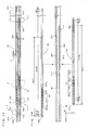
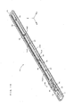
- FIG. 1 is a perspective view showing a first embodiment of an actuator to which the disclosure is applied.
- FIGS. 2A and 2B are sectional views along a line indicated by arrows A-A of FIG. 1 .
- XYZ orthogonal coordinate axes indicating a longitudinal direction of the actuator as an X direction, a width direction of the actuator as a Y direction (orthogonal to the X direction) and a height direction of the actuator as a Z direction (orthogonal to the X and Y directions) are shown as appropriate in FIGS. 1 , 2A and 2B and the following figures.
- an arrow side of each coordinate axis is referred to as a positive side as appropriate and a side opposite to the arrow side of each coordinate axis is referred to as a negative side as appropriate.
- This actuator 1 is a single-axis robot with a single rotary shaft 2 and a moving body 3 which moves according to the rotation of the rotary shaft 2.
- the actuator 1 includes an actuator main body 10 made of, e.g. alloy steel such as stainless steel or metal (light metal) such as aluminum.
- the actuator main body 10 is configured by a base portion having a long plate shape extending in the X direction.
- Each component of the actuator 1 including the rotary shaft 2 and a motor M is mounted on the upper surface of the actuator main body 10.
- This rotary shaft 2 is a feed screw such as a ball screw extending straight in an axial direction parallel to the X direction, and arranged in a center of the upper surface of the actuator main body 10 in the Y direction. Further, bearing members 4U, 4D are fixed on the upper surface of the actuator main body 10 while being spaced apart from each other in the X direction and respectively pivotally support an upstream end part and a downstream end part of the rotary shaft 2 in the X direction. Thus, the rotary shaft 2 is rotatably held in a state spaced apart by a predetermined distance in the height direction Z from the upper surface of the actuator main body 10.
- a rotational drive shaft (not shown) of the motor M is connected to the downstream end part of this rotary shaft 2 in the X direction via a coupling (not shown).
- a rotational drive force generated in the motor M is given to the downstream end part of the rotary shaft 2 in the X direction, i.e. a (+X) direction end part and the rotary shaft 2 rotates about a rotation center line extending in the axial direction X.
- a feed nut 31 is threadably engaged with the rotary shaft 2 and a slider 32 is attached to the feed nut 31.
- the feed nut 31 and the slider 32 integrally move as the moving body 3 along the rotary shaft 2 according to the rotation of the rotary shaft 2.
- a first guide mechanism 5 is provided on the upper surface of the actuator main body 10.
- the moving body 3 is attached to the moving body sliders 531, 532 out of these sliders. More specifically, as shown in FIG. 1 , a (-Y) side end part and a (+Y) side end part of the slider 32 included in the moving body 3 are fixed to the upper surfaces of the moving body sliders 531, 532. Then, the moving body 3 is reciprocally movable by being guided in the X direction by the first guide mechanism 5 while being supported in a state supported at both ends, so to speak, by the first guide mechanism 5.
- supports 61U, 61D are respectively attached to the support sliders 54U, 54D out of the remaining sliders.
- These supports 61U, 61D are components of a resonance suppressing mechanism 6 and respectively located upstream of and downstream of the moving body 3 in the axial direction X.
- These upstream and downstream supports 61 U, 61 D are integrally movable in the X direction in a state held on a unit 62 likewise as a component of the resonance suppressing mechanism 6.
- supports 71U, 71D are respectively attached to the support sliders 55, 55D.
- These supports 71U, 71D are components of a resonance suppressing mechanism 7 and respectively located upstream of and downstream of the moving body 3 in the axial direction X.
- the unit 72 is identical to the unit 62 except that a second pulley supporting portion 721b is shorter than the corresponding one of the unit 62. That is, in the unit 72, a first pulley supporting portion 721 a and the second pulley supporting portion 721b are coupled by a coupling portion 723 to form a long unit main body 721 extending in the X direction. Pulleys 722, 723 are respectively rotatably mounted on the upper surfaces of these pulley supporting portions 721 a, 721b, and a wire 724 is mounted between this pair of pulleys 722, 723. Further, reference signs 721U, 721D, 721M and 721T in FIGS. 3A and 3B respectively indicate an upstream holding part, a downstream holding part, an intermediate part and a tension acting part of the unit main body 721.
- two resin sliders 812 are fitted into the guide groove 822 in a state similar to the resin sliders 811, and slidable in the X direction along the guide groove 822.
- the resin sliders 811, 812 are respectively movable only in the X direction along the guide grooves 821, 822 while being firmly engaged with the guide grooves 821, 822 and restricted from movements in directions other than the X direction.
- the resin sliders 811, 812 slide while being guided by the guide grooves 821, 822 without being detached from the guide grooves 821, 822 even if the lower surface of the actuator main body 10 is mounted on a vertical or ceiling surface, let alone when it is mounted on a horizontal surface.
- the unit main body 621 is attached to the two resin sliders 811 configured in this way. More specifically, as is understood from FIGS. 3A and 3B , the two resin sliders 811 are both connected to the intermediate part 621M of the unit main body 621 and hold the unit main body 621 in such a manner as to be arranged on a straight line with the pair of pulleys 622, 623 when the unit main body 621 is viewed in a direction of rotary shafts of the pulleys 622, 623, i.e. in the Z direction. This can prevent the unit main body 621 from being deformed into an arch shape such as due to gravitational sagging, warping or curvature.
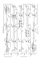
- the units 62, 72 configured as just described move in the (-X) direction together in conjunction with the moving body 3 while the pair of pulleys 722, 723 rotate counterclockwise and the pair of pulleys 622, 623 rotate counterclockwise at a speed slower than the pulleys 722, 723 in the plane of FIG. 7 .
- the moving speed of the unit 62 is 1/3 of the moving speed of the moving body 3 and the moving speed of the unit 72 is 2/3 of the moving speed of the moving body 3 as shown by dotted lines in FIG. 7 .
- the unit main body 621 is movable along the guide rail 82 by being held on the resin sliders 811.
- the unit 62 moves the unit main body 621 in conjunction with the movement of the moving body 3 while holding the support pair (upstream support 61U and downstream support 61D) by the unit main body 621, thereby moving the support pair in the axial direction X.
- the unit 62 (72) is so configured that the distance between the first pulley supporting portion 621 a (721 a) and the second pulley supporting portion 621b (721b) is adjustable, the tension of the wire 624 (724) can be adjusted.
- the unit main body 621 (721) can be satisfactorily moved by applying a proper tension to the wire 624 (724) in the unit 62 (72).
- a function of suppressing the occurrence of resonance can be stably realized.
- the support pair can be stably moved in conjunction with the movement of the moving body 3.
- the unit main body tends to be deformed into an arch shape by being subjected to the tension of the wire.
- the resin sliders 811, 812 are attached at the tension acting part 612T, 721T of the unit main body 621, 721 as shown in FIG 3B , the actuator 1 can be smoothly operated by suppressing the above deformation and ensuring a desired wire tension.
- a (-Y) direction side end part of the moving body 3 is attached to the moving body sliders out of these sliders, and the moving body 3 is reciprocally movable while being supported in a so-called cantilevered state and guided in the X direction by the first guide mechanism 5.
- the supports 61D, 91D, 71D, 71U, 91U and 61U are respectively attached to the support sliders 56D, 57D, 58D, 58U, 57U and 56U out of the remaining sliders.
- the supports 91U, 91D are components of a resonance suppressing mechanism 9, and respectively located upstream and downstream of the moving body 3 in the axial direction X.
- upstream support 91U and downstream support 91D are integrally movable in the X direction in a state held on the unit 92.
- the supports 91U, 91D are configured to be capable of supporting the rotary shaft 2 similarly to the supports 61U, 61D, 71U and 71D and both have the same basic configuration as the supports 61U, 61D, 71U and 71D.
- the unit 92 as another component of the resonance suppressing mechanism 9 is basically identical to the units 62, 72 except in that a length of a unit main body 921 in the X direction is shorter than that of the unit 62 and longer than that of the unit 72.
- the unit 92 includes the long unit main body 921 extending in the X direction, a pair of pulleys 922, 923 ( FIG. 10 ) provided rotatably with respect to the unit main body 921 while being spaced apart from each other in the X direction, and a wire 924 ( FIG 10 ) mounted between the pair of pulleys 922, 923.
- the unit 92 is arranged between the units 62 and 72 in the Y direction and the units 62, 92 and 72 are supported on resin sliders 811 813, 812 of a second guide mechanism 8 in a state arranged in the Y direction. Also in this second embodiment, as shown in FIG. 9 , the second guide mechanism 8 and these units 62, 72 and 92 are provided in a space between the rotary shaft 2 and the actuator main body 10. More specifically, in the second guide mechanism 8, a guide rail 82 extending in the X direction is fixed to the upper surface of the actuator main body 10 below the rotary shaft 2. Three guide grooves 821, 823 and 822 extend in the X direction on this guide rail 82.
- a unit main body 621 is attached to two resin sliders 811.
- This unit main body 621 has a length which is about 3/4 of an external thread formation area of the rotary shaft 2, i.e. a moving stroke of the moving body 3, and the supports 61D, 61U are respectively fixed to the upper surfaces of upstream and downstream end parts in the X direction.
- the unit 62 and the supports 61D, 61U are made integrally movable in the X direction by the resin sliders 811. Further, the unit main body 921 is attached to two resin sliders 813.
- An intermediate part (not shown) of this unit main body 921 is held on the resin sliders 813 and the unit 92 and the supports 91D, 91U are made integrally movable in the X direction by the resin sliders 813. Further, the unit main body 721 is attached to two resin sliders 812.
- a part of the wire 624 is fixed to the actuator main body 10 by a fixing metal fitting 11 at a side upstream of the pair of pulleys 622, 623 in the arrangement direction Y, i.e. at the (-Y) direction side as in the first embodiment.
- a fixing metal fitting 11 at a side upstream of the pair of pulleys 622, 623 in the arrangement direction Y, i.e. at the (-Y) direction side as in the first embodiment.
- the unit 72 located at a most downstream side i.e.
- the units 62, 92 and 72 function as speed reducers in this embodiment.
- the moving body 3 moves, for example, in the (-X) direction, distances among the upstream end part (bearing 4U) of the rotary shaft 2, the supports 61U, 91U and 71U and the moving body 3 become gradually shorter at the side upstream of the moving body 3, whereas distances among the downstream end part (bearing 4D) of the rotary shaft 2, the supports 61 D, 91D and 71D and the moving body 3 gradually become longer at the side downstream of the moving body 3.
- the resonance of the rotary shaft 2 is effectively suppressed by such movements of six supports 61D, 61 U, 92D, 92U, 71D and 71 U.
- a part of the endless string in the most upstream unit, may be coupled to the unit main body of the most downstream unit at a side downstream of the pair of rotating members in the arrangement direction, and in the most downstream unit, a part of the endless string may be coupled to the unit main body of the most upstream unit at a side upstream of the pair of rotating members in the arrangement direction.
- one intermediate unit may be added between the most upstream unit and the most downstream unit in the arrangement direction, in the most upstream unit, a part of the endless string may be coupled to the unit main body of the intermediate unit at a side downstream of the pair of rotating members in the arrangement direction, in the intermediate unit, a part of the endless string may be coupled to the unit main body of the most upstream unit at a side upstream of the pair of rotating members in the arrangement direction and a part of the endless string may be coupled to the unit main body of the most downstream unit at a side downstream of the pair of rotating members in the arrangement direction, and in the most downstream unit, a part of the endless string may be coupled to the unit main body of the intermediate unit at a side upstream of the pair of rotating members in the arrangement direction.
- the number of the supports can be easily increased by a simple structure, and these supports move along the rotary shaft while supporting the rotary shaft, whereby a support span of the rotary shaft becomes shorter.
- the number of revolutions at which the rotary shaft resonates can be increased and the suppression of the resonance of the rotary shaft can be enhanced.
- the unit main body 921 is held on the resin sliders 813 and movable along the guide rail 82.
- the unit 92 moves the unit main body 921 in conjunction with the movement of the moving body 3 while holding the support pair (upstream support 91U and downstream support 91D) by the unit main body 921, thereby moving the support pair in the axial direction X.
- arched deformation such as curvature, warping or gravitational sagging can be effectively prevented also for the unit main body 921 since not only the pair of the supports are held at the upstream holding part and the downstream holding part of the unit main body 921, but also the intermediate part is connected to the resin sliders 813. As a result, the support pair can be stably moved in conjunction with the movement of the moving body 3.
- the actuator 1 can be smoothly operated by suppressing the above deformation and ensuring a desired wire tension.
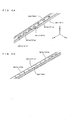
- the fixing metal fitting 11 may include a main body fixing member 111, a wire holding member 112 and compression springs 113.
- a base end part of the main body fixing member 111 is attached to the actuator main body 10. Further, rod-like projections project in the (+X) and (-X) directions in parallel to the wire 624 of the unit 62 on a tip part extending from the base end part of the main body fixing member 111 toward the unit 62.
- the wire holding member 112 two engaging portions extend from a holding portion to hold the wire 624 toward the main body fixing member 111.
- Each engaging portion is provided with a through hole, and the rod-like projection is loosely inserted through each through hole.
- the wire holding member 112 is movable with respect to the main body fixing member 111 by about half the separating distance of the two engaging portions, but further movements thereof in the X direction and movements in the Y direction and Z direction are prevented. Further, an impact force is alleviated by externally fitting the compression springs on the rod-like projections between the tip part of the main body fixing member 111 and the engaging portions of the wire holding member 112 and applying biasing forces in the X direction.
- the resin sliders 811, 812 and 813 correspond to an example of "slide members".
- the slide members are made lighter and loads on the motor M are reduced.
- sliders formed of a material other than the resin material, such as a metal material may be used as the "slide members".
- the unit main bodies are formed to have a substantially inverse U shaped YZ cross-section in terms of making the unit main bodies 621, 721 and 921 lighter and ensuring rigidity.
- the cross-sectional shapes of the unit main bodies are not limited to this.
- the units may be formed into a substantially H shape as shown in FIG. 12A .
- hollow part(s) may be provided in the unit main bodies, for example, as shown in FIGS. 12B to 12D .
- a plurality of pulleys are arranged side by side in the Y direction in such a posture that the rotary shafts are parallel to the Z direction as shown in FIGS. 2 and 9 in the above embodiments
- the arrangement postures and arrangement direction of the pulleys can be appropriately changed.
- a plurality of pulleys may be arranged side by side in the Y direction in such a posture that the rotary shafts are parallel to the Y direction.
- a plurality of pulleys are arranged side by side in the height direction Z in such a posture that the rotary shafts are parallel to the Z direction.
- a plurality of units are layered in the height direction Z.
- two supports are provided on each of the (+Y) direction side and of the (-Y) direction side of the moving body 3, two units are provided and "M" of the disclosure is "2".
- the supports 71U, 71D correspond to a "first support” of the disclosure
- the supports 61U, 61D corresponds to a "second support” of the disclosure.
- the units 62, 72 respectively correspond to examples of a "first speed reducer” and a “second speed reducer” of the disclosure.
- the resonance suppressing mechanisms 7, 6 respectively correspond to a "first device” and a "second device” of the disclosure.
- the supports 71U, 71D correspond to the "first support” of the disclosure
- the supports 91U, 91D corresponds to the "second support” of the disclosure
- the supports 61U, 61D corresponds to a "third support” of the disclosure.
- the units 72, 92 and 62 respectively correspond to examples of the "first speed reducer", the “second speed reducer” and a “third speed reducer” of the disclosure.
- the resonance suppressing mechanisms 7, 9 and 6 respectively correspond to the "first device", the "second device” and a "third device” of the disclosure.
- M is not limited to “2" or “3” described above and may be 4 or more.
- M of the disclosure may be an integer equal to or more than 2 and speed reduction ratios of N/(N+1), (N-1)/(N+1), ..., 1/(N+1) are obtained by successively connecting M units.
- pulleys are used as “rotating members” of the disclosure and the wire is used as an "endless string” of the disclosure in each unit in the above embodiments
- a combination of the "rotating members” and the “endless string” is not limited to this.
- a combination of sprockets and a chain, a combination of pulleys and a belt or the like may be employed.
- the resin sliders 811, 812 are respectively configured to be slidable in the X direction along the guide grooves 821, 822 formed on the guide rail 82 in the above first embodiment
- the configuration of the guide rail 82 is not limited to this.
- a guide rail 83 having a substantially I-shaped YZ cross-section may be, for example, used as shown in FIGS. 13A and 13B (third embodiment).
- each unit main body 621, 721, 921 is held by the two resin sliders in the above embodiments
- the number of the resin sliders is not limited to "2" and is an arbitrary natural number equal to or more than 1.
- the shapes of the resin sliders are not limited to those in the above embodiments and any shape can be employed provided that the resin sliders are slidable along the guide rail.
- only one of the two resin sliders 811 is attached to the tension acting part 621T of the unit main body 621 in the unit 62 and both of the two resin sliders 81 are attached to the tension acting part 721T of the unit main body 721 in the unit 72 as shown in FIGS. 3A and 3B .
- the number of the supports in each resonance suppressing mechanism is arbitrary without being limited to this. Further, the number of the supports may be different in each resonance suppressing mechanism.
- the disclosure is applied to the actuator provided with two resonance suppressing mechanisms in the first embodiment and to the actuator provided with three resonance suppressing mechanisms in the second embodiment, objects to which the disclosure is applied are not limited to these. That is, the disclosure is also applicable to actuators provided with one, four or more resonance suppressing mechanisms.
- a frictional force acts between the rotating rotary shaft and the support since the support is in contact with the rotary shaft.
- the frictional force between the rotary shaft and the support is preferably small. Accordingly, it may be considered to reduce the frictional force between the rotary shaft and the support by reducing the size of the support in an axial direction of the rotary shaft to narrow a part where the rotary shaft and the support are in contact.
- the supports shown in the above embodiments are configured to be able to combine the suppression of loads on the drive source and the suppression of the resonance of the rotary shaft. Accordingly, this point is described in detail next. Note that this technology on the supports can be applied not only to the above actuators to move the supports in conjunction with a movement of the moving body, but also to an actuator (shown in FIGS. 14 to 21 ) configured differently from this. Thus, in the actuator illustrated in the following description, the supports are not necessarily moved in conjunction with a movement of a moving body.
- FIG 14 is a perspective view showing a modification of the actuator.
- FIG. 15 is a plan view of the actuator illustrated in FIG. 14 .
- XYZ orthogonal coordinate axes indicating a longitudinal direction of the actuator as an X direction, a width direction of the actuator as a Y direction (orthogonal to the X direction) and a thickness direction of the actuator as a Z direction (orthogonal to the X and Y directions) are shown as appropriate.
- an arrow side of each coordinate axis is referred to as a positive side as appropriate and a side opposite to the arrow side of each coordinate axis is referred to as a negative side as appropriate.
- This actuator 21 is a single-axis robot with a single rotary shaft 22 and a moving body 3 which moves according to the rotation of the rotary shaft 22.
- the actuator 21 includes a housing 210 made of, e.g. alloy steel such as stainless steel or metal (light metal) such as aluminum.
- the housing 210 is shaped to be long in the X direction and open on opposite sides in the X direction. Further, the opening is also open on a positive side in the Z direction. This enables components of the actuator 21 to be mounted into the housing 210 through the opening in the Z direction, thereby facilitating the assembling of the actuator 21.
- This rotary shaft 22 is a screw extending straight in an axial direction parallel to the X direction, and arranged in a center of the housing 210 in the Y direction.
- the actuator 21 includes two bearing members 24 respectively fixed to opposite end parts of the housing 210 in the X direction, and each end part of the rotary shaft 22 in the X direction is rotatably supported by the bearing member 24.
- the actuator 21 includes a motor M fixed to the end part of the housing 210 on the positive side in the X direction, and the bearing member 24 on the positive side in the X direction couples the motor M and the rotary shaft 22 to each other.
- the rotary shaft 22 can be rotated about a center line thereof by being driven by the motor M.
- the moving body 23 is threadably engaged with the rotary shaft 22 by a nut and moves in the X direction along the rotary shaft 22 according to the rotation of the rotary shaft 22.
- This movement of the moving body 23 is guided by guide rails 25 arranged in parallel to the rotary shaft 22. That is, in the housing 210, the guide rails 25 are respectively fixed at opposite sides of the rotary shaft 22 in the Y direction and the moving body 23 moves in the X direction along the guide rails 25 while being engaged with the guide rails 25 at opposite end parts in the Y direction.
- the actuator 21 includes supports 26 to support the rotary shaft 22 while being engaged with the rotary shaft 22.
- the housing 210 two supports 26 are provided between each of the bearing members 24 on the opposite ends in the X direction and the moving body 23. In this way, two supports 26 are arranged along the rotary shaft 22 at each of the positive and negative sides of the moving body 23 in the X direction.
- Each support 26 is movable along the rotary shaft 22 while supporting the rotary shaft 22, and moves together with the moving body 23 in a state coupled to the moving body 23, for example, at the positive side of the moving body 23 in the X direction in FIGS. 14 and 15 .
- each support 26 has a different movable range. This point is described for the supports provided at the positive side of the moving body 23 in the X direction and those provided at the negative side of the moving body 23 in the X direction.
- the actuator 21 includes two stoppers 27 arranged in the X direction at a negative side of the rotary shaft 22 in the Y direction. These stoppers 27 are arranged to correspond to stop positions Ps(1), Ps(2) to stop the respective supports 26 at the stop positions Ps(1), Ps(2) different from each other in the X direction. Note that the stop position Ps(1) is located on the positive side in the X direction and the stop position Ps(2) is located on the negative side in the X direction.
- the stopper 27 corresponding to the stop position Ps(2) limits the movable range of the support 26 on the negative side in the X direction out of the two supports 26 to the positive side of the stop position Ps(2) in the X direction.
- the support 26 on the negative side in the X direction can move together with the moving body 23 in the movable range (including the stop position Ps(2)) at the positive side of the stop position Ps(2) in the X direction, but is disengaged from the moving body 23 and stops at the stop position Ps(2) if the moving body 23 moves to the negative side in the X direction beyond this movable range.
- each support 26 can stop at the stop position Ps(1), Ps(2) and support the moving body 23 and, on the other hand, can move in the X direction in the movable range on the side of the bearing member 24 from the stop position Ps(1), Ps(2) so as not to hinder a movement of the moving body 23. That is, the support 26 stops at the stop position Ps(1), Ps(2) and supports the rotary shaft 22 while the moving body 23 is moving at a opposite side of the movable range across the stop position Ps(1), Ps(2). On the other hand, while the moving body 23 is in the movable range, the support 26 moves together with the moving body 23 and does not hinder a movement of the moving body 23 in the movable range. In this way, the vibration of the rotary shaft 22 can be suppressed by supporting the rotary shaft 22 by the supports 26 without hindering a movement of the moving body 23.
- the stopper 27 corresponding to the stop position Ps(3) limits the movable range of the support 26 on the negative side in the X direction out of the two supports 26 to the negative side of the stop position Ps(3) in the X direction.
- the support 26 on the negative side in the X direction can move together with the moving body 23 in the movable range (including the stop position Ps(3)) at the negative side of the stop position Ps(3) in the X direction, but is disengaged from the moving body 23 and stops at the stop position Ps(3) if the moving body 23 moves to the positive side in the X direction beyond this movable range.
- the stopper 27 corresponding to the stop position Ps(4) limits the movable range of the support 26 on the positive side in the X direction out of the two supports 26 to the negative side of the stop position Ps(4) in the X direction.
- the support 26 on the positive side in the X direction can move together with the moving body 23 in the movable range (including the stop position Ps(4)) at the negative side of the stop position Ps(4) in the X direction, but is disengaged from the moving body 23 and stops at the stop position Ps(4) if the moving body 23 moves to the positive side in the X direction beyond this movable range.
- each support 26 can stop at the stop position Ps(3), Ps(4) and support the moving body 23 and, on the other hand, can move in the X direction in the movable range on the side of the bearing member 24 from the stop position Ps(3), Ps(4) so as not to hinder a movement of the moving body 23.
- the vibration of the rotary shaft 22 can be suppressed by supporting the rotary shaft 22 by the supports 26 without hindering a movement of the moving body 23.
- the moving body 23 can move along the rotary shaft 22 while being appropriately accompanied by the supports 26.
- the actuator 21 includes stoppers 28 to limit the movable range of such a moving body 23. These stoppers 28 are respectively provided on the opposite end parts of the housing 210 in the X direction and fixed to the housing 210 at inner sides of the bearing members 24. Thus, the moving body 23 moved to the end part in the X direction comes into contact with the stopper 28 to be stopped.
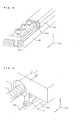
- FIG 16 is a perspective view illustrating the configuration of the support and its periphery.
- FIG. 17 is a plan view illustrating the configuration of the support and its periphery. Note that a member 264 unseen by being hidden behind a member 260 is shown by dashed-dotted line in FIG. 17 .
- FIG. 18 is a partial sectional view illustrating the configuration of the support and its periphery and a ZX cross-section passing through the center line of the rotary shaft 22.
- the support 26 is schematically configured such that a shaft contact portion 262 and a guide engaging portion 264 are attached to a frame 260.
- the frame 260 is made of, e.g. alloy steel such as stainless steel or metal (light metal) such as aluminum and includes a shaft facing portion 2601 surrounding the rotary shaft 22 from the positive side in the Z direction and the opposite sides in the Y direction and a guide facing portion 2602 facing the guide rail 25 from the positive side in Z direction.
- the shaft contact portion 262 is fixed to a negative side of the shaft facing portion 2601 of the frame 260 in the Z direction
- the guide engaging portion 264 is fixed to a negative side of the guide facing portion 2602 of the frame 260.
- the shaft contact portion 262 configured as just described has a length L1 in the X direction along the rotary shaft 22.
- the length L1 can be evaluated as a distance in the X direction between opposite ends of a range where the shaft contact portion 262 is held in contact with the rotary shaft 22 at the contact parts 2624a.
- the length L1 can be evaluated as a distance between positive side ends of the contact parts 2624a in the X direction where the divided bush 2622 on the positive side in the X direction is in contact with the rotary shaft 22 and negative side ends of the contact parts 2624a in the X direction where the divided bush 2622 on the negative side in the X direction is in contact with the rotary shaft 22.
- the guide engaging portion 264 includes an engaging part 264a cut into a groove extending in parallel to the X direction, and is engaged with the guide rail 25 at the engaging part 264a. In this way, the guide engaging portion 264 is movable in the X direction along the guide rail 25 while being engaged with the guide rail 25 at the engaging part 264a.
- the guide engaging portion 264 configured as just described has a length L2 longer than the length L1 in the X direction along the rotary shaft 22 (L2 > L1).
- the length L2 is evaluated as a distance in the X direction between opposite ends of a range where the guide engaging portion 264 is held in contact with the guide rail 25 at the engaging part 264a.
- the length L2 can be evaluated as a distance between opposite ends of the engaging part 264a in the X direction.
- the guide engaging portion 264 includes a projecting part 264b longer than the shaft contact portion 262 in the axial direction (X direction) of the rotary shaft 22 and projecting toward the positive side in the X direction with respect to the shaft contact portion 262.
- the guide facing portion 2602 attached with the guide engaging portion 264 is longer in the X direction than the shaft facing portion 2601 attached with the shaft contact portion 262 and includes a projecting part 2602b projecting toward the positive side in the X direction with respect to the shaft facing portion 2601.
- the guide facing portion 2602 is slightly longer than the guide engaging portion 264 in the X direction.
- the support 26 supports the rotary shaft 22 with the shaft contact portion 262 while being engaged with the guide rail 25 at the guide engaging portion 264.
- the guide engaging portion 264 is movable in the X direction along the guide rail 25, and the shaft contact portion 262 is movable in the X direction along the rotary shaft 22.
- the support 26 is movable in the X direction as a whole.
- the support 26 includes a roller 266, which is rotatable about a center of rotation parallel to the Y direction, on an end part of a positive side of the shaft facing portion 2601 in the Z direction. Such a roller 266 is biased toward the positive side in the Z direction by an elastic member such as a spring and used to engage the support 26 with the moving body 23. Further, the support 26 includes a contact portion 2603 projecting toward a negative side in the Z direction with respect to the shaft facing portion 2601. Such a contact portion 2603 is used to separate the support 26 from the moving body 23 by coming into contact with the stopper 27.
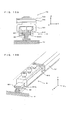
- FIG. 19 is a perspective view illustrating the configuration of the moving body and its periphery.
- FIG. 20 is a partial sectional view illustrating the configuration of the moving body and its periphery and a ZX cross-section passing through the center line of the rotary shaft 22. A state where the moving body 23 is engaged with the two supports 26 on the positive side in the X direction is illustrated in FIGS. 19 and 20 .
- the moving body 23 includes a rectangular table 230 having a flat surface parallel to the X and Y directions and a nut 231 fixed to a lower side of the table 230 in the Z direction and threadably engaged with the rotary shaft 22.
- a ball thread is configured by the rotary shaft 22 and the nut 231.
- the moving body 23 includes hooks 232 detachably engaged with the rollers 266.
- the hooks 232 are provided at opposite sides of the table 230 in the X direction, and located above the rotary shaft 22 in the Z direction while projecting in the X direction with respect to the table 230.
- the table 230, the nut 231 and the hooks 232 included in the moving body 23 are made of, e.g. alloy steel such as stainless steel or metal (light metal) such as aluminum.
- Steps 5 to 1 are performed in this order in the case of moving the moving body 23 from the end part on the negative side in the X direction to the end part on the positive side in the X direction.
- the moving body 23 most distant from this bearing member 24 and the supports 26 between this bearing member 24 and the moving body 23 satisfy conditions similar to those of the aforementioned intervals C1, C2 and C3 in the state shown in Step 5.
- any of the intervals C4, C5 and C6 is set shorter than half the wavelength of basic vibration of the rotary shaft 22 that resonates with the rotation of the rotary shaft 22 at the maximum number of revolutions and noise and the breakage of the rotary shaft 22 can be suppressed by suppressing the vibration of the rotary shaft 22 by the bearing member 24, the supports 26 and the moving body 23.
- a mutual relationship of the intervals C4, C5 and C6 is also set. Specifically, the intervals C5 and C6 are set longer than the interval C4. Note that it does not matter whether or not the intervals C5, C6 are equal to each other or one is longer than the other. From such a state, the moving body 23 is moved toward the negative side in the X direction while Steps 4 to 1 are successively performed.
- the support 26 includes the guide engaging portion 264 to be engaged with the guide rail 25 (guide member) and the shaft contact portion 262 to support the rotary shaft 22 by being held in contact with the rotary shaft 22, and the guide engaging portion 264 is longer than the shaft contact portion 262 (L2 > L1) in the X direction (axial direction). That is, the support 26 is engaged with the guide rail 25 at the relatively wide guide engaging portion 264 while being held in contact with the rotary shaft 22 at the relatively narrow shaft contact portion 262.
- a frictional force between the rotary shaft 22 and the support 26 can be reduced by holding the support 26 in contact with the rotary shaft 22 at the narrow shaft contact portion 262 and the support 26 can be stably supported by firmly engaging the support 26 with the guide rail 25 at the wide guide engaging portion 264.
- the resonance of the rotary shaft 22 can be effectively suppressed by stably supporting the supports 26 while loads on the motor M (drive source) are suppressed by reducing frictional forces between the rotary shaft 22 and the supports 26.
- a plurality of (two) supports 26 arranged in the X direction between the moving body 23 and the bearing member 24 are provided in the above actuator 21.
- a frictional force is generated between each of the plurality of supports 26 and the rotary shaft 22.
- it is required to suppress loads on the motor M by reducing a frictional force for the individual support 26.
- it is required not only to reduce the frictional forces, but also to effectively suppress the resonance of the rotary shaft 22 by stably supporting the supports 26. Accordingly, the configuration illustrated here is quite preferable.
- the projecting part 2602b of the guide engaging portion 264 of one support 26 overlaps the shaft contact portion 262 of the other support 26 in the X direction and the projecting part 2602b of the guide engaging portion 264 of the other support 26 overlaps the shaft contact portion 262 of the one support 26 in the X direction. That is, the two adjacent supports 26 can be overlapped in the X direction. Thus, these supports 26 can be fitted into a compact in the X direction and a stroke of the moving body 23 can be extended.
- the interval C2,C5 along the rotary shaft 22 between the supports 26 adjacent in the X direction is longer than the interval C1, C4 along the rotary shaft 22 between the support 26 at the stop position Ps(1), Ps(3) and the bearing member 24 adjacent in the X direction. That is, in the above configuration that the rotary shaft 22 is supported by the plurality of (two) supports 26, the rotary shaft 22 is substantially rigidly supported by the bearing member 24 and the support 26 adjacent to the bearing member 24. Thus, the rotary shaft 22 is firmly supported by such rigid support at a side of this support 26 opposite to the bearing member 24.
- the interval C2, C5 along the rotary shaft 22 between the supports 26 adjacent in the X direction is specified to be longer than the interval C1, C4 along the rotary shaft 22 between the support 26 at the stop position and the bearing member 24 adjacent in the X direction, the resonance of the rotary shaft 2 can be suppressed.
- the interval between the supports 26 stopped at the stop positions can be made wider. For example, such a design of extending the stroke of the moving body 23 while suppressing the number of the supports 26 is facilitated.
- the moving body 23 includes the hooks 232 (engaging portion) detachably engaged with the roller 266 (engaged portion) of the support 26.
- the moving body 23 moves together with the support 26 engaged with the hook 23 after the support 26 stopped at the stop position is engaged with the hook 23.
- the moving body 23 moves while leaving the support 26 stopped at the stop position by the stopper 27 (stop mechanism) and disengaged from the hook 232.
- an operation of moving the support 26 together with the moving body 23 and an operation of disengaging the support 26 from the moving body 23 and stopping the support 26 at the stop position can be easily performed by engaging or disengaging the hook 232 of the moving body 23 and the roller 266 of the support 26.
- the roller 266 is biased toward the hook 232 by the elastic force in a state where the hook 232 of the moving body 23 and the roller 266 of the support 26 are in contact.
- the roller 266 in engaging or disengaging the hook 232 of the moving body 23 and the roller 266 of the support 26, the roller 266 is elastically displaced according to a stress acting between the hook 232 and the roller 266 (specifically, the roller 266 is elastically displaced according to a stress received from a projection projecting toward the negative side in the Z direction on the tip of the hook 232).
- the hook 232 of the moving body 23 and the roller 266 of the support 26 can be smoothly engaged or disengaged.
- the support 26 is engaged with the hook 232 of the moving body 23 via the rotatable roller 266.
- the roller 266 rotates according to a stress acting between the hook 232 and the roller 266.
- the hook 232 of the moving body 23 and the roller 266 of the support 26 can be smoothly engaged or disengaged.
- the stopper 28 (movement restricter) is provided which stops the moving body 23 approaching the bearing member 24 in the state where the clearance ⁇ is formed between the support 26 engaged with the moving body 23 and the bearing member 24.
- the support 26 provided between the moving body 23 and the bearing member 24 collides with the bearing member 24 according to the movement of the moving body 23.
- the strength of the shaft contact portion 262 is, for example, not high since the shaft contact portion 262 of the support 26 is formed to be narrow, the breakage of the shaft contact portion 262 due to the collision of the bearing member 24 can be suppressed.
- both the movement of the moving body 23 and those of the supports 26 are guided by the common guide rails 25.
- the specific configuration of the support 26 can also be variously modified.
- the projecting part 264b of the guide engaging portion 264 projects only toward one side in the X direction with respect to the shaft contact portion 262.
- the projecting part 264b of the guide engaging portion 264 may project toward opposite sides in the X direction with respect to the shaft contact portion 262, so that the support 26 is T-shaped.
- the shaft contact portion 262 and the guide engaging portion 264 are attached to each other via the frame 260 in the above description.
- the shaft contact portion 262 and the guide engaging portion 264 may be attached, for example, by screwing without via the frame 260 or may be integrally formed.
- the specific configurations of the shaft contact portion 262 and the guide engaging portion 264 are also not limited to the above configurations.
- the shaft contact portion 262 may include one, three or more divided bushes 2622 or may include parts other than the divided bushes 2622.
- the roller 266 is biased toward the hook 232 in the state where the hook 232 of the moving body 23 and the roller 266 of the support 26 are in contact by elastic force.
- the hook 232 may be biased toward the roller 266 by an elastic force.
- the configuration to couple the moving body 23 and the support 26 is not limited to the aforementioned one by the hook 232 and the roller 266.
- the moving body 23 and the support 26 may be attracted, for example, by a magnetic force or the like.
- interval C1 may not be shorter than the interval C2 or C3 and the interval C4 may not be shorter than the interval C5 or C6.
- the number of the supports 26 provided between the bearing member 24 and the moving body 23 is not limited to two and one, three or more supports 26 may be provided.
- the actuator shown in FIGS. 14 to 21 comprises: a rotary shaft extending in an axial direction; a drive source to rotate the rotary shaft; a moving body attached to the rotary shaft and movable in the axial direction according to the rotation of the rotary shaft; a bearing member to bear the rotary shaft; a guide member provided along the rotary shaft and extending in the axial direction; and a support movable along the guide member while being engaged with the guide member and configured to support the rotary shaft between the moving body and the bearing member, wherein the support includes a guide engaging portion to be engaged with the guide member and a shaft contact portion configured to support the rotary shaft in contact with the rotary shaft, and the guide engaging portion is longer than the shaft contact portion in the axial direction.
- the support includes the guide engaging portion to be engaged with the guide member and the shaft contact portion configured to support the rotary shaft in contact with the rotary shaft, and the guide engaging portion is longer than the shaft contact portion in the axial direction. That is, the support is engaged with the guide member at the relatively wide guide engaging portion while being held in contact with the rotary shaft at the relatively narrow shaft contact portion.
- a frictional force between the rotary shaft and the support can be reduced by holding the support in contact with the rotary shaft at the narrow shaft contact portion and the support can be stably supported by firmly engaging the support with the guide member at the wide guide engaging portion.
- the resonance of the rotary shaft can be effectively suppressed by stably supporting the support while a load on the drive source is suppressed by reducing a frictional force between the rotary shaft and the support.
- the actuator may be so configured as to include a plurality of supports arranged in the axial direction between the moving body and the bearing member.
- a frictional force is created between each of the plurality of supports and the rotary shaft.
- it is required to suppress loads on the drive source by reducing a frictional force for the individual support.
- it is required not only to reduce the frictional forces, but also to effectively suppress the resonance of the rotary shaft by stably supporting the supports. Accordingly, the configuration illustrated here is quite preferable.
- the actuator may be so configured that the guide member is provided at each of the opposite sides of the rotary shaft in a width direction orthogonal to the axial direction and two supports adjacent along the rotary shaft are engaged with the mutually different guide members at the guide engaging portions thereof.
- the actuator may be so configured that the guide engaging portion of one of the two supports includes a projecting part projecting toward the other support with respect to the shaft contact portion, and the guide engaging portion of the other support includes a projecting part projecting toward the one support with respect to the shaft contact portion, the projecting part of the guide engaging portion of the one support is separated from the other support in the width direction, the projecting part of the guide engaging portion of the other support is separated from the one support in the width direction, and the projecting part of the guide engaging portion of the one support overlaps with the shaft contact portion of the other support in the axial direction and the projecting part of the guide engaging portion of the other support overlaps with the shaft contact portion of the one support in the axial direction when the two supports approach each other.
- the actuator may be so configured that stop mechanism is further provided to stop each of the plurality of supports at mutually different positions, each of the supports is movable in the axial direction in a movable range from the stop position to the bearing member, is stopped at the stop position by the stop mechanism while the moving body is moving at an opposite side of the movable range across the stop position and moves in the movable range together with the moving body while the moving body is in the movable range.
- the support can stop at the stop position and support the rotary shaft and, on the other hand, can move in the axial direction in the movable range from the stop position to the bearing member so as not to hinder a movement of the moving body. That is, while the moving body is moving at an opposite side of the movable range across the stop position, the support is stopped at the stop position and supports the rotary shaft. On the other hand, while the moving body is in the movable range, the support moves together with the moving body so as not to hinder the movement of the moving body. In this way, it is possible to support the rotary shaft by the supports and suppress the vibration of the rotary shaft without hindering the movement of the moving body.
- the resonance of the rotary shaft can be effectively suppressed by stably supporting the supports while loads on the drive source are suppressed by reducing frictional forces between the rotary shaft and the supports.
- the actuator may be so configured that the stop mechanism specifies an interval along the rotary shaft between the supports adjacent in the axial direction to be longer than an interval along the rotary shaft between the support at the stop position and the bearing member adjacent in the axial direction. That is, in the above configuration that the rotary shaft is supported by the plurality of supports, the rotary shaft is substantially rigidly supported by the bearing member and the support adjacent in the axial direction. Thus, the rotary shaft is firmly supported by such rigid support at a side of this support opposite to the bearing member.
- the interval along the rotary shaft between the supports adjacent in the axial direction is specified to be longer than the interval along the rotary shaft between the support at the stop position and the bearing member adjacent in the axial direction, the resonance of the rotary shaft can be suppressed.
- the interval between the supports stopped at the stop positions can be made wider. For example, such a design of extending the stroke of the moving body while suppressing the number of the supports is facilitated.
- an operation of moving the support together with the moving body in the movable range and an operation of disengaging the support from the moving body and stopping the support at the stop position can be easily performed by engaging or disengaging the engaging portion of the moving body and the engaged portion of the support.
- the actuator may be so configured that at least one of the engaging portion of the moving body and the engaged portion of the support is biased toward the other by an elastic force.
- at least one of these in engaging or disengaging the engaging portion of the moving body and the engaged portion of the support, at least one of these is elastically displaced according to a stress acting between the engaging portion and the engaged portion.
- the engaging portion of the moving body and the engaged portion of the support can be smoothly engaged or disengaged.
- the actuator may be so configured that the engaged portion is a rotatable roller.
- the engaged portion in engaging or disengaging the engaging portion of the moving body and the engaged portion of the support, the engaged portion (roller) rotates according to a stress acting between the engaging portion and the engaged portion.
- the engaging portion of the moving body and the engaged portion of the support can be smoothly engaged or disengaged.
- the actuator may be so configured that a movement restricter is further provided to stop the moving body approaching the bearing member in a state where a clearance is formed between the bearing member and the support between the moving body and the bearing member.
- a movement restricter is further provided to stop the moving body approaching the bearing member in a state where a clearance is formed between the bearing member and the support between the moving body and the bearing member.
- the actuator may be so configured that the interlocking unit specifies the interval along the rotary shaft between the supports adjacent in the axial direction to be longer than the interval along the rotary shaft between the support and the bearing member adjacent in the axial direction. That is, in the above configuration that the rotary shaft is supported by the plurality of supports, the rotary shaft is substantially rigidly supported by the bearing member and the support adjacent in the axial direction. Thus, the rotary shaft is firmly supported by such rigid support at a side of this support opposite to the bearing member. Thus, even if the interval along the rotary shaft between the supports adjacent in the axial direction is specified to be longer than the interval along the rotary shaft between the support and the bearing member adjacent in the axial direction, the resonance of the rotary shaft can be suppressed. Particularly, by specifying the intervals in this way, the interval between the supports can be made wider. For example, such a design of extending the stroke of the moving body while suppressing the number of the supports is facilitated.
- This disclosure is applicable to actuators in general to move a moving body in an axial direction along a rotary shaft extending in the axial direction by the rotation of the rotary shaft upon receiving a rotational drive force.
Landscapes
- Engineering & Computer Science (AREA)
- General Engineering & Computer Science (AREA)
- Mechanical Engineering (AREA)
- Transmission Devices (AREA)
Applications Claiming Priority (3)
| Application Number | Priority Date | Filing Date | Title |
|---|---|---|---|
| JP2013228542A JP2015086998A (ja) | 2013-11-01 | 2013-11-01 | アクチュエーター |
| JP2014027127A JP6179950B2 (ja) | 2014-02-17 | 2014-02-17 | アクチュエータ |
| JP2014027126A JP6246612B2 (ja) | 2014-02-17 | 2014-02-17 | アクチュエータ |
Publications (3)
| Publication Number | Publication Date |
|---|---|
| EP2881621A2 true EP2881621A2 (fr) | 2015-06-10 |
| EP2881621A3 EP2881621A3 (fr) | 2016-09-14 |
| EP2881621B1 EP2881621B1 (fr) | 2019-12-04 |
Family
ID=51951530
Family Applications (1)
| Application Number | Title | Priority Date | Filing Date |
|---|---|---|---|
| EP14003679.9A Active EP2881621B1 (fr) | 2013-11-01 | 2014-10-30 | Actionneur |
Country Status (4)
| Country | Link |
|---|---|
| US (1) | US9752664B2 (fr) |
| EP (1) | EP2881621B1 (fr) |
| CN (1) | CN104613150B (fr) |
| TW (1) | TWI598525B (fr) |
Cited By (1)
| Publication number | Priority date | Publication date | Assignee | Title |
|---|---|---|---|---|
| TWI632312B (zh) * | 2016-06-29 | 2018-08-11 | 上銀科技股份有限公司 | 具有支撐裝置的滾珠螺桿 |
Families Citing this family (5)
| Publication number | Priority date | Publication date | Assignee | Title |
|---|---|---|---|---|
| CN104444351B (zh) * | 2014-11-07 | 2016-11-02 | 京东方科技集团股份有限公司 | 机械手臂及基板拾取装置 |
| CN204711589U (zh) * | 2015-04-30 | 2015-10-21 | 富泰华工业(深圳)有限公司 | 运动平台 |
| JP6589686B2 (ja) * | 2016-02-24 | 2019-10-16 | 日立オートモティブシステムズ株式会社 | 内燃機関用リンク機構のアクチュエータ |
| TWI615236B (zh) * | 2016-12-13 | 2018-02-21 | Hiwin Tech Corp | 具有模組化支撐裝置之線性傳動機構 |
| US11255416B2 (en) | 2017-09-08 | 2022-02-22 | Liftwave, Inc. | High reduction belt-driven linear actuator |
Citations (1)
| Publication number | Priority date | Publication date | Assignee | Title |
|---|---|---|---|---|
| JP3221804B2 (ja) | 1994-09-28 | 2001-10-22 | 先生精機株式会社 | アクチュエータ |
Family Cites Families (12)
| Publication number | Priority date | Publication date | Assignee | Title |
|---|---|---|---|---|
| JPS6326594Y2 (fr) | 1981-03-16 | 1988-07-19 | ||
| JP2867386B2 (ja) * | 1988-08-31 | 1999-03-08 | 日本精工株式会社 | 送りねじ支持装置 |
| JPH0751962A (ja) | 1993-08-06 | 1995-02-28 | Souzouan:Kk | 回転運動機構 |
| JP3729420B2 (ja) | 1993-10-12 | 2005-12-21 | Smc株式会社 | アクチュエータ |
| GB9415648D0 (en) | 1994-08-03 | 1994-09-21 | Rotork Controls | Differential drive linear actuator |
| DE29724669U1 (de) * | 1996-09-06 | 2003-02-06 | Rexroth Star GmbH, 97424 Schweinfurt | Linearführungseinrichtung |
| DE19636272A1 (de) * | 1996-09-06 | 1998-03-12 | Star Gmbh | Linearführungseinrichtung |
| JPH1119835A (ja) * | 1997-07-03 | 1999-01-26 | Mitsubishi Electric Corp | Xyテーブル |
| WO2001039923A2 (fr) * | 1999-11-30 | 2001-06-07 | HüLLER HILLE GMBH | Machine-outil, notamment machine-outil a plateau long |
| DE10002849C2 (de) | 2000-01-24 | 2002-03-28 | Rexroth Star Gmbh | Lineareinheit |
| JP5547563B2 (ja) | 2010-06-25 | 2014-07-16 | Ntn株式会社 | 電動アクチュエータ |
| WO2012046387A1 (fr) * | 2010-10-08 | 2012-04-12 | 平田機工株式会社 | Dispositif de curseur |
-
2014
- 2014-10-15 TW TW103135724A patent/TWI598525B/zh active
- 2014-10-30 EP EP14003679.9A patent/EP2881621B1/fr active Active
- 2014-10-31 US US14/530,057 patent/US9752664B2/en active Active
- 2014-10-31 CN CN201410602632.5A patent/CN104613150B/zh active Active
Patent Citations (1)
| Publication number | Priority date | Publication date | Assignee | Title |
|---|---|---|---|---|
| JP3221804B2 (ja) | 1994-09-28 | 2001-10-22 | 先生精機株式会社 | アクチュエータ |
Cited By (1)
| Publication number | Priority date | Publication date | Assignee | Title |
|---|---|---|---|---|
| TWI632312B (zh) * | 2016-06-29 | 2018-08-11 | 上銀科技股份有限公司 | 具有支撐裝置的滾珠螺桿 |
Also Published As
| Publication number | Publication date |
|---|---|
| US20150122062A1 (en) | 2015-05-07 |
| CN104613150B (zh) | 2017-09-22 |
| US9752664B2 (en) | 2017-09-05 |
| TW201527664A (zh) | 2015-07-16 |
| EP2881621A3 (fr) | 2016-09-14 |
| CN104613150A (zh) | 2015-05-13 |
| TWI598525B (zh) | 2017-09-11 |
| EP2881621B1 (fr) | 2019-12-04 |
Similar Documents
| Publication | Publication Date | Title |
|---|---|---|
| EP2881621B1 (fr) | Actionneur | |
| US10301123B2 (en) | Transfer device | |
| EP2924212B1 (fr) | Dispositif d'ouverture et de fermeture de porte coulissante | |
| WO2008094212A3 (fr) | Robot entraîné par courroie ayant un mouvement d'axe z étendu | |
| US8833190B2 (en) | Relative-rotation synchronous movement-aid device | |
| CN111278763B (zh) | 推力升降装置 | |
| JP2012218897A (ja) | エレベータ | |
| US8613550B2 (en) | Slide cover stabilization and synchronization mechanism | |
| JP6246612B2 (ja) | アクチュエータ | |
| US8978495B2 (en) | Synchronous movement-aid device for slide module | |
| JP6179950B2 (ja) | アクチュエータ | |
| CN103261060B (zh) | 运输机截面支承元件、改进工具箱和辊式运输机 | |
| WO2008023435A1 (fr) | Dispositif de porte pour ascenseur | |
| JP6334015B1 (ja) | 線形伝動装置 | |
| US8931360B2 (en) | Linkage-type synchronization module structure | |
| JP2015111989A (ja) | アクチュエーター | |
| JP5406125B2 (ja) | 可動ホーム柵 | |
| US20120291356A1 (en) | Synchronous drive device for slide cover mechanism | |
| CN109138671B (zh) | 一种家具铰链的底座简易结构 | |
| JP6231330B2 (ja) | 制振装置 | |
| WO2021109295A1 (fr) | Paire de rails de guidage linéaire et mécanisme de rail de guidage | |
| HK1194449A1 (zh) | 吊门装置和具有该吊门装置的门装置 | |
| HK1194449B (en) | Door suspension device and door apparatus comprising same | |
| DE602007010198D1 (de) | Sicherheitsvorrichtung für ein sektionales Schliesselement, z.B. Tür, Haupttür, Tor oder dergleichen | |
| JP2008164076A (ja) | 直線移動装置 |
Legal Events
| Date | Code | Title | Description |
|---|---|---|---|
| PUAI | Public reference made under article 153(3) epc to a published international application that has entered the european phase |
Free format text: ORIGINAL CODE: 0009012 |
|
| 17P | Request for examination filed |
Effective date: 20141113 |
|
| AK | Designated contracting states |
Kind code of ref document: A2 Designated state(s): AL AT BE BG CH CY CZ DE DK EE ES FI FR GB GR HR HU IE IS IT LI LT LU LV MC MK MT NL NO PL PT RO RS SE SI SK SM TR |
|
| AX | Request for extension of the european patent |
Extension state: BA ME |
|
| PUAL | Search report despatched |
Free format text: ORIGINAL CODE: 0009013 |
|
| AK | Designated contracting states |
Kind code of ref document: A3 Designated state(s): AL AT BE BG CH CY CZ DE DK EE ES FI FR GB GR HR HU IE IS IT LI LT LU LV MC MK MT NL NO PL PT RO RS SE SI SK SM TR |
|
| AX | Request for extension of the european patent |
Extension state: BA ME |
|
| RIC1 | Information provided on ipc code assigned before grant |
Ipc: F16H 25/24 20060101AFI20160808BHEP |
|
| RBV | Designated contracting states (corrected) |
Designated state(s): AL AT BE BG CH CY CZ DE DK EE ES FI FR GB GR HR HU IE IS IT LI LT LU LV MC MK MT NL NO PL PT RO RS SE SI SK SM TR |
|
| GRAP | Despatch of communication of intention to grant a patent |
Free format text: ORIGINAL CODE: EPIDOSNIGR1 |
|
| STAA | Information on the status of an ep patent application or granted ep patent |
Free format text: STATUS: GRANT OF PATENT IS INTENDED |
|
| INTG | Intention to grant announced |
Effective date: 20190612 |
|
| RAP1 | Party data changed (applicant data changed or rights of an application transferred) |
Owner name: YAMAHA HATSUDOKI KABUSHIKI KAISHA |
|
| RIN1 | Information on inventor provided before grant (corrected) |
Inventor name: KAWATA, KOUJI Inventor name: KAWAUCHI, MOTONORI Inventor name: EGASHIRA, KENJI |
|
| GRAS | Grant fee paid |
Free format text: ORIGINAL CODE: EPIDOSNIGR3 |
|
| GRAA | (expected) grant |
Free format text: ORIGINAL CODE: 0009210 |
|
| STAA | Information on the status of an ep patent application or granted ep patent |
Free format text: STATUS: THE PATENT HAS BEEN GRANTED |
|
| AK | Designated contracting states |
Kind code of ref document: B1 Designated state(s): AL AT BE BG CH CY CZ DE DK EE ES FI FR GB GR HR HU IE IS IT LI LT LU LV MC MK MT NL NO PL PT RO RS SE SI SK SM TR |
|
| REG | Reference to a national code |
Ref country code: GB Ref legal event code: FG4D |
|
| REG | Reference to a national code |
Ref country code: CH Ref legal event code: EP |
|
| REG | Reference to a national code |
Ref country code: AT Ref legal event code: REF Ref document number: 1209815 Country of ref document: AT Kind code of ref document: T Effective date: 20191215 |
|
| REG | Reference to a national code |
Ref country code: DE Ref legal event code: R096 Ref document number: 602014057689 Country of ref document: DE |
|
| REG | Reference to a national code |
Ref country code: IE Ref legal event code: FG4D |
|
| REG | Reference to a national code |
Ref country code: NL Ref legal event code: MP Effective date: 20191204 |
|
| REG | Reference to a national code |
Ref country code: LT Ref legal event code: MG4D |
|
| PG25 | Lapsed in a contracting state [announced via postgrant information from national office to epo] |
Ref country code: SE Free format text: LAPSE BECAUSE OF FAILURE TO SUBMIT A TRANSLATION OF THE DESCRIPTION OR TO PAY THE FEE WITHIN THE PRESCRIBED TIME-LIMIT Effective date: 20191204 Ref country code: LV Free format text: LAPSE BECAUSE OF FAILURE TO SUBMIT A TRANSLATION OF THE DESCRIPTION OR TO PAY THE FEE WITHIN THE PRESCRIBED TIME-LIMIT Effective date: 20191204 Ref country code: BG Free format text: LAPSE BECAUSE OF FAILURE TO SUBMIT A TRANSLATION OF THE DESCRIPTION OR TO PAY THE FEE WITHIN THE PRESCRIBED TIME-LIMIT Effective date: 20200304 Ref country code: FI Free format text: LAPSE BECAUSE OF FAILURE TO SUBMIT A TRANSLATION OF THE DESCRIPTION OR TO PAY THE FEE WITHIN THE PRESCRIBED TIME-LIMIT Effective date: 20191204 Ref country code: GR Free format text: LAPSE BECAUSE OF FAILURE TO SUBMIT A TRANSLATION OF THE DESCRIPTION OR TO PAY THE FEE WITHIN THE PRESCRIBED TIME-LIMIT Effective date: 20200305 Ref country code: NO Free format text: LAPSE BECAUSE OF FAILURE TO SUBMIT A TRANSLATION OF THE DESCRIPTION OR TO PAY THE FEE WITHIN THE PRESCRIBED TIME-LIMIT Effective date: 20200304 Ref country code: ES Free format text: LAPSE BECAUSE OF FAILURE TO SUBMIT A TRANSLATION OF THE DESCRIPTION OR TO PAY THE FEE WITHIN THE PRESCRIBED TIME-LIMIT Effective date: 20191204 Ref country code: LT Free format text: LAPSE BECAUSE OF FAILURE TO SUBMIT A TRANSLATION OF THE DESCRIPTION OR TO PAY THE FEE WITHIN THE PRESCRIBED TIME-LIMIT Effective date: 20191204 |
|
| PG25 | Lapsed in a contracting state [announced via postgrant information from national office to epo] |
Ref country code: RS Free format text: LAPSE BECAUSE OF FAILURE TO SUBMIT A TRANSLATION OF THE DESCRIPTION OR TO PAY THE FEE WITHIN THE PRESCRIBED TIME-LIMIT Effective date: 20191204 Ref country code: HR Free format text: LAPSE BECAUSE OF FAILURE TO SUBMIT A TRANSLATION OF THE DESCRIPTION OR TO PAY THE FEE WITHIN THE PRESCRIBED TIME-LIMIT Effective date: 20191204 |
|
| PG25 | Lapsed in a contracting state [announced via postgrant information from national office to epo] |
Ref country code: AL Free format text: LAPSE BECAUSE OF FAILURE TO SUBMIT A TRANSLATION OF THE DESCRIPTION OR TO PAY THE FEE WITHIN THE PRESCRIBED TIME-LIMIT Effective date: 20191204 |
|
| PG25 | Lapsed in a contracting state [announced via postgrant information from national office to epo] |
Ref country code: PT Free format text: LAPSE BECAUSE OF FAILURE TO SUBMIT A TRANSLATION OF THE DESCRIPTION OR TO PAY THE FEE WITHIN THE PRESCRIBED TIME-LIMIT Effective date: 20200429 Ref country code: RO Free format text: LAPSE BECAUSE OF FAILURE TO SUBMIT A TRANSLATION OF THE DESCRIPTION OR TO PAY THE FEE WITHIN THE PRESCRIBED TIME-LIMIT Effective date: 20191204 Ref country code: NL Free format text: LAPSE BECAUSE OF FAILURE TO SUBMIT A TRANSLATION OF THE DESCRIPTION OR TO PAY THE FEE WITHIN THE PRESCRIBED TIME-LIMIT Effective date: 20191204 Ref country code: CZ Free format text: LAPSE BECAUSE OF FAILURE TO SUBMIT A TRANSLATION OF THE DESCRIPTION OR TO PAY THE FEE WITHIN THE PRESCRIBED TIME-LIMIT Effective date: 20191204 Ref country code: EE Free format text: LAPSE BECAUSE OF FAILURE TO SUBMIT A TRANSLATION OF THE DESCRIPTION OR TO PAY THE FEE WITHIN THE PRESCRIBED TIME-LIMIT Effective date: 20191204 |
|
| PG25 | Lapsed in a contracting state [announced via postgrant information from national office to epo] |
Ref country code: IS Free format text: LAPSE BECAUSE OF FAILURE TO SUBMIT A TRANSLATION OF THE DESCRIPTION OR TO PAY THE FEE WITHIN THE PRESCRIBED TIME-LIMIT Effective date: 20200404 Ref country code: SK Free format text: LAPSE BECAUSE OF FAILURE TO SUBMIT A TRANSLATION OF THE DESCRIPTION OR TO PAY THE FEE WITHIN THE PRESCRIBED TIME-LIMIT Effective date: 20191204 Ref country code: SM Free format text: LAPSE BECAUSE OF FAILURE TO SUBMIT A TRANSLATION OF THE DESCRIPTION OR TO PAY THE FEE WITHIN THE PRESCRIBED TIME-LIMIT Effective date: 20191204 |
|
| REG | Reference to a national code |
Ref country code: DE Ref legal event code: R097 Ref document number: 602014057689 Country of ref document: DE |
|
| REG | Reference to a national code |
Ref country code: AT Ref legal event code: MK05 Ref document number: 1209815 Country of ref document: AT Kind code of ref document: T Effective date: 20191204 |
|
| PLBE | No opposition filed within time limit |
Free format text: ORIGINAL CODE: 0009261 |
|
| STAA | Information on the status of an ep patent application or granted ep patent |
Free format text: STATUS: NO OPPOSITION FILED WITHIN TIME LIMIT |
|
| PG25 | Lapsed in a contracting state [announced via postgrant information from national office to epo] |
Ref country code: DK Free format text: LAPSE BECAUSE OF FAILURE TO SUBMIT A TRANSLATION OF THE DESCRIPTION OR TO PAY THE FEE WITHIN THE PRESCRIBED TIME-LIMIT Effective date: 20191204 |
|
| 26N | No opposition filed |
Effective date: 20200907 |
|
| PG25 | Lapsed in a contracting state [announced via postgrant information from national office to epo] |
Ref country code: SI Free format text: LAPSE BECAUSE OF FAILURE TO SUBMIT A TRANSLATION OF THE DESCRIPTION OR TO PAY THE FEE WITHIN THE PRESCRIBED TIME-LIMIT Effective date: 20191204 Ref country code: AT Free format text: LAPSE BECAUSE OF FAILURE TO SUBMIT A TRANSLATION OF THE DESCRIPTION OR TO PAY THE FEE WITHIN THE PRESCRIBED TIME-LIMIT Effective date: 20191204 Ref country code: PL Free format text: LAPSE BECAUSE OF FAILURE TO SUBMIT A TRANSLATION OF THE DESCRIPTION OR TO PAY THE FEE WITHIN THE PRESCRIBED TIME-LIMIT Effective date: 20191204 |
|
| PG25 | Lapsed in a contracting state [announced via postgrant information from national office to epo] |
Ref country code: IT Free format text: LAPSE BECAUSE OF FAILURE TO SUBMIT A TRANSLATION OF THE DESCRIPTION OR TO PAY THE FEE WITHIN THE PRESCRIBED TIME-LIMIT Effective date: 20191204 |
|
| REG | Reference to a national code |
Ref country code: CH Ref legal event code: PL |
|
| GBPC | Gb: european patent ceased through non-payment of renewal fee |
Effective date: 20201030 |
|
| PG25 | Lapsed in a contracting state [announced via postgrant information from national office to epo] |
Ref country code: LU Free format text: LAPSE BECAUSE OF NON-PAYMENT OF DUE FEES Effective date: 20201030 Ref country code: MC Free format text: LAPSE BECAUSE OF FAILURE TO SUBMIT A TRANSLATION OF THE DESCRIPTION OR TO PAY THE FEE WITHIN THE PRESCRIBED TIME-LIMIT Effective date: 20191204 |
|
| REG | Reference to a national code |
Ref country code: BE Ref legal event code: MM Effective date: 20201031 |
|
| PG25 | Lapsed in a contracting state [announced via postgrant information from national office to epo] |
Ref country code: FR Free format text: LAPSE BECAUSE OF NON-PAYMENT OF DUE FEES Effective date: 20201031 |
|
| PG25 | Lapsed in a contracting state [announced via postgrant information from national office to epo] |
Ref country code: GB Free format text: LAPSE BECAUSE OF NON-PAYMENT OF DUE FEES Effective date: 20201030 Ref country code: LI Free format text: LAPSE BECAUSE OF NON-PAYMENT OF DUE FEES Effective date: 20201031 Ref country code: CH Free format text: LAPSE BECAUSE OF NON-PAYMENT OF DUE FEES Effective date: 20201031 Ref country code: BE Free format text: LAPSE BECAUSE OF NON-PAYMENT OF DUE FEES Effective date: 20201031 |
|
| PG25 | Lapsed in a contracting state [announced via postgrant information from national office to epo] |
Ref country code: IE Free format text: LAPSE BECAUSE OF NON-PAYMENT OF DUE FEES Effective date: 20201030 |
|
| PG25 | Lapsed in a contracting state [announced via postgrant information from national office to epo] |
Ref country code: TR Free format text: LAPSE BECAUSE OF FAILURE TO SUBMIT A TRANSLATION OF THE DESCRIPTION OR TO PAY THE FEE WITHIN THE PRESCRIBED TIME-LIMIT Effective date: 20191204 Ref country code: MT Free format text: LAPSE BECAUSE OF FAILURE TO SUBMIT A TRANSLATION OF THE DESCRIPTION OR TO PAY THE FEE WITHIN THE PRESCRIBED TIME-LIMIT Effective date: 20191204 Ref country code: CY Free format text: LAPSE BECAUSE OF FAILURE TO SUBMIT A TRANSLATION OF THE DESCRIPTION OR TO PAY THE FEE WITHIN THE PRESCRIBED TIME-LIMIT Effective date: 20191204 |
|
| PG25 | Lapsed in a contracting state [announced via postgrant information from national office to epo] |
Ref country code: MK Free format text: LAPSE BECAUSE OF FAILURE TO SUBMIT A TRANSLATION OF THE DESCRIPTION OR TO PAY THE FEE WITHIN THE PRESCRIBED TIME-LIMIT Effective date: 20191204 |
|
| PGFP | Annual fee paid to national office [announced via postgrant information from national office to epo] |
Ref country code: DE Payment date: 20251021 Year of fee payment: 12 |