EP2882082A1 - Moteur linéaire et dispositif de plateforme - Google Patents
Moteur linéaire et dispositif de plateforme Download PDFInfo
- Publication number
- EP2882082A1 EP2882082A1 EP13826225.8A EP13826225A EP2882082A1 EP 2882082 A1 EP2882082 A1 EP 2882082A1 EP 13826225 A EP13826225 A EP 13826225A EP 2882082 A1 EP2882082 A1 EP 2882082A1
- Authority
- EP
- European Patent Office
- Prior art keywords
- magnets
- type
- magnet
- prismatic
- axis direction
- Prior art date
- Legal status (The legal status is an assumption and is not a legal conclusion. Google has not performed a legal analysis and makes no representation as to the accuracy of the status listed.)
- Withdrawn
Links
Images


Classifications
-
- H—ELECTRICITY
- H02—GENERATION; CONVERSION OR DISTRIBUTION OF ELECTRIC POWER
- H02K—DYNAMO-ELECTRIC MACHINES
- H02K41/00—Propulsion systems in which a rigid body is moved along a path due to dynamo-electric interaction between the body and a magnetic field travelling along the path
- H02K41/02—Linear motors; Sectional motors
- H02K41/03—Synchronous motors; Motors moving step by step; Reluctance motors
- H02K41/031—Synchronous motors; Motors moving step by step; Reluctance motors of the permanent magnet type
Definitions
- the present invention relates to the field of photolithography, and in particular, to a linear motor and a stage apparatus.
- the performance of a photolithographic apparatus can be assessed on the four fundamental characteristics, i.e., critical dimension (CD) uniformity, focal-depth or focus accuracy, overlay accuracy, and throughput.
- CD critical dimension
- a wafer or a mask stage needs to improve its horizontal positioning precision.
- the wafer or mask stage needs to improve its vertical positioning precision.
- the wafer or mask stage needs to have an improved internal model which can enhance its dynamic positioning characteristics.
- the stage should also possess the capabilities of high-speed movement and rapid start and stop.
- Photolithographic apparatuses can be generally categorized into two types.
- One is steppers, in which, a mask pattern is entirely exposed onto one of the target portions of a wafer at one exposure, and the wafer is then moved relative to the mask to locate the next target portion right under the mask pattern and a projection objective, where the mask pattern is exposed on the next target portion of the wafer. This process is repeated until the mask pattern is formed on each target portion of the wafer.
- the other is scanners, in which, the mask pattern is not formed at one exposure. Instead, the mask pattern is formed by the scanning and movement of a projection field. During the imaging of the mask pattern, the mask and the wafer are simultaneously moved relative to the projection beam and projection system.
- Each of the above described photolithographic apparatuses employs a means to hold the mask/wafer, and it is the precise relative movement of the means for holding the mask/wafer that ensures the requirements for the photolithographic process to be satisfied.
- the means for holding the mask is called a mask stage, and the means for holding the wafer is called a wafer stage.
- FIG. 1 shows a linear motor that uses conventional NS magnet arrays and a single-layered coil array.
- U.S. Pat. Pub. No. 20040246458A1 discloses a linear motor for a wafer or mask stage of a photolithographic apparatus.
- the linear motor has a high driving force, high efficiency and low normal force, and includes a first magnet plate, a second magnet plate arranged in parallel and opposite to the first magnet plate, and an armature, which includes three open coil units, interposed between the first and second magnet plates.
- the first and second magnet plates and the coil units are relatively movable.
- the use of two opposed magnet plates and an open coil unit which does not include an iron core enables volume reduction of the motor without additional heat generation for an increase in the force output.
- the performance of a photolithographic apparatus can be assessed on the four fundamental characteristics, i.e., critical dimension (CD) uniformity, focal-depth or focus accuracy, overlay accuracy, and throughput.
- CD critical dimension
- a wafer or a mask stage needs to improve its horizontal positioning precision.
- the wafer or mask stage needs to improve its vertical positioning precision.
- the wafer or mask stage needs to have an improved internal model which can enhance its dynamic positioning characteristics.
- the stage should also possess the capabilities of high-speed movement and rapid start and stop.
- the existing wafer stage technologies adopt both coarse and fine motion systems, so as to decouple the high-speed requirement from the high-precision requirement.
- the coarse-motion system is mostly realized by a linear motor which can enable large-stoke and high-speed movement, while the fine-motion system is generally mounted on top of the coarse-motion system, for dynamically compensating positional deviations.
- the fine-motion system is generally capable of a precision on the nanometer order and can move in multiple degrees of freedom to implement required photolithographic exposure and alignment tasks.
- a linear motor can drive a load to make a translational movement without needing the aid of any mechanical conversion means. Therefore, the linear motor is free of errors caused by deformation, backlash, or other factors of the conversion means, and has a relatively small inertia.
- a Halbach array is a novel arrangement of permanent magnets, in which the magnets having different directions of magnetization are arranged in a certain order such that the magnetic field on one side of the array is significantly augmented while the field on the other side is significantly canceled out. Therefore, it is easy for the Halbach array to form a desirable sinusoidally distributed spatial magnetic field and the array has thus found extensive application in linear motors due to its beneficial characteristics.
- U.S. Pat. Pub. No. 20040246458A1 published on December 9, 2014 discloses a linear motor for a wafer or mask stage of a photolithographic apparatus.
- the linear motor has a high driving force, high efficiency and low normal force, and includes a first magnet plate, a second magnet plate arranged in parallel and opposite to the first magnet plate, and an armature, which includes three open coil units, interposed between the first and second magnet plates.
- the first and second magnet plates and the coil units are relatively movable.
- the use of two opposed magnet plates and an open coil unit which does not include an iron core enables volume reduction of the motor without additional heat generation for an increase in the force output. Since this design leads to additional effective magnet material and hence higher magnetic forces, efficiency of the motor can be increased with the number of used bearings and the moving mass being both reduced, thus rendering the motor particularly useful in vacuum environments.
- the invention provides a linear motor which includes a magnet unit and a coil unit.
- the magnet unit includes a first magnet array and a second magnet array arranged on a magnetic yoke, symmetrically and in parallel to each other.
- the coil unit is disposed in a magnetic gap formed between the first and second magnet arrays.
- the coil unit in a spatial rectangular coordinate system defined by X, Y and Z axes, includes a first coil array and a second coil array arranged in a stacked manner in the Z-axis direction and the first and second coil arrays are staggered from each other by a distance of ⁇ P in the Y-axis direction, and ⁇ P is so set that when the coil unit is provided with a desired electrical current from a control system, the coil unit generates a first control force along the Y-axis direction, a second control force along the Z-axis direction, and a moment about the X-axis direction.
- the first and second coil arrays include a same number of coils each having a coil pitch of CP, where the number is greater than two.
- the first coil array is staggered from the second coil array by a distance of ⁇ P that equals to 1/4 CP.
- each of the first and second magnet arrays is composed of first-type magnets, second-type magnets and third-type magnets arranged along the Y-axis direction in a similar periodically alternating manner of a Halbach array, each of the third-type magnets being interposed between a corresponding one of the first-type magnets and an adjacent one of the second-type magnets.
- each of the third-type magnets is a one-piece unitary prismatic magnet or includes three prismatic magnets, when each of the third-type magnets is a one-piece unitary prismatic magnet, each pair of adjacent magnets has oblique abutting side faces, and when each of the third-type magnets comprises three prismatic magnets, each pair of adjacent ones of the three prismatic magnets has oblique abutting side faces.
- each set of one of the third-type magnets, the adjacent one of the first-type magnets and the adjacent one of the second-type magnets, of one of the first and second magnet arrays jointly forms a closed magnetic circuit with a corresponding set of the other symmetrical one of the first and second magnet arrays.
- each of the first-type and second-type magnets assumes a shape of a cuboid. Additionally, each of the first-type and second-type magnets has a magnetization direction parallel to the Z-axis direction, and the magnetization direction of each of the first-type magnets is opposite to the magnetization direction of each of the second-type magnets. Moreover, each of the third-type magnets includes a first prismatic magnet, a second prismatic magnet and a third prismatic magnet, and the three prismatic magnets are able to form, as a whole, a cuboid that is the same high as the first-type and second-type magnets.
- each of the first, second and third prismatic magnets is in a shape of a triangular or quadrangular prism; and wherein a path along magnetization directions of the first, second and third prismatic magnets advances, from the first prismatic magnet, through the abutting faces of the first and second prismatic magnets, into the second prismatic magnet, further through the abutting faces of the second and third prismatic magnets and further into the third prismatic magnet, or reversely, from the third prismatic magnet, through the abutting faces of the third and second prismatic magnets, into the second prismatic magnet, further through the abutting faces of the second and first prismatic magnets and further into the first prismatic magnet, so that each set of one of the third-type magnets, the adjacent one of the first-type magnets and the adjacent one of the second-type magnets, of one of the first and second magnet arrays, jointly forms a closed magnetic circuit with a corresponding set of the other symmetrical one of the first and second magnet arrays.
- the first, second and third prismatic magnets have cross sections in a Y-Z plane in shapes of a right triangle, an isosceles triangle and a right triangle, respectively, or the first, second and third prismatic magnets have cross sections in the Y-Z plane in shapes of a right trapezoid, an isosceles triangle and a right trapezoid, respectively.
- each of the first-type magnets has the same lengthwise and widthwise dimensions with each of the second-type magnets, and the first-type, second-type and third-type magnets all have the same height.
- the first, second and third prismatic magnets have cross sections in a Y-Z plane in shapes of a right triangle, an isosceles trapezoid and a right triangle, respectively.
- the cross sections of the first and third prismatic magnets have cross sections in the Y-Z plane in shapes of right trapezoids sharing a common side.
- angles of the abutting side faces with respect to the Z axis are determined by sizes and shapes of the first, second and third prismatic magnets.
- each of the third-type magnets is a one-piece unitary prismatic magnet
- each of the first-type, second-type and third-type magnets has a cross section in a Y-Z plane in a shape of an isosceles trapezoid.
- each of the first-type and second-type magnets has a magnetization direction parallel to the Z-axis direction, and the magnetization direction of each of the first-type magnets is opposite to the magnetization direction of each of the second-type magnets.
- each of the third-type magnets has a magnetization direction parallel to the Y-axis direction and points toward the adjacent first-type or second-type magnet, so that each set of one of the third-type magnets, the adjacent one of the first-type magnets and the adjacent one of the second-type magnets, of one of the first and second magnet arrays, jointly forms a closed magnetic circuit with a corresponding set of the other symmetrical one of the first and second magnet arrays.
- cross sections of the first-type, second-type and third-type magnets in the Y-Z plane are isosceles trapezoids having a same length of slant sides, a same base angle and a same height.
- the invention provides a stage apparatus which includes a stage and two support legs disposed on opposing ends of the stage.
- the stage is provided with a driving force in the Y-axis direction and a levitation force in the Z-axis direction from motors arranged on tops of the respective support legs.
- Each of the motors is the linear motor described above.
- At least one of the support legs is provided on top thereof with a guide means for providing guidance for movement of the stage in the Y-axis direction
- the guide means includes an air slide coupled to the stage and a guide rail secured to at least one of the support legs.
- the air slide is disposed on a side of the guide rail facing toward the stage.
- the air slide is a flexible block.
- the coil unit includes a first coil array and a second coil array arranged in a stacked manner in the Z-axis direction and the first and second coil arrays are staggered from each other by a distance of ⁇ P in the Y-axis direction, and ⁇ P is so set that when the coil unit is provided with a desired electrical current from a control system, the coil unit generates a control force along the Y-axis direction, another control force along the Z-axis direction, and a moment about the X-axis direction.
- the stage apparatus is capable of providing a driving force in a certain horizontal direction and a vertical levitation force, with a simple structure not including any air levitation mechanism, as well as easy operations.
- each of the first and second magnet arrays is composed of first-type magnets, second-type magnets and third-type magnets arranged along the Y-axis direction in a similar periodically alternating manner of a Halbach array, each of the third-type magnets being interposed between a corresponding one of the first-type magnets and an adjacent one of the second-type magnets; the first-type magnets and second-type magnets are arranged along the Y-axis direction in an alternating and equidistant manner; each of the third-type magnets is a one-piece unitary prismatic magnet or comprises three prismatic magnets, when each of the third-type magnets is a one-piece unitary prismatic magnet, each pair of adjacent magnets has oblique abutting side faces, and when each of the third-type magnets comprises three prismatic magnets, each pair of adjacent ones of the three prismatic magnets has oblique abutting side faces, and wherein each set of one of the
- the Halbach topology in which the first and second magnet arrays are both arranged into a similar periodically alternating configuration as that of a Halbach array enables the magnet unit to have an augmented vertical magnetic flux and hence increased horizontal magnetic flux density and driving force, as well as an augmented horizontal magnetic flux and hence increased vertical magnetic flux density and driving force. This allows the motor to generate higher driving forces in six degrees of freedom.
- prismatic magnets for example, triangular or quadrangular prismatic magnets
- the use of prismatic magnets enables the construction of a Halbach array with less magnetic flux leakage, more uniform spatial flux density distribution, reduced high-order harmonic amplitude in in-plane flux density and a smaller mass, compared to the conventional magnet arrays.
- a linear motor constructed in accordance with this embodiment includes a magnet unit 2, a coil unit 1, a magnet fixing member 3, i.e., a magnetic yoke and a control system (not shown).
- the magnet fixing member 3 appears U-shaped, when viewed from one side of the linear motor (i.e., the X-Z plane in this embodiment), and serves to support the magnet unit 2.
- the magnet unit 2 includes two magnet arrays, a first magnet array 21 and a second magnet array 22, arranged on the magnetic yoke, symmetrically and in parallel to each other. In other words, the magnet unit 2 includes the first and second magnet arrays 21 and 22 which are respectively arranged on the parallel inner walls of the magnet fixing member 3.
- the coil unit 1 is disposed in a magnetic gap 4 formed between the two magnet arrays, i.e., disposed in a magnetic gap 4 formed between the first and second magnet arrays 21 and 22, and the control system is configured to supply an electrical current to the coil unit 1.
- the first and second magnet arrays 21 and 22 are both arranged in a similar periodically alternating configuration as that of a Halbach array along the Y-axis direction, as shown in FIG. 3 .
- the coil unit 1 includes a first coil array 11 and a second coil array 12, which are arranged in a stacked manner in the Z-axis direction, and the first coil array 11 and the second coil array 12 are staggered from each other by a distance of ⁇ P in the Y-axis direction.
- ⁇ P is so set that when the coil unit 1 is provided with a certain current from the control system, it will generate a control force along the Y-axis direction, another control force along the Z-axis direction, and a moment about the X-axis direction.
- arranging the first and second coil arrays 11 and 12 into two separate layers can generate a desirable vertical levitation force (i.e., along the Z-axis direction in this embodiment).
- staggering the two layers of the coil arrays from each other by a certain distance can provide a desirable control moment with ripple force that may be caused by tilt or other factors being canceled out to eliminate any torsional moment, thus achieving precision positioning.
- each of the first and second magnet arrays 21 and 22 of the magnet unit 2 in a periodically alternating manner to resemble a Halbach array enables the construction of a Halbach topology that provides a higher vertical magnetic flux and hence a correspondingly larger horizontal driving force, compared to the conventional NS magnet array with a uniform magnetic energy product.
- the first and second coil arrays 11 and 12 include the same number of coils each having a coil pitch (i.e., the width of the coil in the Y-axis direction) of CP, wherein the number is greater than two.
- the first coil array 11 may be staggered from the second coil array 12, in the X-axis direction, by a distance of ⁇ P that is 1/8 ⁇ 1/3 CP.
- ⁇ P is set as 1/4 CP, on the ground that each magnet array is configured as a linear Halbach array with a magnetic field distribution characterized in that there is a delay in phase of 90 degrees, i.e., 1/4 cycle, between its horizontal and vertical sinusoidal magnetic fields, and staggering the two coil arrays by 1/4 CP can thus make the force-generating phases in each cycle of the two sinusoidal magnetic fields exactly match each other.
- the coil pitch may be set as other values according to different magnet-unit magnetic field distributions and specific application needs.
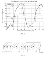
- FIG. 4 depicts a magnetic flux density distribution of a magnet unit constituted by conventional NS magnet arrays
- FIG. 5 shows a magnetic flux density distribution formed by the magnet unit in according with embodiment 1 of the present invention.
- the maximum magnetic flux density B of the conventional NS magnet arrays is 1.0501 tesla
- the maximum magnetic flux density B of the Halbach array i.e., the magnet unit comprised of the first and second magnet arrays 21 and 22, each being arranged into a similar periodically alternating configuration as a Halbach array
- embodiment 1 of the present invention is 1.8363 tesla, which shows a significant increase in the amplitude of magnetic flux density. Note that an improved magnetic flux density distribution which better resembles a standard sinusoid can be obtained by making proper adjustments in magnet array size.
- FIG. 6 shows a Y-axis coil-unit force output comparison between the linear motors of FIGs. 1 and 2
- FIG. 7 shows a Z-axis coil-unit force output comparison between structures employing a single-layered coil array and a two-layered coil array in accordance with embodiment 1 of the present invention.
- the coil-unit force output of the conventional NS magnet arrays is in a range of -42.05 ⁇ 44.17 N, while the coil-unit force output of the Halbach array in accordance with embodiment 1 is in a range of -72.54 ⁇ 74.33 N, which shows that the Halbach array in accordance with embodiment 1 of the present invention achieves a great increase in the amplitude of the coil-unit force output, compared to the prior art.
- a peak value of the coil-unit force output of a single-layered coil array employed in embodiment 1 is 4.973 N, while a peak value of the coil-unit force output of the two-layered coil array of embodiment 1 is 27.45 N, which shows that the two-layered coil array in accordance with embodiment 1 of the present invention achieves a great increase in the amplitude of the coil-unit force output in the Z-axis direction, compared to the conventional single-layered coil array.
- each of the first and second magnet arrays 21 and 22 of the above-mentioned linear motor is composed of first-type magnets 201, second-type magnets 202 and third-type magnets 203 arranged along the Y-axis direction in a similar periodically alternating manner of a Halbach array.
- Each of the third-type magnets is interposed between a corresponding first-type magnet and an adjacent second-type magnet.
- the first-type magnets 201 and second-type magnets 202 are arranged along the Y-axis direction in an alternating and equidistant manner, and each of the third-type magnets 203 is a one-piece unitary prismatic magnet or includes three prismatic magnets.
- each pair of adjacent magnets of different types has oblique abutting side faces
- each pair of adjacent ones of these three prismatic magnets has oblique abutting side faces.
- each set of a third-type magnet 203 and the adjacent first-type magnet and second-type magnet, of one magnet array jointly forms a closed magnetic circuit with a corresponding set of the other symmetrical magnet array.
- each of the first-type magnets 201 assumes a rectangular shape, in other words, each of the first-type and second-type magnets 201 and 202 is in the shape of a cuboid.
- each of the first-type and second-type magnets 201 and 202 has a magnetization direction that is parallel to the Z-axis direction, and the magnetization direction of each first-type magnet is opposite to that of each second-type magnet.
- the magnetization direction of each of the first-type magnets 201 may point toward either the positive side of the Z-axis or the opposite, negative side thereof. In this embodiment, the magnetization direction of each of the first-type magnets 201 points toward the Z-axis.
- Each of the third-type magnets 203 includes a first prismatic magnet 203a, a second prismatic magnet 203b and a third prismatic magnet 203c.
- the three prismatic magnets 203a, 203b and 203c can form, as a whole, a cuboid that is the same high as the first-type and second-type magnets 201 and 202.
- Each of the first-type magnets measures the same as each of the second-type magnets both in the lengthwise direction (i.e., the X-axis direction in this embodiment) and in the widthwise direction (i.e., the Y-axis direction in this embodiment), and the first-type, second-type and third-type magnets all have the same height (i.e., the dimension in the Z-axis direction in this embodiment).
- each of the third-type magnets 203 the pairs of adjacent prismatic magnets have oblique abutting side faces, i.e., the pair of first and second prismatic magnets 203a and 203b and the pair of the second and third prismatic magnets 203b and 203c, both have oblique abutting side faces. Additionally, each of the first, second and third prismatic magnets 203a, 203b and 203c is in the shape of a triangular or quadrangular prism.
- a path along the magnetization directions of the first, second and third prismatic magnets 203a, 203b and 203c advances, from the first prismatic magnet 203a, through the abutting faces of the first and second prismatic magnets 203a and 203b, into the second prismatic magnet 203b, further through the abutting faces of the second and third prismatic magnets 203b and 203c and further into the third prismatic magnet 203c, or reversely, from the third prismatic magnet 203c, through the abutting faces of the third and second prismatic magnets 203c and 203b, into the second prismatic magnet 203b, further through the abutting faces of the second and first prismatic magnets 203b and 203a and further into the first prismatic magnet 203a.
- each set of a third-type magnet 203 and the adjacent first-type magnet 201 and second-type magnet 202, of one magnet array jointly forms a closed magnetic circuit with a corresponding set of the other symmetric
- the Halbach topology in which the first and second magnet arrays 21 and 22 are both arranged into a periodically alternating configuration resembling a Halbach array enables the magnet unit 2 to have an augmented vertical magnetic flux and hence increased horizontal magnetic flux density and driving force, as well as an augmented horizontal magnetic flux and hence increased vertical magnetic flux density and driving force. This allows the motor to generate higher driving forces in six degrees of freedom.
- the above-mentioned first-type magnets 201 and second-type magnets 202 are all quadrangular prismatic magnets, while each of the third-type magnets 203 is comprised of triangular magnets and/or quadrangular prismatic magnets.
- the Halbach array comprised of triangular magnets and/or quadrangular prismatic magnets has less magnetic flux leakage, more uniform spatial flux density distribution, reduced high-order harmonic amplitude in in-plane flux density and a smaller mass.
- the first, second and third prismatic magnets 203a, 203b and 203c have cross sections in the Y-Z plane in the shapes of a right triangle, an isosceles triangle and a right triangle, respectively.
- angles of the abutting side faces with respect to the Z axis are determined by sizes and shapes of the first, second and third prismatic magnets 203a, 203b and 203c.
- the angle of the abutting side faces of the first and second prismatic magnets 203a and 203b relative to the Z axis and the angle of the abutting side faces of the second and third prismatic magnets 203b and 203c relative to the Z axis are equal to each other and are both determined by sizes and shapes of the first, second and third prismatic magnets 203a, 203b and 203c.
- each abutting face forms an angle of about 135° with the +Z-axis direction.
- the magnetization direction of the first prismatic magnet 203a points toward the second prismatic magnet 203b and forms an angle of about 135° with the +Z-axis direction;
- the magnetization direction of the second prismatic magnet 203b is parallel to the Y-axis direction and points toward the adjacent first-type magnet 111;
- the magnetization direction of the third prismatic magnet 203c points away from the second prismatic magnet 203b and forms an angle of about 45° with the +Z-axis direction.
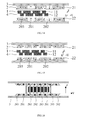
- FIG. 8 is a three-dimensional schematic view of a conventional magnet array
- FIG. 9 shows a magnetic flux density distribution along a center line of the magnet array of FIG. 8
- FIG. 10 shows the coil-unit force output of the magnet array of FIG. 1
- FIG. 11 is a three-dimensional schematic view of a magnet array used in the linear motor of FIG. 2
- FIG. 12 shows a magnetic flux density distribution along a center line of the Halbach array in accordance with embodiment 1 of the present invention
- FIG. 13 shows the coil-unit force output of the magnet array in accordance with embodiment 1 of the present invention.
- a maximum magnetic flux density created by the conventional Halbach array is 0.00036 kiloteslas; a maximum magnetic flux density of the Halbach array in accordance with embodiment 1 of the present invention is 0.00075 kiloteslas, and the magnetic flux density distribution more resembles a standard sinusoid.
- the coil-unit force output of the conventional Halbach array is in the range of -45.83 N ⁇ 48.27 N, and the coil-unit force output of the Halbach array in accordance with embodiment 1 of the present invention is -89.73 N ⁇ 79.72 N.
- this embodiment differs from embodiment 1 in that:
- this embodiment differs from embodiment 1 in that:
- each of the third-type magnets is a one-piece unitary prismatic magnet and each of the first-type, second-type and third-type magnets has a cross section in the Y-Z plane in the shape of an isosceles trapezoid. Accordingly, each of the first-type and second-type magnets has a magnetization direction that is parallel to the Z-axis direction; the magnetization direction of each of the first-type magnets is opposite to the magnetization direction of each of the second-type magnets; and each of the third-type magnets has a magnetization direction that is parallel to the Y-axis direction and points toward the adjacent first-type or second-type magnet.
- each set of a third-type magnet and the adjacent first-type and second-type magnets, of one magnet array jointly forms a closed magnetic circuit with a corresponding set of the other symmetrical magnet array.
- the cross sections of the first-type, second-type and third-type magnets in the Y-Z plane may be isosceles trapezoids that have the same length of the slant sides, the same base angle and the same height.
- the first and second magnet arrays 21 and 22, each composed of the third-type magnets 203, first-type magnets 201 and second-type magnets 202 of the above-mentioned structures, also have the advantages of generating a desirable vertical levitation force; providing a desirable control moment with ripple force that may be caused by tilt or other factors being canceled out to eliminate any torsional moment, thus achieving precision positioning; creating an augmented vertical magnetic flux and hence increased horizontal driving force; and having less magnetic flux leakage.
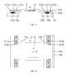
- this embodiment provides a stage apparatus 5 which includes a stage 51 and two support legs 52a and 52b disposed on opposing ends of the stage 51.
- the stage 51 is provided with a driving force in the Y-axis direction and a levitation force in the Z-axis direction from motors 53a and 53b arranged on tops of the respective support legs 52a and 52b.
- the motor 53a includes a magnet fixing member 533a, a magnet unit 531a and a coil unit 532a.
- the motor 53b includes a magnet fixing member 533b, a magnet unit 531b and a coil unit 532b.
- Each of the motors 53a and 53b is implemented as one of the above-mentioned linear motors (including the linear motors described in embodiments 1, 2 and 3).
- the stage apparatus not only obtains all the benefits thereof, but also capable of providing a driving force in a certain horizontal direction and a vertical levitation force (in the Z-axis direction), with a simple structure not including any air levitation mechanism, as well as easy operations.
- the guide means 54 includes: an air slide 541 coupled to the stage 51 and a guide rail 542 secured to the support leg 52a and/or the support leg 52b.
- the air slide 541 is disposed on a side of the guide rail 542 facing toward the stage 51.
- the air slide 541 of the stage apparatus in this embodiment is a flexible block.
- the air slide 541 and the guide rail 542 constitute an air track which takes the advantage of the working mechanism of air bearings to enable friction-free, vibration-free sliding movement. It has many advantages, such as high movement precision, cleanness and non-pollution, and capability of error equalization which allows a high guide precision resulting from a relatively low manufacture precision.
- an electrical current is introduced in the coil units 532a and 532b disposed between the magnet units 531a and 531b, and thereby causes the coil units 532a and 532b to generate a driving force along the Y-axis direction, a levitation force in the Z-axis direction that is perpendicular to the Y-axis direction, and a control moment about the X-axis direction.
- the coil unit includes a first coil array and a second coil array which are arranged in a stacked manner in the Z-axis direction and the first coil array and the second coil array are staggered from each other by a distance of ⁇ P in the Y-axis direction, and ⁇ P is so set that in the event that the coil unit is provided with a prescribed electrical current from a control system, the coil unit generates a control force along the Y-axis direction, another control force along the Z-axis direction, and a moment about the X-axis direction.
- the stage apparatus is capable of providing a driving force in a certain horizontal direction and a vertical levitation force, with a simple structure not including any air levitation mechanism, as well as easy operations.
- each of the first and second magnet arrays is composed of first-type magnets, second-type magnets and third-type magnets arranged along the Y-axis direction in a similar periodically alternating manner of a Halbach array, wherein each of the third-type magnets is interposed between a corresponding one of the first-type magnets and an adjacent one of the second-type magnets; the first-type and second-type magnets are arranged along the Y-axis direction in an alternating and equidistant manner; each of the third-type magnets is a one-piece unitary prismatic magnet or includes three prismatic magnets, where in the former case, each adjacent pair of magnets of different types has oblique abutting side faces, and in the latter case, each adjacent pair of the prismatic magnets of each of the third-type magnets has oblique abutting side faces; and each set of a third-type magnet and the adjacent first-type magnet and second-type magnet, of one magnet
- the Halbach topology in which the first and second magnet arrays are both arranged into a similar periodically alternating configuration as that of a Halbach array enables the magnet unit to have an augmented vertical magnetic flux and hence increased horizontal magnetic flux density and driving force, as well as an augmented horizontal magnetic flux and hence increased vertical magnetic flux density and driving force. This allows the motor to generate higher driving forces in six degrees of freedom.
- prismatic magnets for example, triangular or quadrangular prismatic magnets
- the use of prismatic magnets enables the construction of a Halbach array with less magnetic flux leakage, more uniform spatial flux density distribution, reduced high-order harmonic amplitude in in-plane flux density and a smaller mass, compared to the conventional magnet arrays.
Landscapes
- Engineering & Computer Science (AREA)
- Physics & Mathematics (AREA)
- Chemical & Material Sciences (AREA)
- Combustion & Propulsion (AREA)
- Electromagnetism (AREA)
- Power Engineering (AREA)
- Linear Motors (AREA)
- Exposure And Positioning Against Photoresist Photosensitive Materials (AREA)
Applications Claiming Priority (3)
| Application Number | Priority Date | Filing Date | Title |
|---|---|---|---|
| CN201210270584.5A CN103580444B (zh) | 2012-07-31 | 2012-07-31 | 直线电机 |
| CN201210525941.8A CN103872876A (zh) | 2012-12-07 | 2012-12-07 | 直线电机及平台装置 |
| PCT/CN2013/078671 WO2014019438A1 (fr) | 2012-07-31 | 2013-07-02 | Moteur linéaire et dispositif de plateforme |
Publications (2)
| Publication Number | Publication Date |
|---|---|
| EP2882082A1 true EP2882082A1 (fr) | 2015-06-10 |
| EP2882082A4 EP2882082A4 (fr) | 2015-12-09 |
Family
ID=50027216
Family Applications (1)
| Application Number | Title | Priority Date | Filing Date |
|---|---|---|---|
| EP13826225.8A Withdrawn EP2882082A4 (fr) | 2012-07-31 | 2013-07-02 | Moteur linéaire et dispositif de plateforme |
Country Status (4)
| Country | Link |
|---|---|
| US (1) | US9755493B2 (fr) |
| EP (1) | EP2882082A4 (fr) |
| SG (1) | SG11201407672XA (fr) |
| WO (1) | WO2014019438A1 (fr) |
Cited By (2)
| Publication number | Priority date | Publication date | Assignee | Title |
|---|---|---|---|---|
| WO2017211510A1 (fr) * | 2016-06-09 | 2017-12-14 | Asml Netherlands B.V. | Procédé de fabrication d'un appareil et d'un dispositif de lithographie |
| CN109698600A (zh) * | 2018-12-10 | 2019-04-30 | 中国科学院电工研究所 | 一种具有辅助弱磁结构的直线电机 |
Families Citing this family (19)
| Publication number | Priority date | Publication date | Assignee | Title |
|---|---|---|---|---|
| KR20140084238A (ko) | 2011-10-27 | 2014-07-04 | 더 유니버시티 오브 브리티쉬 콜롬비아 | 변위 장치 및 변위 장치의 제조, 사용 그리고 제어를 위한 방법 |
| CN105452812B (zh) | 2013-08-06 | 2019-04-30 | 不列颠哥伦比亚大学 | 移位装置以及用于检测和估计与其相关联的运动的方法和设备 |
| US9786423B2 (en) * | 2013-10-28 | 2017-10-10 | Massachusetts Institute Of Technology | Method and apparatus for producing an asymmetric magnetic field |
| WO2015179962A1 (fr) * | 2014-05-30 | 2015-12-03 | The University Of British Columbia | Dispositifs de déplacement et leurs procédés de fabrication, d'utilisation et de commande |
| EP3152822B1 (fr) | 2014-06-07 | 2019-08-07 | The University Of British Columbia | Procédés et systèmes de mouvement commandé de plusieurs étages mobiles dans un dispositif de déplacement |
| WO2015188281A1 (fr) | 2014-06-14 | 2015-12-17 | The University Of British Columbia | Dispositifs de déplacement, étages mobiles pour dispositifs de déplacement et leurs procédés de fabrication, d'utilisation et de commande |
| CN105811730B (zh) * | 2014-12-30 | 2018-06-29 | 上海微电子装备(集团)股份有限公司 | 一种六自由度直线电机 |
| CN104660003B (zh) * | 2015-02-02 | 2017-05-10 | 瑞声光电科技(常州)有限公司 | 扁平线性振动电机 |
| JP2016152668A (ja) * | 2015-02-17 | 2016-08-22 | 住友重機械工業株式会社 | リニアモータ、磁石ユニット、ステージ装置 |
| CA2988803C (fr) | 2015-07-06 | 2024-01-30 | The University Of British Columbia | Procedes et systemes de mouvement commandable d'un ou plusieurs etages mobiles dans un dispositif a deplacement |
| DE102015115347A1 (de) | 2015-09-11 | 2017-03-16 | Beckhoff Automation Gmbh | Magnetanordnung für einen elektrischen Motor |
| CN106936337B (zh) * | 2015-12-30 | 2019-02-01 | 上海微电子装备(集团)股份有限公司 | 磁浮平面旋转电机及光刻装置 |
| US10671166B2 (en) * | 2016-08-26 | 2020-06-02 | Apple Inc. | Electronic device including Halbach array based haptic actuator and related methods |
| US11223303B2 (en) * | 2017-06-19 | 2022-01-11 | Nikon Research Corporation Of America | Motor with force constant modeling and identification for flexible mode control |
| KR102533589B1 (ko) * | 2018-04-17 | 2023-05-17 | 자화전자(주) | 수평형 리니어 진동발생장치 |
| EP3719962A1 (fr) | 2019-04-01 | 2020-10-07 | LIM-Tech Limited | Machine électromotrice |
| DE102019113296A1 (de) * | 2019-05-20 | 2020-11-26 | Physik Instrumente (Pi) Gmbh & Co. Kg | Zweiachspositioniervorrichtung |
| CN112382459B (zh) * | 2020-10-30 | 2025-05-27 | 苏州英磁新能源科技有限公司 | 一种三角形电磁铁单元 |
| CN116961356B (zh) * | 2023-09-19 | 2023-12-12 | 中国科学院长春光学精密机械与物理研究所 | 一种可提供动子z向浮力的长行程运动电机 |
Family Cites Families (14)
| Publication number | Priority date | Publication date | Assignee | Title |
|---|---|---|---|---|
| JPH0433564A (ja) | 1990-05-30 | 1992-02-04 | Hitachi Metals Ltd | 3相駆動方式リニアブラシレス直流モータ |
| JP3916048B2 (ja) * | 2002-01-10 | 2007-05-16 | 株式会社安川電機 | リニアモータ |
| JP2004172557A (ja) * | 2002-11-22 | 2004-06-17 | Canon Inc | ステージ装置及びその制御方法 |
| EP1457826A1 (fr) | 2003-03-11 | 2004-09-15 | ASML Netherlands B.V. | Appareil lithographique et procédé pour la production d'un dispositif |
| US6906789B2 (en) * | 2003-06-02 | 2005-06-14 | Asml Holding N.V. | Magnetically levitated and driven reticle-masking blade stage mechanism having six degrees freedom of motion |
| US7368838B2 (en) * | 2004-11-02 | 2008-05-06 | Nikon Corporation | High efficiency voice coil motor |
| WO2008130560A1 (fr) * | 2007-04-19 | 2008-10-30 | Nikon Corporation | Dispositif de déplacement à trois degrés de mouvement et procédé de commande d'un tel dispositif |
| US20100090545A1 (en) * | 2008-10-09 | 2010-04-15 | Binnard Michael B | Planar motor with wedge shaped magnets and diagonal magnetization directions |
| JP5188357B2 (ja) * | 2008-10-23 | 2013-04-24 | 三菱電機株式会社 | リニアモータ |
| US7808133B1 (en) * | 2009-04-21 | 2010-10-05 | Asm Assembly Automation Ltd. | Dual-axis planar motor providing force constant and thermal stability |
| US8115348B2 (en) | 2009-05-22 | 2012-02-14 | Chieftek Precision Co., Ltd. | Unit coil, coil assembly and coreless type linear motor |
| JP5369926B2 (ja) | 2009-06-19 | 2013-12-18 | 株式会社安川電機 | リニアモータの電機子およびリニアモータ |
| CN101783574B (zh) | 2010-04-12 | 2012-04-25 | 哈尔滨工业大学 | 环形绕组分段式永磁同步直线电机 |
| CN102185458B (zh) | 2011-05-18 | 2013-03-27 | 哈尔滨工业大学 | 高精度无槽永磁电机 |
-
2013
- 2013-07-02 US US14/408,130 patent/US9755493B2/en active Active
- 2013-07-02 SG SG11201407672XA patent/SG11201407672XA/en unknown
- 2013-07-02 WO PCT/CN2013/078671 patent/WO2014019438A1/fr not_active Ceased
- 2013-07-02 EP EP13826225.8A patent/EP2882082A4/fr not_active Withdrawn
Cited By (3)
| Publication number | Priority date | Publication date | Assignee | Title |
|---|---|---|---|---|
| WO2017211510A1 (fr) * | 2016-06-09 | 2017-12-14 | Asml Netherlands B.V. | Procédé de fabrication d'un appareil et d'un dispositif de lithographie |
| US10955759B2 (en) | 2016-06-09 | 2021-03-23 | Asml Netherlands B.V. | Lithographic apparatus and device manufacturing method |
| CN109698600A (zh) * | 2018-12-10 | 2019-04-30 | 中国科学院电工研究所 | 一种具有辅助弱磁结构的直线电机 |
Also Published As
| Publication number | Publication date |
|---|---|
| WO2014019438A1 (fr) | 2014-02-06 |
| US20150137624A1 (en) | 2015-05-21 |
| SG11201407672XA (en) | 2015-04-29 |
| US9755493B2 (en) | 2017-09-05 |
| EP2882082A4 (fr) | 2015-12-09 |
Similar Documents
| Publication | Publication Date | Title |
|---|---|---|
| US9755493B2 (en) | Linear motor and stage apparatus | |
| CN101610054B (zh) | 采用三维永磁阵列的平面电机 | |
| US8044541B2 (en) | Multi-degree-of-freedom actuator and stage device | |
| CN103208867B (zh) | 磁铁单元、磁铁阵列、磁浮平面电机及应用该磁浮平面电机的光刻装置 | |
| US20100187917A1 (en) | Micro stage with 6 degrees of freedom | |
| JP6410945B2 (ja) | 6自由度リニアモータ | |
| CN101214617B (zh) | 动圈式大范围移动磁浮六自由度工作台 | |
| JP5575802B2 (ja) | 一体式ステージ位置決めシステム及び方法 | |
| CN101694560B (zh) | 采用气浮平面电机的硅片台双台交换系统 | |
| CN103872876A (zh) | 直线电机及平台装置 | |
| CN110429868B (zh) | 低刚度的磁悬浮重力补偿器、驱动装置及六自由度微动台 | |
| US20020070699A1 (en) | Stage apparatus including non-containing gas bearings and microlithography apparatus comprising same | |
| CN103226295A (zh) | 一种光刻机硅片台微动工作台 | |
| CN103454864B (zh) | 一种粗精动一体的磁浮掩膜台系统 | |
| US12149143B2 (en) | Magnetic levitation planar motor workbench having double-layer winding of coarse and fine drive | |
| CN103226296A (zh) | 一种带激光干涉仪测量的粗精动叠层工作台 | |
| CN103383526B (zh) | 一种粗精动叠层工作台 | |
| JP2004172557A (ja) | ステージ装置及びその制御方法 | |
| CN103580444B (zh) | 直线电机 | |
| JP5140103B2 (ja) | リニアモータ対、移動ステージ、及び電子顕微鏡 | |
| CN203275876U (zh) | 一种光刻机硅片台微动工作台 | |
| CN112436711B (zh) | 位移装置 | |
| CN106300874B (zh) | 一种多自由度长行程直线电机 | |
| Kim et al. | Design and control of a 6-DOF high-precision integrated positioner | |
| KR20230153263A (ko) | 스테이지 장치, 전사장치 및 물품제조방법 |
Legal Events
| Date | Code | Title | Description |
|---|---|---|---|
| PUAI | Public reference made under article 153(3) epc to a published international application that has entered the european phase |
Free format text: ORIGINAL CODE: 0009012 |
|
| 17P | Request for examination filed |
Effective date: 20150114 |
|
| AK | Designated contracting states |
Kind code of ref document: A1 Designated state(s): AL AT BE BG CH CY CZ DE DK EE ES FI FR GB GR HR HU IE IS IT LI LT LU LV MC MK MT NL NO PL PT RO RS SE SI SK SM TR |
|
| AX | Request for extension of the european patent |
Extension state: BA ME |
|
| DAX | Request for extension of the european patent (deleted) | ||
| RA4 | Supplementary search report drawn up and despatched (corrected) |
Effective date: 20151110 |
|
| RIC1 | Information provided on ipc code assigned before grant |
Ipc: H02K 41/02 20060101AFI20151104BHEP |
|
| STAA | Information on the status of an ep patent application or granted ep patent |
Free format text: STATUS: THE APPLICATION IS DEEMED TO BE WITHDRAWN |
|
| 18D | Application deemed to be withdrawn |
Effective date: 20160608 |