EP2882620B1 - Essuie-glace - Google Patents
Essuie-glace Download PDFInfo
- Publication number
- EP2882620B1 EP2882620B1 EP12773375.6A EP12773375A EP2882620B1 EP 2882620 B1 EP2882620 B1 EP 2882620B1 EP 12773375 A EP12773375 A EP 12773375A EP 2882620 B1 EP2882620 B1 EP 2882620B1
- Authority
- EP
- European Patent Office
- Prior art keywords
- adapter
- arm
- bracket
- connection device
- locking means
- Prior art date
- Legal status (The legal status is an assumption and is not a legal conclusion. Google has not performed a legal analysis and makes no representation as to the accuracy of the status listed.)
- Active
Links
Images



Classifications
-
- B—PERFORMING OPERATIONS; TRANSPORTING
- B60—VEHICLES IN GENERAL
- B60S—SERVICING, CLEANING, REPAIRING, SUPPORTING, LIFTING, OR MANOEUVRING OF VEHICLES, NOT OTHERWISE PROVIDED FOR
- B60S1/00—Cleaning of vehicles
- B60S1/02—Cleaning windscreens, windows or optical devices
- B60S1/04—Wipers or the like, e.g. scrapers
- B60S1/32—Wipers or the like, e.g. scrapers characterised by constructional features of wiper blade arms or blades
- B60S1/38—Wiper blades
- B60S1/3848—Flat-type wiper blade, i.e. without harness
- B60S1/3849—Connectors therefor; Connection to wiper arm; Attached to blade
- B60S1/3865—Connectors having an integral pivot pin for connection with the wiper arm
- B60S1/3868—Connectors having an integral pivot pin for connection with the wiper arm pin formed on the exterior of side walls
-
- B—PERFORMING OPERATIONS; TRANSPORTING
- B60—VEHICLES IN GENERAL
- B60S—SERVICING, CLEANING, REPAIRING, SUPPORTING, LIFTING, OR MANOEUVRING OF VEHICLES, NOT OTHERWISE PROVIDED FOR
- B60S1/00—Cleaning of vehicles
- B60S1/02—Cleaning windscreens, windows or optical devices
- B60S1/04—Wipers or the like, e.g. scrapers
- B60S1/32—Wipers or the like, e.g. scrapers characterised by constructional features of wiper blade arms or blades
- B60S1/38—Wiper blades
- B60S1/3848—Flat-type wiper blade, i.e. without harness
- B60S1/3849—Connectors therefor; Connection to wiper arm; Attached to blade
- B60S1/3865—Connectors having an integral pivot pin for connection with the wiper arm
- B60S1/3867—Connectors having an integral pivot pin for connection with the wiper arm pin formed on the interior of side walls
-
- B—PERFORMING OPERATIONS; TRANSPORTING
- B60—VEHICLES IN GENERAL
- B60S—SERVICING, CLEANING, REPAIRING, SUPPORTING, LIFTING, OR MANOEUVRING OF VEHICLES, NOT OTHERWISE PROVIDED FOR
- B60S1/00—Cleaning of vehicles
- B60S1/02—Cleaning windscreens, windows or optical devices
- B60S1/04—Wipers or the like, e.g. scrapers
- B60S1/32—Wipers or the like, e.g. scrapers characterised by constructional features of wiper blade arms or blades
- B60S1/40—Connections between blades and arms
- B60S1/4038—Connections between blades and arms for arms provided with a channel-shaped end
- B60S1/4045—Connections between blades and arms for arms provided with a channel-shaped end comprising a detachable intermediate element mounted on the channel-shaped end
- B60S1/4048—Connections between blades and arms for arms provided with a channel-shaped end comprising a detachable intermediate element mounted on the channel-shaped end the element being provided with retention means co-operating with the channel-shaped end of the arm
-
- B—PERFORMING OPERATIONS; TRANSPORTING
- B60—VEHICLES IN GENERAL
- B60S—SERVICING, CLEANING, REPAIRING, SUPPORTING, LIFTING, OR MANOEUVRING OF VEHICLES, NOT OTHERWISE PROVIDED FOR
- B60S1/00—Cleaning of vehicles
- B60S1/02—Cleaning windscreens, windows or optical devices
- B60S1/04—Wipers or the like, e.g. scrapers
- B60S1/32—Wipers or the like, e.g. scrapers characterised by constructional features of wiper blade arms or blades
- B60S1/40—Connections between blades and arms
- B60S1/4038—Connections between blades and arms for arms provided with a channel-shaped end
- B60S1/4045—Connections between blades and arms for arms provided with a channel-shaped end comprising a detachable intermediate element mounted on the channel-shaped end
- B60S1/4048—Connections between blades and arms for arms provided with a channel-shaped end comprising a detachable intermediate element mounted on the channel-shaped end the element being provided with retention means co-operating with the channel-shaped end of the arm
- B60S2001/4054—Connections between blades and arms for arms provided with a channel-shaped end comprising a detachable intermediate element mounted on the channel-shaped end the element being provided with retention means co-operating with the channel-shaped end of the arm the intermediate element engaging the back part of the arm
Definitions
- the present invention relates to an attachment device for connecting a windscreen wiper blade to a wiper arm in vehicles such as automobiles.
- a windscreen wiper device comprising an elastic wiper profile for wiping the surface of the windscreen, an elongated, resilient carrier frame for supporting said profile and a connecting device for an oscillating wiper arm have been known for a long time.
- the wiper blade In order to ensure the proper contact between the wiper profile and the windscreen surface at every point, the wiper blade should be pivotally connected to the free end of the wiper arm so as to rotate around a pivot axis. Such a rotatable connection is required to be secure enough at one hand to resist the forces acting in all three directions, and on the other hand, should be easily detachable to enable the end user to replace the wiper blade when needed.
- One of the arm-blade connections meeting said requirements is the bayonet design.
- EP1568559 discloses such an arm-blade connection which is realized by an adapter part that can be attached to a bracket fixed on the wiper blade by pivotally engaging pin-shaped lateral protrusions of said bracket in holes provided in said adapter part.
- the holes have a closed circumference to enhance the retention of the arm onto the bracket/adapter in horizontal and vertical directions whereas the longitudinal retention is enhanced by a resilient tongue provided on the adapter engaging in a correspondingly shaped hole provided in the arm.
- the disclosed adapter part can be mounted onto the bracket by resiliently stretching the side walls outwards. However in case the user applies excessive force during assembly, the adapter may lose its function.
- US2006272119 discloses an adapter for connecting a U-shaped arm with a carrier frame of a conventional type wiper blade.
- the disclosed adapter comprises a resilient tongue engaging in a hole in said oscillating arm to lock with the arm in the longitudinal direction.
- the lateral surfaces of the arm and the adapter surrounding each other enhance the vertical locking between the arm and the adapter.
- the adapter-blade therefore the arm-blade connection is not safe against the forces that may act in the vertical direction.
- the adapter is pivotally mounted on the pin of the carrier frame by means of a recess formed in a downwardly extending portion of the adapter.
- the recess is provided with an insertion opening such that the adapter can be snapped onto the pin by a simple vertical movement.
- Document EP2143603 A2 discloses a connecting device for connecting a wiper blade according to the preamble of claim 1.
- FR2890925 discloses an adapter which can be attached to the bracket in a vertical direction.
- Circular protrusions serving as pins are situated on the two parallel lateral surfaces of the bracket, and the articulated connection is realized by said protrusions being seated into the openings arranged on the two lateral surfaces of the adapter.
- Said openings have an open circumference formed by elastically deformable attachment portions such that said portions can deflect outwards during snapping onto the pin-like protrusions, and after assembly, they return elastically to their initial position and prevent the vertical movement of the pin-like protrusions through the opening.
- the connection between the arm is again realized by a resilient tongue provided on the adapter engaging in a corresponding hole provided on the arm.
- connection mechanism that enables the adapter to be easily fastened to the blade without being damaged during the mounting and that provides the arm and the blade to be locked in a safe manner against the forces in all directions.
- connection mechanism that provides the safe connection of the arm and the blade and the easy-attachment and detachment thereof is disclosed.
- connection mechanism is claimed in claim 1 and first a bracket which is fixed at approximately the central region of the blade by preferably gripping the vertebra with its hook-shaped legs.
- a pin is disposed between the parallel side walls of the bracket and protrusions are provided on the outer surface of said side walls.
- the adapter on the other hand, is provided with two resilient arms extending downwards from the inner surface of its top wall and form an inverted U-shaped pin housing. This pin housing is snapped onto the pin located between the two side walls of the bracket and provides an articulated connection between the adapter and the bracket.
- the free end of the arm which has a U -shaped form composed of a top and two side walls and a hole arranged on said top wall, is locked into engagement with the adapter as well as with the bracket as it is mounted onto the adapter.
- the arm-adapter locking is realized by means of a resilient tongue provided on the adapter entering into the hole on the arm so as to secure the arm on the blade in the longitudinal direction.
- a second locking which acts against forces in the vertical direction is provided between the arm and the bracket.
- this second locking is realized by means of at least one locking member located on the inner surface of the side wall of the arm, engaging with the protrusion on the outer surface of the bracket.
- at least one of the contact surfaces of this second locking components is provided in a curvilinear form.
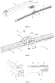
- connection is used for connecting a wiper blade (4) having at least one elastomeric wiper profile (7) with a lip portion for wiping the glass surface, an arc-shaped resilient metal vertebra (6) and a bracket (3) fixed to the vertebra (6) at the longitudinal middle region, to a wiper arm (1) one end of which is connected to a motor in the vehicle so as to rotate around a pivot axis (8).
- the connection according to the present invention comprises said bracket (3), an adapter (2) connected to the bracket (3) so as to rotate around said pivot axis (8) and the free end (10) of the wiper arm (1) which is fastened to these two elements (2, 3).
- the bracket (3) is fixed to the blade (4), preferably directly to the vertebra (6) by means of its hook-shaped legs (32).
- the body portion (30) above these legs (32) has preferably two parallel side walls (31).
- a pin (33) preferably having a circular cross-section extends between said two side walls (31) and joins them.
- At least one protrusion (34) is provided on the outer surface (310) of at least one, preferably both of the side walls (31).
- the lower surface (340) of each protrusion (34) has a curvilinear form.
- said surfaces (340) may also have a flat form.
- Said protrusions (34) are preferably arranged in crescent-shaped with tops open; however, they can have different shapes provided that they do not obstruct the movement of the blade (4) on the windscreen.
- the free end (10) of the wiper arm (1) is composed of two parallel side walls (11) and a top wall (12) joining these two (11).
- a hole (13) is arranged on the top wall (12) and is preferably formed as quadrangular.
- Inner surfaces (110) of at least one, preferably both of said side walls (11) are provided with at least one locking member (111) .
- said locking members (111) are provided so as to have a planar upper surface (112); however, in other embodiments of the invention, the locking members (111) may have circular or elliptical cross-sections.
- the adapter (2) is composed of a head portion (21) and a body (20) with U-shaped cross-section which comprises two side walls (22) and a top wall (23).
- the head (21) has a protruding structure with respect to the body (20) so as to form an abutment surface (210) at the region where it intersects the body (20).
- the top wall (23) of the body (20) has one or more than one tongues (24).
- the tongue (24) is preferably quadrangular and designed so as to be inserted into the hole (13) on the free end (10) of the arm (1).
- a pin housing (25) that grips the pin (33) on the bracket (3) in the assembled state is formed on the inner surface (230) of the top wall (20).
- the pin housing (25) is in the form of an inverted U and is preferably formed by means of two arc-shaped flexible extensions (251) that extend downwards.
- side members (26) are arranged on both side walls (22) of the body (20) of the adapter (2) in order to bear the protrusions (34) of the bracket (3).
- Said side members (26) have preferably circular cross-sections and aligned with the pin housing (25).
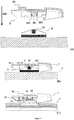
- Figure 5 and 6 show the assembly process of the wiper arm (1) and the wiper blade (4).
- Figure 5a shows the connection of the adapter (2) to the bracket (3) that is fixed on the blade (4).
- the adapter In order to mount the adapter (2) onto the bracket (3), the adapter is moved in the vertical direction (400) as shown in the figure.
- the flexible extensions (251) of the adapter (2) stretch outwards and open, then surround the pin (33) at the center of the bracket (3).
- the adapter (2) is connected to the blade (4) in an articulated manner.
- side walls (22) of the adapter (2) surround the side walls (31) of the bracket (3).
- the protrusions (34) of the bracket (3) and the side members (26) of the adapter (2) stands on each other.
- Figure 6a shows the assembly of the arm (1) on the blade.
- the assembly is realized by sliding the arm (1) over the adapter (2) in the longitudinal direction (500) until its front surface (14) bears against the abutment surface (210) of the adapter.
- the locking members (111) on side walls pass underneath the lateral protrusions (34) of the bracket (3).
- a first locking is obtained between the free end of the arm and the bracket.
- the tongue (24) engages in the hole (13) of the arm, providing a second locking between the free end of the arm and the adapter.
- Figure 6b shows the inventive connection in the assembled state.
- the free end of the arm (10) is fastened to the bracket.
- any possibility of detachment of the arm and the blade due to forces in the vertical direction is eliminated.
- the planar upper surfaces (112) of the locking members (111) and the curvilinear lower surfaces (340) of the protrusions (34) resting on them (112) thanks to the planar upper surfaces (112) of the locking members (111) and the curvilinear lower surfaces (340) of the protrusions (34) resting on them (112), the rocking motion between the arm and the bracket is preserved.
- the rotational movement between the arm (1) and the blade (4) is not limited.
- Figure 7 shows an alternative embodiment of the wiper connection of the present invention.
- the lower surfaces (340') of the protrusions (34') on the bracket (3') are flat.
- the surface (112') of the locking members (111') that contacts the lower surfaces (340') has a curvilinear shape.
- the shapes of the locking members (111, 111') and the protrusions (34, 34') of the bracket (3, 3') are not limited to the shapes in the figures and various designs can be used as long as they do not limit the movement of the wiper.
Landscapes
- Engineering & Computer Science (AREA)
- Mechanical Engineering (AREA)
- Pivots And Pivotal Connections (AREA)
- Insertion Pins And Rivets (AREA)
Claims (14)
- Dispositif de raccordement pour raccorder, à un bras d'essuie-glaces (1) pendulant de manière à pivoter autour d'un axe de pivotement (8), un balai d'essuie-glaces (4) ayant au moins un profil de balayage (7) en élastomère avec une partie labiale pour balayer la surface en verre, un élément porteur (6) résilient en forme d'arc et un support (3) fixé au balai (4) de préférence en une région centrale longitudinale ;
le dispositif comprenant au moins ledit support (3), un adaptateur (2) attaché de manière pivotante au support (3) et l'extrémité libre (10) du bras d'essuie-glaces (1) ; dans lequel le dispositif comprend un premier moyen de verrouillage (34, 111, 34', 111") et un second moyen de verrouillage (13, 24), de manière à ce que ledit premier moyen de verrouillage (34, 111, 34', 111') fixe le bras sur le support (3) et le second moyen de verrouillage (13, 24) fixe le bras sur l'adaptateur (2), et
ledit premier moyen de verrouillage (34, 111) comprend une protubérance (34) prévu sur au moins une, de préférence sur les deux parois latérales (31) du support (3), de manière à faire saillie vers l'extérieur,
caractérisé en ce que ledit premier moyen de verrouillage comprend en outre un élément de verrouillage (111) prévu sur la surface interne (110) d'au moins une, de préférence des deux parois latérales (11) de l'extrémité libre (10) du bras (1) de manière à faire saillie vers l'intérieur et à être engagé avec ledit protubérance (34). - Dispositif de raccordement selon la revendication précédente, caractérisé en ce que les surfaces de contact dudit premier moyen de verrouillage (34, 111) engagées l'une avec l'autre comprennent la surface inférieure (340) de ladite protubérance (34) et la surface supérieure (112) dudit élément de verrouillage (111).
- Dispositif de raccordement selon la revendication précédente, caractérisé en ce qu'au moins une desdits surfaces de contact (340, 112) présente une forme curvilinéaire de manière à ce que l'extrémité libre (10) du bras (1) est fixable au support (3) de manière à pivoter autour dudit axe de pivotement (8).
- Dispositif de raccordement selon la revendication 3, caractérisé en ce que la surface inférieure (340) de la protubérance (34) présente une forme curvilinéaire et la surface supérieure (112) de l'élément de verrouillage (114) du bras (1) est plate.
- Dispositif de raccordement selon la revendication 3, caractérisé en ce que la surface inférieure (340') de la protubérance (34') présente une forme planaire et ; la surface supérieure (112") de l'élément de verrouillage (111) du bras (1) est curvilinéaire.
- Dispositif de raccordement selon la revendication 1, caractérisé en ce que ledit second moyen de verrouillage (13, 24) comprend au moins un trou (13) prévu sur l'extrémité libre (10) du bras (1) et ; au moins une protubérance (24) en forme de languette prévue sur l'adaptateur (2) de manière à être engagée dans ledit trou (13).
- Dispositif de raccordement selon l'une quelconque des revendications précédentes, caractérisé en ce que ledit adaptateur (2) comprend une partie de tête (21) et un corps (20) ayant une coupe transversale en forme de U comprenant deux parois latérales (22) et une paroi supérieure (23).
- Dispositif de raccordement selon la revendication précédente, dans lequel ladite partie de tête (21) présente une structure faisant saillie par rapport au corps (20) de manière à former une surface d'appui (210) à la région où il entrecroise le corps (20).
- Dispositif de raccordement selon l'une quelconque des revendications précédentes, caractérisé en ce que le raccordement articulé dudit support (3) et de l'adaptateur (2) est obtenu par une goupille (33) prévu sur le support (3) et un logement de goupille (25) formé sur l'adaptateur (2), dans lequel ladite goupille (33) est engagée.
- Dispositif de raccordement selon la revendication précédente, caractérisé en ce que ledit logement de goupille (25) est formé par deux rallonges flexibles (251) en forme d'arc, qui s'étendent de préférence à partir de la surface interne (230) de la paroi supérieure (23) de l'adaptateur (2).
- Dispositif de raccordement selon la revendication précédente, caractérisé en ce que ledit logement (25) a un fond ouvert et lesdits rallonges flexibles (251) ont une structure s'étendant vers l'extérieur pour leur permettre de saisir la goupille (33) afin de monter ledit adaptateur (2) sur ledit support (3) dans la direction verticale (400).
- Dispositif de raccordement selon la revendication 8, caractérisé en ce que l'extrémité libre (10) du bras (1) glisse au-dessus de l'adaptateur dans la direction (500) longitudinale jusqu'à ce que sa surface frontale (14) contacte ladite surface d'appui (210) de l'adaptateur (2) de manière à ce que ledit bras (1) puisse être verrouillé avec ledit adaptateur (2) et le support (3).
- Dispositif de raccordement selon les revendications précédentes, caractérisé en ce que des pièces latérales (26) sont disposés au moins sur une ou les deux parois latérales (22) du corps (20) de l'adaptateur (2) de manière à supporter lesdites protubérances (34) du support (3).
- Dispositif de raccordement selon la revendication précédente, caractérisé en ce que lesdites pièces latérales (26) ont des coupes transversales circulaires.
Priority Applications (1)
| Application Number | Priority Date | Filing Date | Title |
|---|---|---|---|
| PL12773375T PL2882620T3 (pl) | 2012-08-13 | 2012-08-13 | Wycieraczka przedniej szyby |
Applications Claiming Priority (1)
| Application Number | Priority Date | Filing Date | Title |
|---|---|---|---|
| PCT/IB2012/054109 WO2014027217A1 (fr) | 2012-08-13 | 2012-08-13 | Essuie-glace |
Publications (2)
| Publication Number | Publication Date |
|---|---|
| EP2882620A1 EP2882620A1 (fr) | 2015-06-17 |
| EP2882620B1 true EP2882620B1 (fr) | 2019-07-03 |
Family
ID=47040763
Family Applications (1)
| Application Number | Title | Priority Date | Filing Date |
|---|---|---|---|
| EP12773375.6A Active EP2882620B1 (fr) | 2012-08-13 | 2012-08-13 | Essuie-glace |
Country Status (5)
| Country | Link |
|---|---|
| US (1) | US10144393B2 (fr) |
| EP (1) | EP2882620B1 (fr) |
| PL (1) | PL2882620T3 (fr) |
| RU (1) | RU2597625C1 (fr) |
| WO (1) | WO2014027217A1 (fr) |
Families Citing this family (3)
| Publication number | Priority date | Publication date | Assignee | Title |
|---|---|---|---|---|
| FR3047711B1 (fr) * | 2016-02-12 | 2019-05-03 | Valeo Systemes D'essuyage | Adaptateur constitutif d’un systeme d’essuyage. |
| US10150452B2 (en) | 2016-10-14 | 2018-12-11 | Federal-Mogul Motorparts Llc | Windscreen wiper device |
| EP4667299A1 (fr) * | 2024-06-20 | 2025-12-24 | Danyang UPC Auto Parts Co., Ltd. | Structure d'essuie-glace et accessoire d'essuie-glace associé |
Citations (1)
| Publication number | Priority date | Publication date | Assignee | Title |
|---|---|---|---|---|
| EP2755874A1 (fr) * | 2011-09-12 | 2014-07-23 | Valeo Systèmes d'Essuyage | Ensemble de connexion pour systeme d'essuyage d'un vehicule automobile |
Family Cites Families (11)
| Publication number | Priority date | Publication date | Assignee | Title |
|---|---|---|---|---|
| DE10046439A1 (de) * | 2000-09-20 | 2002-04-04 | Bosch Gmbh Robert | Scheibenwischer |
| DE10162401A1 (de) * | 2001-12-19 | 2003-07-10 | Bosch Gmbh Robert | Scheibenwischer mit einem Wischarm |
| DE10257991A1 (de) * | 2002-04-04 | 2004-02-05 | Robert Bosch Gmbh | Wischhebel mit einem angetriebenen Wischerarm und einem an diesem angelenkten Wischblatt zum Reinigen von Scheiben insbesondere von Kraftfahrzeugen |
| ES2287641T3 (es) | 2004-02-26 | 2007-12-16 | Federal-Mogul S.A. | Un dispositivo de limpiaparabrisas. |
| US7398577B2 (en) | 2005-06-03 | 2008-07-15 | Federal - Mogul S.A. | Windscreen wiper device |
| FR2890925B1 (fr) | 2005-09-21 | 2009-12-25 | Valeo Systemes Dessuyage | Connecteur de montage et d'articulation d'un balai d'essuyage sur l'extremite d'un bras d'entrainement |
| DE602006008768D1 (de) * | 2006-07-06 | 2009-10-08 | Federal Mogul Sa | Scheibenwischervorrichtung |
| US8286298B2 (en) | 2008-07-11 | 2012-10-16 | Adm21 Co., Ltd. | Device for connecting a flat wiper blade to wiper arms |
| DE102009029458A1 (de) * | 2009-09-15 | 2011-03-24 | Robert Bosch Gmbh | Anschlussvorrichtung |
| DE102010030880A1 (de) * | 2010-07-02 | 2012-01-05 | Robert Bosch Gmbh | Anschlussvorrichtung zum gelenkigen Verbinden eines Wischarms mit einem Wischblatt |
| DE102010056366A1 (de) * | 2010-12-29 | 2012-07-05 | Valeo Systèmes d'Essuyage | Wischblatt zum Reinigen von Scheiben von Kraftfahrzeugen und Wischarm |
-
2012
- 2012-08-13 US US14/421,090 patent/US10144393B2/en active Active
- 2012-08-13 RU RU2015108741/11A patent/RU2597625C1/ru active
- 2012-08-13 WO PCT/IB2012/054109 patent/WO2014027217A1/fr not_active Ceased
- 2012-08-13 EP EP12773375.6A patent/EP2882620B1/fr active Active
- 2012-08-13 PL PL12773375T patent/PL2882620T3/pl unknown
Patent Citations (1)
| Publication number | Priority date | Publication date | Assignee | Title |
|---|---|---|---|---|
| EP2755874A1 (fr) * | 2011-09-12 | 2014-07-23 | Valeo Systèmes d'Essuyage | Ensemble de connexion pour systeme d'essuyage d'un vehicule automobile |
Also Published As
| Publication number | Publication date |
|---|---|
| WO2014027217A1 (fr) | 2014-02-20 |
| US10144393B2 (en) | 2018-12-04 |
| US20150197217A1 (en) | 2015-07-16 |
| EP2882620A1 (fr) | 2015-06-17 |
| PL2882620T3 (pl) | 2020-03-31 |
| RU2597625C1 (ru) | 2016-09-10 |
Similar Documents
| Publication | Publication Date | Title |
|---|---|---|
| US10766462B2 (en) | Windshield wiper connector | |
| US10661759B2 (en) | Windshield wiper connector | |
| US8959701B2 (en) | Multi-adapter for a vehicle wiper | |
| CN106627499B (zh) | 用于风挡雨刮器刷的连接系统的元件 | |
| US9855923B2 (en) | Wiper blade | |
| US20110239396A1 (en) | Windscreen wiper device | |
| KR20110039390A (ko) | 차량 앞유리 와이퍼의 와이퍼 암에 와이퍼 블레이드를 관절식으로 연결하기 위한 장치 | |
| CA2809292A1 (fr) | Unite de raccordement pour bras d'essuie-glace et balai d'essuie-glace plat comprenant cette derniere | |
| WO2012014054A1 (fr) | Dispositif de connexion d'essuie glace | |
| KR20150027051A (ko) | 차창 와이퍼 장치 | |
| US9862356B2 (en) | Wiper blade | |
| WO2015175604A1 (fr) | Dispositif essuie-glace | |
| EP2882620B1 (fr) | Essuie-glace | |
| US11097693B2 (en) | Advanced adapter for a wiper blade of a motor vehicle, and assembly comprising such an adapter | |
| KR200442554Y1 (ko) | 와이퍼 블레이드의 어댑터 | |
| CN106458164B (zh) | 风挡刮水器设备 | |
| EP3142904A1 (fr) | Dispositif essuie-glace | |
| US20160375871A1 (en) | Member for a system for connecting a windscreen wiper blade to multiple windscreen wiper arms | |
| KR102128750B1 (ko) | 와이퍼 블레이드 | |
| US20020174504A1 (en) | Adapter for windshield wiper arms | |
| CN113423619A (zh) | 用于机动车辆雨刮片安装件的适配器 | |
| KR200437875Y1 (ko) | 와이퍼 블레이드의 어댑터 | |
| KR200438836Y1 (ko) | 와이퍼 블레이드의 어댑터 | |
| US20180354466A1 (en) | Windscreen wiper device | |
| CN108569252B (zh) | 帽、用于安装风挡擦拭器的连接装置和风挡擦拭系统 |
Legal Events
| Date | Code | Title | Description |
|---|---|---|---|
| PUAI | Public reference made under article 153(3) epc to a published international application that has entered the european phase |
Free format text: ORIGINAL CODE: 0009012 |
|
| 17P | Request for examination filed |
Effective date: 20150312 |
|
| AK | Designated contracting states |
Kind code of ref document: A1 Designated state(s): AL AT BE BG CH CY CZ DE DK EE ES FI FR GB GR HR HU IE IS IT LI LT LU LV MC MK MT NL NO PL PT RO RS SE SI SK SM TR |
|
| AX | Request for extension of the european patent |
Extension state: BA ME |
|
| DAX | Request for extension of the european patent (deleted) | ||
| 17Q | First examination report despatched |
Effective date: 20160802 |
|
| GRAP | Despatch of communication of intention to grant a patent |
Free format text: ORIGINAL CODE: EPIDOSNIGR1 |
|
| STAA | Information on the status of an ep patent application or granted ep patent |
Free format text: STATUS: GRANT OF PATENT IS INTENDED |
|
| INTG | Intention to grant announced |
Effective date: 20190125 |
|
| GRAJ | Information related to disapproval of communication of intention to grant by the applicant or resumption of examination proceedings by the epo deleted |
Free format text: ORIGINAL CODE: EPIDOSDIGR1 |
|
| GRAP | Despatch of communication of intention to grant a patent |
Free format text: ORIGINAL CODE: EPIDOSNIGR1 |
|
| RAP1 | Party data changed (applicant data changed or rights of an application transferred) |
Owner name: MITSUBA TEKLAS TURKEY OTOMOTIV ANONIM SIRKETI |
|
| INTG | Intention to grant announced |
Effective date: 20190301 |
|
| GRAS | Grant fee paid |
Free format text: ORIGINAL CODE: EPIDOSNIGR3 |
|
| GRAA | (expected) grant |
Free format text: ORIGINAL CODE: 0009210 |
|
| STAA | Information on the status of an ep patent application or granted ep patent |
Free format text: STATUS: THE PATENT HAS BEEN GRANTED |
|
| AK | Designated contracting states |
Kind code of ref document: B1 Designated state(s): AL AT BE BG CH CY CZ DE DK EE ES FI FR GB GR HR HU IE IS IT LI LT LU LV MC MK MT NL NO PL PT RO RS SE SI SK SM TR |
|
| REG | Reference to a national code |
Ref country code: GB Ref legal event code: FG4D |
|
| REG | Reference to a national code |
Ref country code: CH Ref legal event code: EP Ref country code: AT Ref legal event code: REF Ref document number: 1150602 Country of ref document: AT Kind code of ref document: T Effective date: 20190715 |
|
| REG | Reference to a national code |
Ref country code: IE Ref legal event code: FG4D |
|
| REG | Reference to a national code |
Ref country code: DE Ref legal event code: R096 Ref document number: 602012061697 Country of ref document: DE |
|
| REG | Reference to a national code |
Ref country code: NL Ref legal event code: MP Effective date: 20190703 |
|
| REG | Reference to a national code |
Ref country code: LT Ref legal event code: MG4D |
|
| REG | Reference to a national code |
Ref country code: AT Ref legal event code: MK05 Ref document number: 1150602 Country of ref document: AT Kind code of ref document: T Effective date: 20190703 |
|
| PG25 | Lapsed in a contracting state [announced via postgrant information from national office to epo] |
Ref country code: NO Free format text: LAPSE BECAUSE OF FAILURE TO SUBMIT A TRANSLATION OF THE DESCRIPTION OR TO PAY THE FEE WITHIN THE PRESCRIBED TIME-LIMIT Effective date: 20191003 Ref country code: FI Free format text: LAPSE BECAUSE OF FAILURE TO SUBMIT A TRANSLATION OF THE DESCRIPTION OR TO PAY THE FEE WITHIN THE PRESCRIBED TIME-LIMIT Effective date: 20190703 Ref country code: SE Free format text: LAPSE BECAUSE OF FAILURE TO SUBMIT A TRANSLATION OF THE DESCRIPTION OR TO PAY THE FEE WITHIN THE PRESCRIBED TIME-LIMIT Effective date: 20190703 Ref country code: LT Free format text: LAPSE BECAUSE OF FAILURE TO SUBMIT A TRANSLATION OF THE DESCRIPTION OR TO PAY THE FEE WITHIN THE PRESCRIBED TIME-LIMIT Effective date: 20190703 Ref country code: HR Free format text: LAPSE BECAUSE OF FAILURE TO SUBMIT A TRANSLATION OF THE DESCRIPTION OR TO PAY THE FEE WITHIN THE PRESCRIBED TIME-LIMIT Effective date: 20190703 Ref country code: AT Free format text: LAPSE BECAUSE OF FAILURE TO SUBMIT A TRANSLATION OF THE DESCRIPTION OR TO PAY THE FEE WITHIN THE PRESCRIBED TIME-LIMIT Effective date: 20190703 Ref country code: CZ Free format text: LAPSE BECAUSE OF FAILURE TO SUBMIT A TRANSLATION OF THE DESCRIPTION OR TO PAY THE FEE WITHIN THE PRESCRIBED TIME-LIMIT Effective date: 20190703 Ref country code: PT Free format text: LAPSE BECAUSE OF FAILURE TO SUBMIT A TRANSLATION OF THE DESCRIPTION OR TO PAY THE FEE WITHIN THE PRESCRIBED TIME-LIMIT Effective date: 20191104 Ref country code: NL Free format text: LAPSE BECAUSE OF FAILURE TO SUBMIT A TRANSLATION OF THE DESCRIPTION OR TO PAY THE FEE WITHIN THE PRESCRIBED TIME-LIMIT Effective date: 20190703 |
|
| PG25 | Lapsed in a contracting state [announced via postgrant information from national office to epo] |
Ref country code: AL Free format text: LAPSE BECAUSE OF FAILURE TO SUBMIT A TRANSLATION OF THE DESCRIPTION OR TO PAY THE FEE WITHIN THE PRESCRIBED TIME-LIMIT Effective date: 20190703 Ref country code: ES Free format text: LAPSE BECAUSE OF FAILURE TO SUBMIT A TRANSLATION OF THE DESCRIPTION OR TO PAY THE FEE WITHIN THE PRESCRIBED TIME-LIMIT Effective date: 20190703 Ref country code: LV Free format text: LAPSE BECAUSE OF FAILURE TO SUBMIT A TRANSLATION OF THE DESCRIPTION OR TO PAY THE FEE WITHIN THE PRESCRIBED TIME-LIMIT Effective date: 20190703 Ref country code: RS Free format text: LAPSE BECAUSE OF FAILURE TO SUBMIT A TRANSLATION OF THE DESCRIPTION OR TO PAY THE FEE WITHIN THE PRESCRIBED TIME-LIMIT Effective date: 20190703 Ref country code: GR Free format text: LAPSE BECAUSE OF FAILURE TO SUBMIT A TRANSLATION OF THE DESCRIPTION OR TO PAY THE FEE WITHIN THE PRESCRIBED TIME-LIMIT Effective date: 20191004 Ref country code: IS Free format text: LAPSE BECAUSE OF FAILURE TO SUBMIT A TRANSLATION OF THE DESCRIPTION OR TO PAY THE FEE WITHIN THE PRESCRIBED TIME-LIMIT Effective date: 20191103 |
|
| PGFP | Annual fee paid to national office [announced via postgrant information from national office to epo] |
Ref country code: IT Payment date: 20191011 Year of fee payment: 8 |
|
| PG25 | Lapsed in a contracting state [announced via postgrant information from national office to epo] |
Ref country code: RO Free format text: LAPSE BECAUSE OF FAILURE TO SUBMIT A TRANSLATION OF THE DESCRIPTION OR TO PAY THE FEE WITHIN THE PRESCRIBED TIME-LIMIT Effective date: 20190703 Ref country code: EE Free format text: LAPSE BECAUSE OF FAILURE TO SUBMIT A TRANSLATION OF THE DESCRIPTION OR TO PAY THE FEE WITHIN THE PRESCRIBED TIME-LIMIT Effective date: 20190703 Ref country code: DK Free format text: LAPSE BECAUSE OF FAILURE TO SUBMIT A TRANSLATION OF THE DESCRIPTION OR TO PAY THE FEE WITHIN THE PRESCRIBED TIME-LIMIT Effective date: 20190703 |
|
| PG25 | Lapsed in a contracting state [announced via postgrant information from national office to epo] |
Ref country code: CH Free format text: LAPSE BECAUSE OF NON-PAYMENT OF DUE FEES Effective date: 20190831 Ref country code: IS Free format text: LAPSE BECAUSE OF FAILURE TO SUBMIT A TRANSLATION OF THE DESCRIPTION OR TO PAY THE FEE WITHIN THE PRESCRIBED TIME-LIMIT Effective date: 20200224 Ref country code: SM Free format text: LAPSE BECAUSE OF FAILURE TO SUBMIT A TRANSLATION OF THE DESCRIPTION OR TO PAY THE FEE WITHIN THE PRESCRIBED TIME-LIMIT Effective date: 20190703 Ref country code: LU Free format text: LAPSE BECAUSE OF NON-PAYMENT OF DUE FEES Effective date: 20190813 Ref country code: LI Free format text: LAPSE BECAUSE OF NON-PAYMENT OF DUE FEES Effective date: 20190831 Ref country code: SK Free format text: LAPSE BECAUSE OF FAILURE TO SUBMIT A TRANSLATION OF THE DESCRIPTION OR TO PAY THE FEE WITHIN THE PRESCRIBED TIME-LIMIT Effective date: 20190703 Ref country code: MC Free format text: LAPSE BECAUSE OF FAILURE TO SUBMIT A TRANSLATION OF THE DESCRIPTION OR TO PAY THE FEE WITHIN THE PRESCRIBED TIME-LIMIT Effective date: 20190703 |
|
| REG | Reference to a national code |
Ref country code: BE Ref legal event code: MM Effective date: 20190831 |
|
| REG | Reference to a national code |
Ref country code: DE Ref legal event code: R097 Ref document number: 602012061697 Country of ref document: DE |
|
| PLBE | No opposition filed within time limit |
Free format text: ORIGINAL CODE: 0009261 |
|
| STAA | Information on the status of an ep patent application or granted ep patent |
Free format text: STATUS: NO OPPOSITION FILED WITHIN TIME LIMIT |
|
| PG2D | Information on lapse in contracting state deleted |
Ref country code: IS |
|
| PG25 | Lapsed in a contracting state [announced via postgrant information from national office to epo] |
Ref country code: IE Free format text: LAPSE BECAUSE OF NON-PAYMENT OF DUE FEES Effective date: 20190813 |
|
| 26N | No opposition filed |
Effective date: 20200603 |
|
| PG25 | Lapsed in a contracting state [announced via postgrant information from national office to epo] |
Ref country code: BE Free format text: LAPSE BECAUSE OF NON-PAYMENT OF DUE FEES Effective date: 20190831 Ref country code: SI Free format text: LAPSE BECAUSE OF FAILURE TO SUBMIT A TRANSLATION OF THE DESCRIPTION OR TO PAY THE FEE WITHIN THE PRESCRIBED TIME-LIMIT Effective date: 20190703 |
|
| PG25 | Lapsed in a contracting state [announced via postgrant information from national office to epo] |
Ref country code: CY Free format text: LAPSE BECAUSE OF FAILURE TO SUBMIT A TRANSLATION OF THE DESCRIPTION OR TO PAY THE FEE WITHIN THE PRESCRIBED TIME-LIMIT Effective date: 20190703 |
|
| PG25 | Lapsed in a contracting state [announced via postgrant information from national office to epo] |
Ref country code: MT Free format text: LAPSE BECAUSE OF FAILURE TO SUBMIT A TRANSLATION OF THE DESCRIPTION OR TO PAY THE FEE WITHIN THE PRESCRIBED TIME-LIMIT Effective date: 20190703 Ref country code: HU Free format text: LAPSE BECAUSE OF FAILURE TO SUBMIT A TRANSLATION OF THE DESCRIPTION OR TO PAY THE FEE WITHIN THE PRESCRIBED TIME-LIMIT; INVALID AB INITIO Effective date: 20120813 Ref country code: IT Free format text: LAPSE BECAUSE OF NON-PAYMENT OF DUE FEES Effective date: 20200813 |
|
| PGFP | Annual fee paid to national office [announced via postgrant information from national office to epo] |
Ref country code: BG Payment date: 20210707 Year of fee payment: 10 |
|
| PGFP | Annual fee paid to national office [announced via postgrant information from national office to epo] |
Ref country code: GB Payment date: 20210714 Year of fee payment: 10 Ref country code: PL Payment date: 20210707 Year of fee payment: 10 |
|
| PG25 | Lapsed in a contracting state [announced via postgrant information from national office to epo] |
Ref country code: MK Free format text: LAPSE BECAUSE OF FAILURE TO SUBMIT A TRANSLATION OF THE DESCRIPTION OR TO PAY THE FEE WITHIN THE PRESCRIBED TIME-LIMIT Effective date: 20190703 |
|
| GBPC | Gb: european patent ceased through non-payment of renewal fee |
Effective date: 20220813 |
|
| PG25 | Lapsed in a contracting state [announced via postgrant information from national office to epo] |
Ref country code: GB Free format text: LAPSE BECAUSE OF NON-PAYMENT OF DUE FEES Effective date: 20220813 |
|
| PG25 | Lapsed in a contracting state [announced via postgrant information from national office to epo] |
Ref country code: PL Free format text: LAPSE BECAUSE OF NON-PAYMENT OF DUE FEES Effective date: 20220813 |
|
| PG25 | Lapsed in a contracting state [announced via postgrant information from national office to epo] |
Ref country code: BG Free format text: LAPSE BECAUSE OF NON-PAYMENT OF DUE FEES Effective date: 20220813 |
|
| REG | Reference to a national code |
Ref country code: DE Ref legal event code: R081 Ref document number: 602012061697 Country of ref document: DE Owner name: MITSUBA TURKEY OTOMOTIV ANONIM SIRKET, TR Free format text: FORMER OWNER: MITSUBA TEKLAS TURKEY OTOMOTIV ANONIM SIRKETI, GEBZE, TR Ref country code: DE Ref legal event code: R081 Ref document number: 602012061697 Country of ref document: DE Owner name: MITSUBA TURKEY OTOMOTIV ANONIM SIRKETI, TR Free format text: FORMER OWNER: MITSUBA TEKLAS TURKEY OTOMOTIV ANONIM SIRKETI, GEBZE, TR |
|
| REG | Reference to a national code |
Ref country code: DE Ref legal event code: R081 Ref document number: 602012061697 Country of ref document: DE Owner name: MITSUBA TURKEY OTOMOTIV ANONIM SIRKETI, TR Free format text: FORMER OWNER: MITSUBA TURKEY OTOMOTIV ANONIM SIRKET, GEBZE, TR |
|
| PGFP | Annual fee paid to national office [announced via postgrant information from national office to epo] |
Ref country code: DE Payment date: 20250829 Year of fee payment: 14 |
|
| PGFP | Annual fee paid to national office [announced via postgrant information from national office to epo] |
Ref country code: TR Payment date: 20250702 Year of fee payment: 14 |
|
| PGFP | Annual fee paid to national office [announced via postgrant information from national office to epo] |
Ref country code: FR Payment date: 20250829 Year of fee payment: 14 |