EP2882686B1 - Struktur zur lagerung von ammoniak und entsprechende systeme und verfahren - Google Patents
Struktur zur lagerung von ammoniak und entsprechende systeme und verfahren Download PDFInfo
- Publication number
- EP2882686B1 EP2882686B1 EP13762413.6A EP13762413A EP2882686B1 EP 2882686 B1 EP2882686 B1 EP 2882686B1 EP 13762413 A EP13762413 A EP 13762413A EP 2882686 B1 EP2882686 B1 EP 2882686B1
- Authority
- EP
- European Patent Office
- Prior art keywords
- layer
- storage
- ammonia
- thermally conductive
- conductive material
- Prior art date
- Legal status (The legal status is an assumption and is not a legal conclusion. Google has not performed a legal analysis and makes no representation as to the accuracy of the status listed.)
- Not-in-force
Links
Images


Classifications
-
- C—CHEMISTRY; METALLURGY
- C01—INORGANIC CHEMISTRY
- C01C—AMMONIA; CYANOGEN; COMPOUNDS THEREOF
- C01C1/00—Ammonia; Compounds thereof
- C01C1/003—Storage or handling of ammonia
- C01C1/006—Storage or handling of ammonia making use of solid ammonia storage materials, e.g. complex ammine salts
-
- B—PERFORMING OPERATIONS; TRANSPORTING
- B65—CONVEYING; PACKING; STORING; HANDLING THIN OR FILAMENTARY MATERIAL
- B65D—CONTAINERS FOR STORAGE OR TRANSPORT OF ARTICLES OR MATERIALS, e.g. BAGS, BARRELS, BOTTLES, BOXES, CANS, CARTONS, CRATES, DRUMS, JARS, TANKS, HOPPERS, FORWARDING CONTAINERS; ACCESSORIES, CLOSURES, OR FITTINGS THEREFOR; PACKAGING ELEMENTS; PACKAGES
- B65D81/00—Containers, packaging elements, or packages, for contents presenting particular transport or storage problems, or adapted to be used for non-packaging purposes after removal of contents
- B65D81/38—Containers, packaging elements, or packages, for contents presenting particular transport or storage problems, or adapted to be used for non-packaging purposes after removal of contents with thermal insulation
- B65D81/3813—Containers, packaging elements, or packages, for contents presenting particular transport or storage problems, or adapted to be used for non-packaging purposes after removal of contents with thermal insulation rigid container being in the form of a box, tray or like container
- B65D81/3823—Containers, packaging elements, or packages, for contents presenting particular transport or storage problems, or adapted to be used for non-packaging purposes after removal of contents with thermal insulation rigid container being in the form of a box, tray or like container formed of different materials, e.g. laminated or foam filling between walls
-
- F—MECHANICAL ENGINEERING; LIGHTING; HEATING; WEAPONS; BLASTING
- F01—MACHINES OR ENGINES IN GENERAL; ENGINE PLANTS IN GENERAL; STEAM ENGINES
- F01N—GAS-FLOW SILENCERS OR EXHAUST APPARATUS FOR MACHINES OR ENGINES IN GENERAL; GAS-FLOW SILENCERS OR EXHAUST APPARATUS FOR INTERNAL-COMBUSTION ENGINES
- F01N3/00—Exhaust or silencing apparatus having means for purifying, rendering innocuous, or otherwise treating exhaust
- F01N3/08—Exhaust or silencing apparatus having means for purifying, rendering innocuous, or otherwise treating exhaust for rendering innocuous
- F01N3/10—Exhaust or silencing apparatus having means for purifying, rendering innocuous, or otherwise treating exhaust for rendering innocuous by thermal or catalytic conversion of noxious components of exhaust
- F01N3/18—Exhaust or silencing apparatus having means for purifying, rendering innocuous, or otherwise treating exhaust for rendering innocuous by thermal or catalytic conversion of noxious components of exhaust characterised by methods of operation; Control
- F01N3/20—Exhaust or silencing apparatus having means for purifying, rendering innocuous, or otherwise treating exhaust for rendering innocuous by thermal or catalytic conversion of noxious components of exhaust characterised by methods of operation; Control specially adapted for catalytic conversion
- F01N3/206—Adding periodically or continuously substances to exhaust gases for promoting purification, e.g. catalytic material in liquid form, NOx reducing agents
- F01N3/2066—Selective catalytic reduction [SCR]
-
- F—MECHANICAL ENGINEERING; LIGHTING; HEATING; WEAPONS; BLASTING
- F01—MACHINES OR ENGINES IN GENERAL; ENGINE PLANTS IN GENERAL; STEAM ENGINES
- F01N—GAS-FLOW SILENCERS OR EXHAUST APPARATUS FOR MACHINES OR ENGINES IN GENERAL; GAS-FLOW SILENCERS OR EXHAUST APPARATUS FOR INTERNAL-COMBUSTION ENGINES
- F01N3/00—Exhaust or silencing apparatus having means for purifying, rendering innocuous, or otherwise treating exhaust
- F01N3/08—Exhaust or silencing apparatus having means for purifying, rendering innocuous, or otherwise treating exhaust for rendering innocuous
- F01N3/10—Exhaust or silencing apparatus having means for purifying, rendering innocuous, or otherwise treating exhaust for rendering innocuous by thermal or catalytic conversion of noxious components of exhaust
- F01N3/24—Exhaust or silencing apparatus having means for purifying, rendering innocuous, or otherwise treating exhaust for rendering innocuous by thermal or catalytic conversion of noxious components of exhaust characterised by constructional aspects of converting apparatus
-
- F—MECHANICAL ENGINEERING; LIGHTING; HEATING; WEAPONS; BLASTING
- F01—MACHINES OR ENGINES IN GENERAL; ENGINE PLANTS IN GENERAL; STEAM ENGINES
- F01N—GAS-FLOW SILENCERS OR EXHAUST APPARATUS FOR MACHINES OR ENGINES IN GENERAL; GAS-FLOW SILENCERS OR EXHAUST APPARATUS FOR INTERNAL-COMBUSTION ENGINES
- F01N3/00—Exhaust or silencing apparatus having means for purifying, rendering innocuous, or otherwise treating exhaust
- F01N3/08—Exhaust or silencing apparatus having means for purifying, rendering innocuous, or otherwise treating exhaust for rendering innocuous
- F01N3/10—Exhaust or silencing apparatus having means for purifying, rendering innocuous, or otherwise treating exhaust for rendering innocuous by thermal or catalytic conversion of noxious components of exhaust
- F01N3/24—Exhaust or silencing apparatus having means for purifying, rendering innocuous, or otherwise treating exhaust for rendering innocuous by thermal or catalytic conversion of noxious components of exhaust characterised by constructional aspects of converting apparatus
- F01N3/28—Construction of catalytic reactors
- F01N3/2896—Liquid catalyst carrier
-
- F—MECHANICAL ENGINEERING; LIGHTING; HEATING; WEAPONS; BLASTING
- F01—MACHINES OR ENGINES IN GENERAL; ENGINE PLANTS IN GENERAL; STEAM ENGINES
- F01N—GAS-FLOW SILENCERS OR EXHAUST APPARATUS FOR MACHINES OR ENGINES IN GENERAL; GAS-FLOW SILENCERS OR EXHAUST APPARATUS FOR INTERNAL-COMBUSTION ENGINES
- F01N2610/00—Adding substances to exhaust gases
- F01N2610/02—Adding substances to exhaust gases the substance being ammonia or urea
-
- F—MECHANICAL ENGINEERING; LIGHTING; HEATING; WEAPONS; BLASTING
- F01—MACHINES OR ENGINES IN GENERAL; ENGINE PLANTS IN GENERAL; STEAM ENGINES
- F01N—GAS-FLOW SILENCERS OR EXHAUST APPARATUS FOR MACHINES OR ENGINES IN GENERAL; GAS-FLOW SILENCERS OR EXHAUST APPARATUS FOR INTERNAL-COMBUSTION ENGINES
- F01N2610/00—Adding substances to exhaust gases
- F01N2610/06—Adding substances to exhaust gases the substance being in the gaseous form
-
- F—MECHANICAL ENGINEERING; LIGHTING; HEATING; WEAPONS; BLASTING
- F01—MACHINES OR ENGINES IN GENERAL; ENGINE PLANTS IN GENERAL; STEAM ENGINES
- F01N—GAS-FLOW SILENCERS OR EXHAUST APPARATUS FOR MACHINES OR ENGINES IN GENERAL; GAS-FLOW SILENCERS OR EXHAUST APPARATUS FOR INTERNAL-COMBUSTION ENGINES
- F01N2610/00—Adding substances to exhaust gases
- F01N2610/10—Adding substances to exhaust gases the substance being heated, e.g. by heating tank or supply line of the added substance
-
- F—MECHANICAL ENGINEERING; LIGHTING; HEATING; WEAPONS; BLASTING
- F01—MACHINES OR ENGINES IN GENERAL; ENGINE PLANTS IN GENERAL; STEAM ENGINES
- F01N—GAS-FLOW SILENCERS OR EXHAUST APPARATUS FOR MACHINES OR ENGINES IN GENERAL; GAS-FLOW SILENCERS OR EXHAUST APPARATUS FOR INTERNAL-COMBUSTION ENGINES
- F01N2610/00—Adding substances to exhaust gases
- F01N2610/10—Adding substances to exhaust gases the substance being heated, e.g. by heating tank or supply line of the added substance
- F01N2610/105—Control thereof
-
- F—MECHANICAL ENGINEERING; LIGHTING; HEATING; WEAPONS; BLASTING
- F01—MACHINES OR ENGINES IN GENERAL; ENGINE PLANTS IN GENERAL; STEAM ENGINES
- F01N—GAS-FLOW SILENCERS OR EXHAUST APPARATUS FOR MACHINES OR ENGINES IN GENERAL; GAS-FLOW SILENCERS OR EXHAUST APPARATUS FOR INTERNAL-COMBUSTION ENGINES
- F01N2610/00—Adding substances to exhaust gases
- F01N2610/14—Arrangements for the supply of substances, e.g. conduits
- F01N2610/1406—Storage means for substances, e.g. tanks or reservoirs
-
- F—MECHANICAL ENGINEERING; LIGHTING; HEATING; WEAPONS; BLASTING
- F01—MACHINES OR ENGINES IN GENERAL; ENGINE PLANTS IN GENERAL; STEAM ENGINES
- F01N—GAS-FLOW SILENCERS OR EXHAUST APPARATUS FOR MACHINES OR ENGINES IN GENERAL; GAS-FLOW SILENCERS OR EXHAUST APPARATUS FOR INTERNAL-COMBUSTION ENGINES
- F01N2610/00—Adding substances to exhaust gases
- F01N2610/14—Arrangements for the supply of substances, e.g. conduits
- F01N2610/1406—Storage means for substances, e.g. tanks or reservoirs
- F01N2610/1413—Inlet and filling arrangements therefore
-
- F—MECHANICAL ENGINEERING; LIGHTING; HEATING; WEAPONS; BLASTING
- F01—MACHINES OR ENGINES IN GENERAL; ENGINE PLANTS IN GENERAL; STEAM ENGINES
- F01N—GAS-FLOW SILENCERS OR EXHAUST APPARATUS FOR MACHINES OR ENGINES IN GENERAL; GAS-FLOW SILENCERS OR EXHAUST APPARATUS FOR INTERNAL-COMBUSTION ENGINES
- F01N2610/00—Adding substances to exhaust gases
- F01N2610/14—Arrangements for the supply of substances, e.g. conduits
- F01N2610/1453—Sprayers or atomisers; Arrangement thereof in the exhaust apparatus
-
- F—MECHANICAL ENGINEERING; LIGHTING; HEATING; WEAPONS; BLASTING
- F01—MACHINES OR ENGINES IN GENERAL; ENGINE PLANTS IN GENERAL; STEAM ENGINES
- F01N—GAS-FLOW SILENCERS OR EXHAUST APPARATUS FOR MACHINES OR ENGINES IN GENERAL; GAS-FLOW SILENCERS OR EXHAUST APPARATUS FOR INTERNAL-COMBUSTION ENGINES
- F01N3/00—Exhaust or silencing apparatus having means for purifying, rendering innocuous, or otherwise treating exhaust
- F01N3/08—Exhaust or silencing apparatus having means for purifying, rendering innocuous, or otherwise treating exhaust for rendering innocuous
- F01N3/10—Exhaust or silencing apparatus having means for purifying, rendering innocuous, or otherwise treating exhaust for rendering innocuous by thermal or catalytic conversion of noxious components of exhaust
- F01N3/18—Exhaust or silencing apparatus having means for purifying, rendering innocuous, or otherwise treating exhaust for rendering innocuous by thermal or catalytic conversion of noxious components of exhaust characterised by methods of operation; Control
- F01N3/20—Exhaust or silencing apparatus having means for purifying, rendering innocuous, or otherwise treating exhaust for rendering innocuous by thermal or catalytic conversion of noxious components of exhaust characterised by methods of operation; Control specially adapted for catalytic conversion
- F01N3/206—Adding periodically or continuously substances to exhaust gases for promoting purification, e.g. catalytic material in liquid form, NOx reducing agents
- F01N3/208—Control of selective catalytic reduction [SCR], e.g. by adjusting the dosing of reducing agent
-
- Y—GENERAL TAGGING OF NEW TECHNOLOGICAL DEVELOPMENTS; GENERAL TAGGING OF CROSS-SECTIONAL TECHNOLOGIES SPANNING OVER SEVERAL SECTIONS OF THE IPC; TECHNICAL SUBJECTS COVERED BY FORMER USPC CROSS-REFERENCE ART COLLECTIONS [XRACs] AND DIGESTS
- Y02—TECHNOLOGIES OR APPLICATIONS FOR MITIGATION OR ADAPTATION AGAINST CLIMATE CHANGE
- Y02A—TECHNOLOGIES FOR ADAPTATION TO CLIMATE CHANGE
- Y02A50/00—TECHNOLOGIES FOR ADAPTATION TO CLIMATE CHANGE in human health protection, e.g. against extreme weather
- Y02A50/20—Air quality improvement or preservation, e.g. vehicle emission control or emission reduction by using catalytic converters
-
- Y—GENERAL TAGGING OF NEW TECHNOLOGICAL DEVELOPMENTS; GENERAL TAGGING OF CROSS-SECTIONAL TECHNOLOGIES SPANNING OVER SEVERAL SECTIONS OF THE IPC; TECHNICAL SUBJECTS COVERED BY FORMER USPC CROSS-REFERENCE ART COLLECTIONS [XRACs] AND DIGESTS
- Y02—TECHNOLOGIES OR APPLICATIONS FOR MITIGATION OR ADAPTATION AGAINST CLIMATE CHANGE
- Y02T—CLIMATE CHANGE MITIGATION TECHNOLOGIES RELATED TO TRANSPORTATION
- Y02T10/00—Road transport of goods or passengers
- Y02T10/10—Internal combustion engine [ICE] based vehicles
- Y02T10/12—Improving ICE efficiencies
-
- Y—GENERAL TAGGING OF NEW TECHNOLOGICAL DEVELOPMENTS; GENERAL TAGGING OF CROSS-SECTIONAL TECHNOLOGIES SPANNING OVER SEVERAL SECTIONS OF THE IPC; TECHNICAL SUBJECTS COVERED BY FORMER USPC CROSS-REFERENCE ART COLLECTIONS [XRACs] AND DIGESTS
- Y10—TECHNICAL SUBJECTS COVERED BY FORMER USPC
- Y10T—TECHNICAL SUBJECTS COVERED BY FORMER US CLASSIFICATION
- Y10T156/00—Adhesive bonding and miscellaneous chemical manufacture
- Y10T156/10—Methods of surface bonding and/or assembly therefor
Definitions
- the invention relates generally to the storage of ammonia in NOx nitrogen oxide reduction applications by selective catalytic reduction (SCR), in particular for the reduction of pollutant emissions by internal combustion engines, in particular especially diesel engines.
- SCR selective catalytic reduction
- SCR Selective Catalytic Reduction
- a preferred method consists of an absorption of the gas inside a material, for example a salt, placed in a storage enclosure.
- Ammonia is then stored in the salt by the formation of ammonia-type chemical complexes.
- the advantages of this type of storage compared with urea in aqueous solution are numerous.
- the storage within a salt allows a reduction in mass and volume of the storage tank significant. It also allows a profit in terms of CO 2 balance due to the reduction of the mass of gearbox to ship for a given ammonia autonomy. In fact, the amount of additional water provided for diluting the urea is saved in the conventional configuration of the SCR, referred to as liquid.
- this type of storage makes it possible to use cold NO x absorption with higher efficiency. This type of storage also ensures a reduction in manufacturing costs because the ammonia feed and injection system can be simplified.
- the quantity of ammonia on board a a particular vehicle will be of the order of 6 kg for a 16 L equivalent of a type AUS32 urea solution, which makes it possible to ensure the autonomy of the particular vehicle between two emptying intervals of the vehicle.
- a heating element electric or via a heat transfer fluid for example, controlled so as to assay in each use condition ammonia for the treatment of nitrogen oxides.
- the storage enclosure for example a cartridge, empty
- a full for example during a vehicle maintenance, the vacuum being returned to a central filling.
- a cartridge can thus undergo ten to fifteen emptying / filling cycles.
- an additive supplementing the salt matrix may be used, said additive having a thermal conductivity much greater than the salt, which will facilitate the transfer of heat from the heating member to the heart of the storage material.
- This additive may typically be expanded natural graphite.
- the good formulation of said additive also has other virtues. First, its presence can facilitate the ammonia filling phase during maintenance (shortened filling time). Finally, the presence of this additive may bring a benefit in terms of the durability of the system. In particular during the successive cycles of emptying the cartridge.
- the fixing of gaseous ammonia by the solid salt constituting storage material is accompanied by an increase in volume, the ammonia then occupying a volume much greater than the volume of the salt. pure.
- the volume of the salt after absorption can be up to four to five times larger than the volume of the salt without ammonia.
- the increase in the volume of salt is due not only to the expansion of the crystal lattice of the material but also to its fractionation thus leaving free space between the microcrystals of ammoniacate complex.
- the successive phases of expansion, contraction of the porous matrix can thus locally cause sintering phenomena which has a negative effect on the homogeneity of the porosity and generally on the durability of the material.
- a known technique for carrying out such a mixture consists in obtaining the link between the storage phase and the additive via a bath of methanol. This process extrapolated to the scale of an automotive series production is complex and expensive investment, because of the intervention of an intermediate product, in this case methanol, and many additional phases of manufacture, such as the preparation of the methanol bath, the creation of the thermodynamic conditions of the mixture between the two products in the desired proportion, the drying of the assembly and the conditioning of the matrix thus obtained.
- DE10200802338A1 describes a device for releasing ammonia.
- WO2011 / 038916A1 discloses connected heat conductor structures in solid ammonia storage systems.
- EP2386523A1 describes a device for supplying ammonia.
- EP1977817A1 describes a system for storing ammonia and for liberating ammonia from storage equipment.
- An object of the invention is to provide a structure and an embodiment of a matrix for the storage of ammonia, comprising a material for the actual storage by absorption, which allows improved operation and greater efficiency.
- the invention also relates to a system for storing and retrieving ammonia from a vehicle comprising a storage enclosure, characterized in that the storage enclosure comprises a storage structure as described above.
- a pulverulent salt is chosen from alkaline earth chlorides.
- the pulverulent salt is chosen from the following compounds: SrCl 2 , MgCl 2 , BaCl 2 , CaCl 2 , NaCl 2 .
- Ammonia storage is also based on a reversible solid-gas reaction of the type: ⁇ Solid A> + (Gas) ⁇ ⁇ Solid B>
- Ammonia forms alkaline-earth metal chlorides with coordination complexes also called ammoniacates. This phenomenon is known to those skilled in the art.
- the reactions of ammonia with strontium chloride are: SrCl 2 (s) + NH 3 (g) ⁇ Sr (NH 3 ) Cl 2 (s) Sr (NH 3 ) Cl 2 (s) + 7 NH 3 (g) ⁇ SrCNH 3 ) 8 Cl 2 (s)
- the chemical absorption of the ammonia ligand by the absorbent SrCl 2 and BaCl 2 causes, between the solid and the gas, an electron transfer which results in chemical bonds between NH 3 and the outer layer of the SrCl 2 and BaCl atoms. 2 .
- the penetration of the gas into the structure of the solid is done in the whole of its mass by a diffusion process. This reaction is perfectly reversible, the absorption being exothermic and the endothermic desorption.
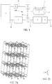
- the figure 2a represents the crystalline structure of a salt layer of MgCl 2 .
- the figure 2b represents an ammonia molecule.
- n can be 2 or 6.
- Figure 2c represents the crystalline structure of MgCl 2 (NH 3 ) 2 and the figure 2d the crystalline structure of MgCl 2 (NH 3 ) 6 .
- An ammonia storage structure must be able to perform several filling / emptying cycles during the life of the vehicle with which it is associated. These emptying / filling cycles give rise to ammonia phase changes.
- the emptying will be caused by raising the temperature of the structure, filling is ensured after connection of a chamber 8 to a feed circuit 200 of ammonia under pressure and via a cooling device of the assembly, for to evacuate the calories released during phase change of ammonia.
- the gas diffuses through the porous salt medium of the storage structure, from the grain of salt to the outlet of the enclosure, for example a cartridge, allowing the providing ammonia for injection into the exhaust.
- the ammonia is reintroduced into the system, diffuses into the porous medium created by the powdered salt and is absorbed within the grains of salt.
- the cycle of these transformations in time, or breathing of the material must be able to be done without deterioration of the capacity of storage and with reasonable durations. Heterogeneous compression gradients in the salt and sintering mechanisms can indeed deteriorate the storage structure.
- the additive may include expanded natural graphite which can be added to the salt prior to being compacted.
- the additive may comprise a metal powder, for example an aluminum powder.
- the salt can be previously intimately integrated with the additive, introduced into the chamber, and then compressed before being loaded with ammonia.
- a known technique for carrying out such a mixture consists in obtaining the link between the storage phase and the additive via a methanol bath. This process extrapolated to the scale of an automotive series production is complex and expensive investments, because of the intervention of an intermediate product, in this case methanol, and many additional phases of manufacture, such as the preparation of the methanol bath, the creation of the thermodynamic conditions of the mixture between the two products in the desired proportion, the drying of the assembly and the conditioning of the matrix thus obtained.
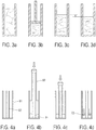
- the figure 3a represents a mixture of salt and powdered additive in a chamber.
- the figure 3b represents a compaction step of the mixture of salt and expanded powder additive in the enclosure.
- the figure 3c represents the salt mixed with the additive saturated with ammonia.
- the figure 3d represents the salt mixed with the additive after discharge of the ammonia.
- the mixture is however complex to achieve because the two components do not share the same density. The use of an unexpanded material would overcome this disadvantage, but would cause a decline in the quality of the storage matrix, in particular by lowering its thermal conductivity.
- the storage structure described below is intended to avoid the difficulties associated with storage in a structure consisting solely of salt or salt mixed with an additive.
- the ammonia storage structure comprises at least one layer comprising a pulverulent salt adapted to store and destock ammonia.
- the ammonia storage structure further comprises at least one layer of a thermally conductive material to increase heat transfer within the structure.
- the storage structure thus forms an ammonia storage structure comprising an alternation of at least one ammonia storage layer and at least one layer of a thermally conductive material.
- Alternation means an ammonia storage layer and a layer of a thermally conductive material.
- alternation is therefore meant that the structure comprises at least these two layers, or three superimposed layers, or more.
- the alternation may comprise a storage layer disposed between two layers of thermally conductive material, or a layer of thermally conductive material between two storage layers.
- the layers of thermally conductive material may be interposed between the storage layers, or the storage layers may be interposed between layers of thermally conductive material.
- the ammonia storage structure may for example comprise at least two layers comprising a pulverulent salt adapted to store and destock ammonia.
- the at least two layers of pulverulent salt are separated from each other by at least one layer of a thermally conductive material in order to increase heat transfer within the structure.
- the thermally conductive material is a material having a higher thermal conductivity than that of the salt with which it is associated. Its presence as an interlayer makes it possible to increase heat transfer within the storage structure.
- Such a structure also corresponds to an alternation. Alternation is also understood to mean a structure in which there is alternately a greater number of storage layers and layers of a thermally conductive material.
- the pulverulent salt is chosen from alkaline earth chlorides.
- the salt may consist of the following compounds: SrCl 2 , MgCl 2 , BaCl 2 , CaCl 2 , NaCl 2 .
- the salt layers preferably comprise salt grains whose particle size is between 1 and 1000 microns.
- the mass of thermally conductive material constitutes between 1% and 30% of the salt mass.
- the or each storage layer may be made of a compressed powdered salt, for example previously compressed or compressed while obtaining the storage structure.
- the storage layer may be made of an uncompressed powdered salt.
- the or each storage layer may be a rigid element.
- rigid element is meant element that can not essentially deform.
- the or each storage layer may not be a rigid element, for example a powder of an uncompressed salt or a more easily deformable element.
- the height of all the layers of a storage material is typically between 25% and 75%, more preferably for example between 50% and 75%, of the height of all the layers of a thermally conductive material, depending on the nature of the storage material and the thermally conductive material.
- each layer of a storage material is typically between 25% and 75%, more preferably for example between 50% and 75%, of the height of each layer of a thermally conductive material.
- Such intervals are particularly suitable in the case where the storage material comprises an alkaline earth salt and the thermally conductive material comprises expanded natural graphite, particularly in the case where the alkaline earth salt is sodium chloride. strontium or barium chloride.
- the thermally conductive material consists, for example, of a powder previously compressed to form the layer or layers of thermally conductive material.
- the layers of thermally conductive material consist for example of an uncompressed powder.
- the layers of thermally conductive material can form interlayers between which uncompressed salt powder is integrated.
- the salt layers can be formed of compressed or uncompressed rigid slabs.
- the salt layers may further comprise a mixture of powdered salt and an additive.
- the additive may be the thermally conductive material.
- the increase in the thermal conductivity of the assembly is achieved in part by the intermediate layers and partly by the presence of additive within the layer for storage.
- the number of intermediate layers of thermally conductive material is preferably between 1 and 30.
- the thermally conductive material may for example be expanded natural graphite compressed into interlayers.
- the thermally conductive material may comprise a metal powder, for example an aluminum powder.
- the thermally conductive material may be made of metal in solid form.
- the storage structure is or is intended to be disposed within an enclosure.
- ammonia gas under pressure in the chamber.
- the salt grains of the at least one storage layer absorb the ammonia. It is thus possible to at least partially fill the at least one gas storage layer with this ammonia.
- the layers of a storage material and the layers of a thermally conductive material can have various shapes, in particular sections of various shapes.
- the layers have for example substantially the same shape as the enclosure in which they must be placed or are placed.
- the layers may typically have a substantially cylindrical shape of round section, or oval, or rounded or rectangular or parallelepiped.
- the engine may be an internal combustion engine, for example a diesel engine, or a lean gasoline engine, such as a direct injection engine with a stratified mixture.
- a motor 1 is driven by an electronic computer 11. At the output of the engine, exhaust gases 12 are directed to a pollution control system 2.
- the pollution control system 2 may comprise an oxidation catalyst or a three-way catalyst.
- the pollution control system may further include a particulate filter.
- Ammonia 16 is injected into an exhaust circuit of the engine and mixed with the exhaust gas by means of an injection module 3 disposed for example downstream of the depollution element 2 to form a Ammonia / exhaust gas mixture 13.
- the ammonia / exhaust gas mixture 13 then passes through an SCR catalyst 4 which allows the reduction of NOx by ammonia.
- Complementary post-treatment elements may be positioned after the SCR catalyst.
- Complementary elements may include a particulate filter or an oxidation catalyst.
- the exhaust gas is thus in the form of exhausted exhaust gas 14 at the outlet of the complementary elements 5.
- the exhaust gas exhaust is then directed to an exhaust outlet.
- the exhaust comprises, arranged from upstream, engine side 1, downstream, on the outlet side, the depollution element 2, the injection module 3, the catalyst SCR 4, and the complementary elements 5.
- the system comprises an ammonia storage enclosure 8 containing a storage structure 7 that can be temperature-controlled by a heating device 9 or reheating.
- the heating device 9 comprises for example an electrical resistance or a heat exchanger supplied by a heat transfer fluid such as the engine coolant.
- the heating device 9 makes it possible, for example, to supply heat directly inside the enclosure 8. Alternatively, the heating device 9 makes it possible, for example, to transmit heat from outside the enclosure 8 to the inside the enclosure 8.
- the heating device 9 makes it possible to supply heat to the storage structure 7.
- the storage structure 7 comprises at least two layers of powdered salt, the at least two layers of powdered salt being separated from each other by at least one layer of a thermally conductive material.
- the layers of the storage structure 7 may have a symmetry of revolution of the same axis.
- the structure 7 can then have a recess along the axis of symmetry of revolution to allow storage and / or removal of ammonia at each salt layer.
- the structure 7 may comprise ammonia delivery channels from outside the enclosure 8 to the salt layers and / or in the opposite direction.
- the heating device 9 may comprise several heating modules (not shown), each heating module being adapted to heat a salt layer independently of the other salt layers.
- the storage enclosure 8 is connected to a device 6 for controlling the pressure of the chamber and for dosing ammonia to the injection module 3.
- This device 6 can be controlled by a dedicated electronic controller 10 connected to the calculator 11 electronic engine.
- the system thus comprises an ammonia feed circuit 200 comprising, upstream to downstream in the direction of flow of the ammonia, the storage enclosure 8, the device 6, and the injection module 3 in the exhaust.
- the device 6 can be directly controlled by the engine computer 11.
- the enclosure 8 has for example a symmetry of revolution.
- the enclosure 8 may then comprise a cylindrical outer wall 81 and an inner wall forming a tube 82 delimiting a central recess extending along the axis of symmetry of the enclosure 8.
- the method comprises a first step of depositing a first uncompressed powdered salt layer, for example in the annular zone situated between the outer wall 81 of the enclosure 8 and the wall of the tube 82.
- a second step of shaping the first salt layer by a plunger is described.
- This second step makes it possible to obtain a homogeneous first salt layer, of constant thickness, the shape of the surface of which is such that an intimate contact will be ensured with the layer of thermally conductive material subsequently formed.
- the first salt layer thus has, for example, a symmetry of revolution of the same axis as the enclosure 8.
- the thermally conductive material is for example a preformed block of expanded natural graphite.
- the layer of thermally conductive material 72 has, for example, the same properties of symmetry of revolution as the enclosure 8.
- the figure 4f represents the enclosure 8 after the deposition of a second layer of a thermally conductive material 74.
- the first three steps of the process can be repeated up to thirty times to obtain a stratified storage structure.
- rigid cakes of salt can be prepared in advance by compression or by the use of a binder.
- the layers of salt and expanded natural graphite are then implanted by successive stacks of rigid slabs.
- the enclosure 8 is empty.
- the enclosure 8 has for example a symmetry of revolution.
- the enclosure 8 may then comprise a cylindrical outer wall 81 and an inner wall forming a tube 82 delimiting a central recess extending along the axis of symmetry of the enclosure 8.
- the method comprises a first step of depositing a first layer of a storage material.
- the first layer is typically a rigid slab of compressed powdered salt.
- the first layer of a storage material is typically deposited in an annular zone located between the outer wall 81 of the enclosure 8 and the wall of the tube 82.
- the method comprises a second step of depositing a first layer of a thermally conductive material on the first layer of a storage material.
- the thermally conductive material is for example an expandable natural graphite stratum.
- the layer of thermally conductive material has for example the same properties of symmetry of revolution as the enclosure 8.
- the method comprises a third step of depositing a second layer of a storage material, similar to that of the first step, on the first layer of a thermally conductive material.
- the first two steps of the process can be repeated up to thirty times to obtain a stratified storage structure.
- some of the layers may be preassembled outside the enclosure 8.
- a method of making the storage structure 7 described according to a third exemplary embodiment, using such rigid wafers is here described.
- the method includes a first step of providing a first layer of a storage material and a first layer of a thermally conductive material.
- the first layer is typically a rigid slab of compressed powdered salt.
- the thermally conductive material is for example an expandable natural graphite stratum.
- the method includes a second step of pre-assembling the first layer of a storage material with the first layer of a thermally conductive material.
- pre-assembly means an assembly, typically partial, made upstream of the arrangement in the enclosure described above, so that the layers are integral with one another.
- the layers, or given groups of layers are for example pre-assembled together by means of an adhesive.
- the layers are for example assembled together by compression of the layers against each other so that they adhere to each other and / or interpenetrate in the vicinity of their interface .
- the method may then comprise one or more successive third stages of pre-assembly integral with one or more layers of a storage material and / or one or more layers of a material made of a thermally conductive material at the pre-assembly. obtained in the preceding steps to form a pre-assembly having an alternation as described above.
- the method may comprise a fourth step of producing a storage structure in an enclosure according to one of the methods described above, further comprising a step of depositing the pre-assembly thus formed typically outside the enclosure, as a part of the storage structure in formation.
- Such a pre-assembly facilitates the rear mounting of the storage structure in the storage enclosure.
- pre-assembly allows standardization of the pre-assemblies as elements of the matrix to be mounted to form the structure in the enclosure. It is thus possible to obtain storage structures with more homogeneous and therefore more predictable properties, which allows better control during their subsequent use.
- a matching heat conduction block can be associated with a storage salt block, thereby optimizing the operating conditions in each of the pre-assembled groups.
- the or each storage layer and the or each layer of thermally conductive material are assembled or formed in the enclosure to obtain the storage structure in the absence ammonia.
- the salt layers do not contain ammonia during the previously described steps.
- the process may therefore comprise a step subsequent to the preceding steps, in which the storage structure thus formed is at least partially saturated with ammonia.
- the or each storage layer and the or each layer of thermally conductive material are formed and assembled so that a gap remains between the or each layer of thermally conductive material and the inner face of the wall of the enclosure.
- the figure 4h represents a complete storage structure 7 saturated with ammonia in an enclosure 8 closed in operation.
- the or each layer of thermally conductive material may be made so as to be elastically deformable. It can thus be for example be formed of expanded natural graphite pre-compressed.
- the or each storage layer increases in volume and the at least one layer of a thermally conductive material undergoes forces that deforms.
- the structure and the enclosure may in particular be dimensioned so that this deformation does not imply a significant change in the density of the or each layer in a thermally conductive material, as long as a free space in the enclosure allows a change of constant density form.
- the or each layer of thermally conductive material can thus be deformed until it comes into contact with the inner wall of the enclosure in the play zone, for example the peripheral wall. This allows in particular to ensure a satisfactory circulation of the heat provided by the heating device to the or each layer of thermally conductive material.
- the thickness of the or each layer of a thermally conductive material may decrease and its diameter increase without change in density, that is to say without changing the total volume occupied by the layer.
- the structure can be sized so that when the entire volume of the interior of the enclosure is occupied by the storage structure, that is to say when no more free volume of the enclosure is accessible to no layer of a thermally conductive material, the or each storage layer is not yet saturated with ammonia. Further filling of the or each storage layer involves an additional volume increase of the or each storage layer. This increase in volume is then at least partially compensated and / or the resulting forces at least partially absorbed by compression of the or each thermally conductive material, whose density then increases.
- natural expanded natural graphite has a density about one hundred times lower than non-porous non-porous graphite.
- the at least one layer of a thermally conductive material is formed of pre-compressed expanded natural graphite, for example in the form of a rigid slab, the or each layer of thermally conductive material may have a density still ten times greater than the unexpanded graphite non-porous. Its theoretical compression capacity is therefore a factor of ten.
- the storage structure can be made in such a way that the different layers are held in mutual contact even when the structure is not saturated, or is almost empty of ammonia. This results in better thermal conductivity. Moreover, the fact that the elements of the structure are maintained prevents them from moving and wear out in advance by friction or mechanical shock.
- Such a storage structure has the advantage of nevertheless limiting the forces experienced by the enclosure within which the storage structure is disposed. Indeed, the efforts resulting from the increase in the volume of the or each storage layer are absorbed by the or each layer of thermally conductive material, which changes shape to constant density as long as a game space can be occupied, then that is compressed, with an increase in density, as soon as any accessible play space is occupied.
- the layers of the storage structure may be formed of a stack of disks, or patties, alternated.
- the enclosure may be of generally cylindrical or conical shape or having any cross section, for example square or oval.
- the enclosure may have a general shape pierced from side to side along a given axis.
- the slabs In the case of a conical enclosure or a form with a variable section, the slabs have diameters of variable dimensions.
- the structure may have an alternation of at least one storage layer disk and at least one layer disk of a thermally conductive material.
- the disks may be provided such that the thickness of the vacuum storage layer is at least two times greater than the thickness of a layer of adjacent thermally conductive vacuum material.
- the discs can be provided so that the clearance between the edge of the layer of thermally conductive material and the inner face of the wall of the enclosure which contains the storage structure, that is to say the space on either side of the layer, between 2% and 30%, more preferably between 5% and 16%, for example, of the transverse diameter of the layer (or equivalent main length in the case of a particular contour structure) when the storage structure is empty of ammonia.
- a first step layers of thermally conductive material are prepared.
- a preliminary compression step at given dimensions, in particular at a thickness given and / or given section, can provide such layers at a desired density.
- layers of storage material are prepared. These layers may be prepared by compression of a powder comprising a powdery salt as described above. This compression can be performed so as to obtain layers of given dimensions, in particular with a given thickness and / or a given section.
- the layers of storage material and the layers of thermally conductive material are placed in the enclosure so as to form the storage structure in the form of a stack having an alternation of these layers.
- the layers or groups of layers can be stacked alternately outside the enclosure, the layers adhering to each other to form one or more self-supporting solid assemblies. This or these sets are then placed inside the enclosure.
- each layer of thermally conductive material 52 is dimensioned with respect to the enclosure to present a clearance 53 between said layer and the wall 54 of the enclosure when the structure n ' is not saturated with ammonia, so that an increase in the volume of an adjacent storage layer 51 during an ammonia filling is compensated in an initial filling phase by a change in the shape of the layer of thermally material conductor 52 to occupy a free space resulting from the game.
- the layer of thermally conductive material may optionally compress to absorb the subsequent increase in volume.
- the layer of thermally conductive material in intimate contact with both the wall of the enclosure and the layer of storage material, provides excellent heat transfer.
Landscapes
- Chemical & Material Sciences (AREA)
- Engineering & Computer Science (AREA)
- Chemical Kinetics & Catalysis (AREA)
- Mechanical Engineering (AREA)
- Organic Chemistry (AREA)
- Combustion & Propulsion (AREA)
- Toxicology (AREA)
- General Engineering & Computer Science (AREA)
- Health & Medical Sciences (AREA)
- Inorganic Chemistry (AREA)
- Exhaust Gas After Treatment (AREA)
- Filling Or Discharging Of Gas Storage Vessels (AREA)
- Laminated Bodies (AREA)
Claims (15)
- Struktur zur Lagerung von Ammoniak (7), die eine Abwechslung umfasst:zumindest eine Ammoniaklagerschicht (71, 73), undzumindest eine Schicht aus einem wärmeleitenden Material (72) mit höherer Wärmeleitfähigkeit als diejenige der Lagerschicht (71, 73), wobei die oder jede Schicht aus wärmeleitendem Material (72) dazu bestimmt ist, die Wärmeübergänge innerhalb der Struktur zu erhöhen,dadurch gekennzeichnet, dass jede Schicht eine vollständige gegenseitige Trennung zwischen den beiden benachbarten Schichten gewährleistet.
- Struktur nach Anspruch 1, dadurch gekennzeichnet, dass die oder jede Schicht aus wärmeleitendem Material (72) aus einem zuvor verdichteten Pulver besteht.
- System zur Lagerung und Entnahme von Ammoniak eines Fahrzeugs mit einem Speichergehäuse (8), dadurch gekennzeichnet, dass das Speichergehäuse (8) eine Lagerstruktur (7) nach einem der Ansprüche 1 oder 2 aufweist.
- Lagersystem nach Anspruch 3, dadurch gekennzeichnet, dass die oder jede Schicht aus wärmeleitendem Material relativ zum Gehäuse so dimensioniert ist, dass sie ein Spiel zwischen der Schicht und der Gehäusewand hat, wenn die Struktur nicht mit Ammoniak gesättigt ist, so dass eine Volumenzunahme der mindestens einen Lagerschicht durch Ammoniaklagerung in einer Anfangsphase der Befüllung durch eine Änderung der Form der Schicht aus wärmeleitendem Material kompensiert wird, um einen aus dem Spiel resultierenden Freiraum einzunehmen.
- Lagersystem nach Anspruch 4, dadurch gekennzeichnet, dass sich das Spiel zwischen einer Seitenwand des Gehäuses und einer Seitenwand der wärmeleitenden Materialschicht befindet.
- Lagersystem nach Anspruch 5, dadurch gekennzeichnet, dass das Spiel zwischen 2 % und 30 % des Querdurchmessers der wärmeleitenden Materialschicht beträgt.
- Lagersystem nach einem der Ansprüche 3 bis 6, dadurch gekennzeichnet, dass die Lagerstruktur so aufgebaut ist, dass die oder jede Schicht aus wärmeleitendem Material in einer Endphase der Befüllung zur Verdichtung geeignet ist.
- Lagersystem nach einem der Ansprüche 3 bis 7, dadurch gekennzeichnet, dass die Schichten der Struktur (7) eine Rotationssymmetrie der gleichen Achse aufweisen, und dass die Struktur (7) entlang der Rotationssymmetrieachse eine Ausnehmung aufweist, um die Lagerung und/oder die Entnahme von Ammoniak an jeder Lagerschicht (71, 73) zu ermöglichen.
- Lagersystem nach einem der Ansprüche 3 bis 8, dadurch gekennzeichnet, dass es eine Heizvorrichtung (9) der Lagerstruktur zur Entnahme von in der Struktur (7) gelagertem Ammoniak umfasst, wobei die Heizvorrichtung (9) mehrere Heizmodule umfasst, wobei jedes Heizmodul geeignet ist, eine Lagerschicht (71, 73) unabhängig von anderen Lagerschichten zu erhitzen.
- Selektives katalytisches Reduktionssystem für Abgase von Verbrennungsmotoren, dadurch gekennzeichnet, dass es ein Ammoniaklagersystem nach einem der Ansprüche 3 bis 9 und ein Modul zum Einspritzen von Ammoniak in die Abgase umfasst.
- Verfahren zur Herstellung einer Ammoniak-Lagerstruktur nach einem der Ansprüche 1 oder 2, wobei das Verfahren die folgenden Schritte umfasst:Ablagerung einer Lagerschicht umfassend ein unverdichtetes oder vorher verdichtetes Salz (71),Ablagerung einer Schicht aus einem wärmeleitenden Material (72) mit einer höheren Wärmeleitfähigkeit als diejenige der Lagerschicht (71), bestehend aus einem zuvor verdichteten Pulver,wobei diese beiden Schritte wiederholt werden, um eine Struktur aufzubauen, die aus einem Wechsel von (einer) Lagerschicht(en) und (einer) wärmeleitenden Zwischenschicht(en) besteht.
- Verfahren nach Anspruch 11, wobei die Ablagerungsschritte in einem Speichergehäuse (8) durchgeführt werden.
- Verfahren nach Anspruch 12, wobei die erste Salzschicht pulverförmig ist, wobei das Verfahren das Einbringen des pulverförmigen Salzes in das Gehäuse zur Bildung einer Schicht und das Formen dieser Schicht durch einen Taucher umfasst.
- Verfahren nach Anspruch 12, wobei die Lagerschicht und die Schicht aus einem wärmeleitenden Material vormontiert werden, wobei die beiden Schichten dann gleichzeitig im Gehäuse abgelagert werden.
- Verfahren nach Anspruch 14, wobei die Vormontage durch Kleben und/oder Verdichten der Schichten aneinander erfolgt.
Priority Applications (1)
| Application Number | Priority Date | Filing Date | Title |
|---|---|---|---|
| EP13762413.6A EP2882686B1 (de) | 2012-08-09 | 2013-08-09 | Struktur zur lagerung von ammoniak und entsprechende systeme und verfahren |
Applications Claiming Priority (3)
| Application Number | Priority Date | Filing Date | Title |
|---|---|---|---|
| EP12305993.3A EP2695859B1 (de) | 2012-08-09 | 2012-08-09 | Struktur zur Lagerung von Ammoniak und entsprechende Systeme und Verfahren |
| PCT/EP2013/066768 WO2014023840A1 (fr) | 2012-08-09 | 2013-08-09 | Structure de stockage d'ammoniac et systemes et procede associes |
| EP13762413.6A EP2882686B1 (de) | 2012-08-09 | 2013-08-09 | Struktur zur lagerung von ammoniak und entsprechende systeme und verfahren |
Publications (2)
| Publication Number | Publication Date |
|---|---|
| EP2882686A1 EP2882686A1 (de) | 2015-06-17 |
| EP2882686B1 true EP2882686B1 (de) | 2018-09-19 |
Family
ID=46968104
Family Applications (2)
| Application Number | Title | Priority Date | Filing Date |
|---|---|---|---|
| EP12305993.3A Not-in-force EP2695859B1 (de) | 2012-08-09 | 2012-08-09 | Struktur zur Lagerung von Ammoniak und entsprechende Systeme und Verfahren |
| EP13762413.6A Not-in-force EP2882686B1 (de) | 2012-08-09 | 2013-08-09 | Struktur zur lagerung von ammoniak und entsprechende systeme und verfahren |
Family Applications Before (1)
| Application Number | Title | Priority Date | Filing Date |
|---|---|---|---|
| EP12305993.3A Not-in-force EP2695859B1 (de) | 2012-08-09 | 2012-08-09 | Struktur zur Lagerung von Ammoniak und entsprechende Systeme und Verfahren |
Country Status (7)
| Country | Link |
|---|---|
| US (1) | US9878917B2 (de) |
| EP (2) | EP2695859B1 (de) |
| JP (1) | JP6250669B2 (de) |
| KR (1) | KR20150040334A (de) |
| CN (1) | CN104703917B (de) |
| IN (1) | IN2015DN01016A (de) |
| WO (1) | WO2014023840A1 (de) |
Families Citing this family (5)
| Publication number | Priority date | Publication date | Assignee | Title |
|---|---|---|---|---|
| FR3043163B1 (fr) * | 2015-10-29 | 2018-05-18 | Plastic Omnium Advanced Innovation And Research | Conteneur pour stockage d'ammoniac. |
| FR3061035B1 (fr) * | 2016-12-28 | 2019-05-31 | Faurecia Systemes D'echappement | Procedes de fabrication d'un materiau et d'une unite de stockage d'un gaz |
| GB2567205B (en) * | 2017-10-06 | 2021-06-23 | Siemens Plc | Uses of an absorbent, and methods and apparatuses relating thereto |
| GB2567211B (en) * | 2017-10-06 | 2021-07-07 | Siemens Plc | Uses of an absorbent, and methods and apparatuses relating thereto |
| FR3084722A1 (fr) * | 2018-07-31 | 2020-02-07 | Aaqius & Aaqius Sa | Dispositif de stockage de gaz par sorption |
Family Cites Families (16)
| Publication number | Priority date | Publication date | Assignee | Title |
|---|---|---|---|---|
| US4134491A (en) | 1978-02-24 | 1979-01-16 | The International Nickel Company, Inc. | Hydride storage containment |
| DE3338879C2 (de) | 1983-10-24 | 1986-11-13 | Mannesmann AG, 4000 Düsseldorf | Druckgasbehälter |
| AU627295B2 (en) | 1989-03-08 | 1992-08-20 | Rocky Research | Method and apparatus for achieving high reaction rates in solid-gas reactor systems |
| JPH06158194A (ja) | 1992-11-20 | 1994-06-07 | Toyota Motor Corp | 水素吸蔵合金材料 |
| WO2006012903A2 (en) * | 2004-08-03 | 2006-02-09 | Amminex A/S | A solid ammonia storage and delivery material |
| ES2355274T3 (es) * | 2007-03-30 | 2011-03-24 | Amminex A/S | Sistema para almacenar amoniaco y liberar amoniaco de un material de almacenamiento y procedimiento para almacenar y liberar amoniaco. |
| DE102008002338A1 (de) * | 2008-06-10 | 2009-12-17 | Robert Bosch Gmbh | Vorrichtung zur Freisetzung von Ammoniak |
| US8916493B2 (en) * | 2008-09-08 | 2014-12-23 | Amminex Emissions Technology A/S | Additives for highly compacted ammonia storage materials |
| MX2012003766A (es) * | 2009-09-30 | 2012-06-12 | Amminex As | Estructuras conductoras de calor conectadas en sistemas de almacenamiento de amoniaco solido. |
| US8951437B2 (en) * | 2009-09-30 | 2015-02-10 | Amminex Emissions Technology A/S | Connected heat conducting structures in solid ammonia storage systems |
| US20130011316A1 (en) * | 2010-03-24 | 2013-01-10 | Mella Ramon A | Strontium chloride expansive disks and compression welded cartridge and method |
| JP2011236105A (ja) * | 2010-05-13 | 2011-11-24 | Toyota Industries Corp | アンモニア放出装置、アンモニア放出方法及び排気ガス浄化装置 |
| FR2962122B1 (fr) * | 2010-07-01 | 2012-08-10 | Faurecia Sys Echappement | Procede de fabrication d'une cartouche de stockage d'ammoniaque, notamment pour systeme d'echappement de gaz de vehicule automobile |
| EP2428490B1 (de) * | 2010-09-10 | 2014-10-22 | Aaqius & Aaqius S.A. | Verfahren zur Reduzierung der Menge an Stickoxiden (NOx) in Abgasen von Kraftfahrzeugen |
| WO2013082078A1 (en) * | 2011-12-02 | 2013-06-06 | Cummins Inc. | Solid storage media charging with ammonia for use in selective catalytic reduction |
| FR2991712B1 (fr) * | 2012-06-06 | 2014-07-04 | Faurecia Sys Echappement | Dispositif de generation d'ammoniac |
-
2012
- 2012-08-09 EP EP12305993.3A patent/EP2695859B1/de not_active Not-in-force
-
2013
- 2013-08-09 CN CN201380051992.4A patent/CN104703917B/zh not_active Expired - Fee Related
- 2013-08-09 IN IN1016DEN2015 patent/IN2015DN01016A/en unknown
- 2013-08-09 JP JP2015525908A patent/JP6250669B2/ja not_active Expired - Fee Related
- 2013-08-09 EP EP13762413.6A patent/EP2882686B1/de not_active Not-in-force
- 2013-08-09 US US14/419,928 patent/US9878917B2/en not_active Expired - Fee Related
- 2013-08-09 KR KR20157005558A patent/KR20150040334A/ko not_active Ceased
- 2013-08-09 WO PCT/EP2013/066768 patent/WO2014023840A1/fr not_active Ceased
Non-Patent Citations (1)
| Title |
|---|
| None * |
Also Published As
| Publication number | Publication date |
|---|---|
| WO2014023840A1 (fr) | 2014-02-13 |
| IN2015DN01016A (de) | 2015-06-26 |
| US9878917B2 (en) | 2018-01-30 |
| EP2695859A1 (de) | 2014-02-12 |
| CN104703917A (zh) | 2015-06-10 |
| CN104703917B (zh) | 2018-03-20 |
| KR20150040334A (ko) | 2015-04-14 |
| JP6250669B2 (ja) | 2017-12-20 |
| JP2015525733A (ja) | 2015-09-07 |
| EP2882686A1 (de) | 2015-06-17 |
| US20150183648A1 (en) | 2015-07-02 |
| EP2695859B1 (de) | 2015-09-16 |
Similar Documents
| Publication | Publication Date | Title |
|---|---|---|
| EP2890875B1 (de) | Ammoniakspeichereinheit und damit verknüpfte struktur und system | |
| EP2428490B1 (de) | Verfahren zur Reduzierung der Menge an Stickoxiden (NOx) in Abgasen von Kraftfahrzeugen | |
| EP2882686B1 (de) | Struktur zur lagerung von ammoniak und entsprechende systeme und verfahren | |
| FR3004440B1 (fr) | Structure de stockage d'ammoniac et systemes associes | |
| EP3230563B1 (de) | Abgasnachbehandlungseinrichtung für eine verbrennungskraftmaschine | |
| EP2882685B1 (de) | System zur lagerung und abgabe von gasförmigem ammoniak | |
| FR2944052A1 (fr) | Structure de filtration d'un gaz et de reduction des nox. | |
| FR3004439B1 (fr) | Structure de stockage d'ammoniac et systemes associes | |
| EP2412946B1 (de) | Verfahren zur Reduzierung der Menge an Stickoxiden (NOx) in Abgasen von Kraftfahrzeugen | |
| EP3153677B1 (de) | Vorrichtung zur nachbehandlung von abgasen eines verbrennungsmotors | |
| FR3004438B1 (fr) | Structure de stockage d'ammoniac et systemes associes | |
| EP2749746B1 (de) | Lagereinheit für Ammoniak, entsprechende Struktur und entsprechendes System | |
| FR3081921A1 (fr) | Ligne d’echappement de moteur thermique comprenant un element de chauffage amont | |
| FR3062680A1 (fr) | Dispositif de post-traitement des gaz d’echappement d’un moteur thermique | |
| FR3061035A1 (fr) | Procedes de fabrication d'un materiau et d'une unite de stockage d'un gaz | |
| EP2990097A1 (de) | Katalysierter partikelfilter | |
| FR3120094A1 (fr) | Ligne d’echappement de moteur thermique comprenant des elements de chauffage | |
| FR3042218A1 (fr) | Filtre a particules |
Legal Events
| Date | Code | Title | Description |
|---|---|---|---|
| PUAI | Public reference made under article 153(3) epc to a published international application that has entered the european phase |
Free format text: ORIGINAL CODE: 0009012 |
|
| 17P | Request for examination filed |
Effective date: 20150306 |
|
| AK | Designated contracting states |
Kind code of ref document: A1 Designated state(s): AL AT BE BG CH CY CZ DE DK EE ES FI FR GB GR HR HU IE IS IT LI LT LU LV MC MK MT NL NO PL PT RO RS SE SI SK SM TR |
|
| AX | Request for extension of the european patent |
Extension state: BA ME |
|
| DAX | Request for extension of the european patent (deleted) | ||
| STAA | Information on the status of an ep patent application or granted ep patent |
Free format text: STATUS: EXAMINATION IS IN PROGRESS |
|
| 17Q | First examination report despatched |
Effective date: 20170922 |
|
| RIC1 | Information provided on ipc code assigned before grant |
Ipc: F01N 3/24 20060101ALI20180125BHEP Ipc: C01C 1/00 20060101AFI20180125BHEP Ipc: F01N 3/20 20060101ALI20180125BHEP |
|
| GRAP | Despatch of communication of intention to grant a patent |
Free format text: ORIGINAL CODE: EPIDOSNIGR1 |
|
| STAA | Information on the status of an ep patent application or granted ep patent |
Free format text: STATUS: GRANT OF PATENT IS INTENDED |
|
| INTG | Intention to grant announced |
Effective date: 20180321 |
|
| GRAS | Grant fee paid |
Free format text: ORIGINAL CODE: EPIDOSNIGR3 |
|
| GRAA | (expected) grant |
Free format text: ORIGINAL CODE: 0009210 |
|
| STAA | Information on the status of an ep patent application or granted ep patent |
Free format text: STATUS: THE PATENT HAS BEEN GRANTED |
|
| AK | Designated contracting states |
Kind code of ref document: B1 Designated state(s): AL AT BE BG CH CY CZ DE DK EE ES FI FR GB GR HR HU IE IS IT LI LT LU LV MC MK MT NL NO PL PT RO RS SE SI SK SM TR |
|
| REG | Reference to a national code |
Ref country code: GB Ref legal event code: FG4D Free format text: NOT ENGLISH |
|
| REG | Reference to a national code |
Ref country code: CH Ref legal event code: EP |
|
| REG | Reference to a national code |
Ref country code: AT Ref legal event code: REF Ref document number: 1043025 Country of ref document: AT Kind code of ref document: T Effective date: 20181015 |
|
| REG | Reference to a national code |
Ref country code: IE Ref legal event code: FG4D Free format text: LANGUAGE OF EP DOCUMENT: FRENCH |
|
| REG | Reference to a national code |
Ref country code: DE Ref legal event code: R096 Ref document number: 602013043913 Country of ref document: DE |
|
| REG | Reference to a national code |
Ref country code: NL Ref legal event code: MP Effective date: 20180919 |
|
| PG25 | Lapsed in a contracting state [announced via postgrant information from national office to epo] |
Ref country code: LT Free format text: LAPSE BECAUSE OF FAILURE TO SUBMIT A TRANSLATION OF THE DESCRIPTION OR TO PAY THE FEE WITHIN THE PRESCRIBED TIME-LIMIT Effective date: 20180919 Ref country code: SE Free format text: LAPSE BECAUSE OF FAILURE TO SUBMIT A TRANSLATION OF THE DESCRIPTION OR TO PAY THE FEE WITHIN THE PRESCRIBED TIME-LIMIT Effective date: 20180919 Ref country code: FI Free format text: LAPSE BECAUSE OF FAILURE TO SUBMIT A TRANSLATION OF THE DESCRIPTION OR TO PAY THE FEE WITHIN THE PRESCRIBED TIME-LIMIT Effective date: 20180919 Ref country code: RS Free format text: LAPSE BECAUSE OF FAILURE TO SUBMIT A TRANSLATION OF THE DESCRIPTION OR TO PAY THE FEE WITHIN THE PRESCRIBED TIME-LIMIT Effective date: 20180919 Ref country code: NO Free format text: LAPSE BECAUSE OF FAILURE TO SUBMIT A TRANSLATION OF THE DESCRIPTION OR TO PAY THE FEE WITHIN THE PRESCRIBED TIME-LIMIT Effective date: 20181219 Ref country code: BG Free format text: LAPSE BECAUSE OF FAILURE TO SUBMIT A TRANSLATION OF THE DESCRIPTION OR TO PAY THE FEE WITHIN THE PRESCRIBED TIME-LIMIT Effective date: 20181219 Ref country code: GR Free format text: LAPSE BECAUSE OF FAILURE TO SUBMIT A TRANSLATION OF THE DESCRIPTION OR TO PAY THE FEE WITHIN THE PRESCRIBED TIME-LIMIT Effective date: 20181220 |
|
| REG | Reference to a national code |
Ref country code: LT Ref legal event code: MG4D |
|
| PG25 | Lapsed in a contracting state [announced via postgrant information from national office to epo] |
Ref country code: HR Free format text: LAPSE BECAUSE OF FAILURE TO SUBMIT A TRANSLATION OF THE DESCRIPTION OR TO PAY THE FEE WITHIN THE PRESCRIBED TIME-LIMIT Effective date: 20180919 Ref country code: LV Free format text: LAPSE BECAUSE OF FAILURE TO SUBMIT A TRANSLATION OF THE DESCRIPTION OR TO PAY THE FEE WITHIN THE PRESCRIBED TIME-LIMIT Effective date: 20180919 Ref country code: AL Free format text: LAPSE BECAUSE OF FAILURE TO SUBMIT A TRANSLATION OF THE DESCRIPTION OR TO PAY THE FEE WITHIN THE PRESCRIBED TIME-LIMIT Effective date: 20180919 |
|
| REG | Reference to a national code |
Ref country code: AT Ref legal event code: MK05 Ref document number: 1043025 Country of ref document: AT Kind code of ref document: T Effective date: 20180919 |
|
| PG25 | Lapsed in a contracting state [announced via postgrant information from national office to epo] |
Ref country code: CZ Free format text: LAPSE BECAUSE OF FAILURE TO SUBMIT A TRANSLATION OF THE DESCRIPTION OR TO PAY THE FEE WITHIN THE PRESCRIBED TIME-LIMIT Effective date: 20180919 Ref country code: RO Free format text: LAPSE BECAUSE OF FAILURE TO SUBMIT A TRANSLATION OF THE DESCRIPTION OR TO PAY THE FEE WITHIN THE PRESCRIBED TIME-LIMIT Effective date: 20180919 Ref country code: ES Free format text: LAPSE BECAUSE OF FAILURE TO SUBMIT A TRANSLATION OF THE DESCRIPTION OR TO PAY THE FEE WITHIN THE PRESCRIBED TIME-LIMIT Effective date: 20180919 Ref country code: IS Free format text: LAPSE BECAUSE OF FAILURE TO SUBMIT A TRANSLATION OF THE DESCRIPTION OR TO PAY THE FEE WITHIN THE PRESCRIBED TIME-LIMIT Effective date: 20190119 Ref country code: PL Free format text: LAPSE BECAUSE OF FAILURE TO SUBMIT A TRANSLATION OF THE DESCRIPTION OR TO PAY THE FEE WITHIN THE PRESCRIBED TIME-LIMIT Effective date: 20180919 Ref country code: NL Free format text: LAPSE BECAUSE OF FAILURE TO SUBMIT A TRANSLATION OF THE DESCRIPTION OR TO PAY THE FEE WITHIN THE PRESCRIBED TIME-LIMIT Effective date: 20180919 Ref country code: EE Free format text: LAPSE BECAUSE OF FAILURE TO SUBMIT A TRANSLATION OF THE DESCRIPTION OR TO PAY THE FEE WITHIN THE PRESCRIBED TIME-LIMIT Effective date: 20180919 Ref country code: AT Free format text: LAPSE BECAUSE OF FAILURE TO SUBMIT A TRANSLATION OF THE DESCRIPTION OR TO PAY THE FEE WITHIN THE PRESCRIBED TIME-LIMIT Effective date: 20180919 Ref country code: IT Free format text: LAPSE BECAUSE OF FAILURE TO SUBMIT A TRANSLATION OF THE DESCRIPTION OR TO PAY THE FEE WITHIN THE PRESCRIBED TIME-LIMIT Effective date: 20180919 |
|
| PG25 | Lapsed in a contracting state [announced via postgrant information from national office to epo] |
Ref country code: SM Free format text: LAPSE BECAUSE OF FAILURE TO SUBMIT A TRANSLATION OF THE DESCRIPTION OR TO PAY THE FEE WITHIN THE PRESCRIBED TIME-LIMIT Effective date: 20180919 Ref country code: SK Free format text: LAPSE BECAUSE OF FAILURE TO SUBMIT A TRANSLATION OF THE DESCRIPTION OR TO PAY THE FEE WITHIN THE PRESCRIBED TIME-LIMIT Effective date: 20180919 Ref country code: PT Free format text: LAPSE BECAUSE OF FAILURE TO SUBMIT A TRANSLATION OF THE DESCRIPTION OR TO PAY THE FEE WITHIN THE PRESCRIBED TIME-LIMIT Effective date: 20190119 |
|
| REG | Reference to a national code |
Ref country code: DE Ref legal event code: R097 Ref document number: 602013043913 Country of ref document: DE |
|
| PLBE | No opposition filed within time limit |
Free format text: ORIGINAL CODE: 0009261 |
|
| STAA | Information on the status of an ep patent application or granted ep patent |
Free format text: STATUS: NO OPPOSITION FILED WITHIN TIME LIMIT |
|
| PG25 | Lapsed in a contracting state [announced via postgrant information from national office to epo] |
Ref country code: DK Free format text: LAPSE BECAUSE OF FAILURE TO SUBMIT A TRANSLATION OF THE DESCRIPTION OR TO PAY THE FEE WITHIN THE PRESCRIBED TIME-LIMIT Effective date: 20180919 |
|
| 26N | No opposition filed |
Effective date: 20190620 |
|
| PG25 | Lapsed in a contracting state [announced via postgrant information from national office to epo] |
Ref country code: SI Free format text: LAPSE BECAUSE OF FAILURE TO SUBMIT A TRANSLATION OF THE DESCRIPTION OR TO PAY THE FEE WITHIN THE PRESCRIBED TIME-LIMIT Effective date: 20180919 |
|
| PG25 | Lapsed in a contracting state [announced via postgrant information from national office to epo] |
Ref country code: TR Free format text: LAPSE BECAUSE OF FAILURE TO SUBMIT A TRANSLATION OF THE DESCRIPTION OR TO PAY THE FEE WITHIN THE PRESCRIBED TIME-LIMIT Effective date: 20180919 |
|
| GBPC | Gb: european patent ceased through non-payment of renewal fee |
Effective date: 20190809 |
|
| PG25 | Lapsed in a contracting state [announced via postgrant information from national office to epo] |
Ref country code: LU Free format text: LAPSE BECAUSE OF NON-PAYMENT OF DUE FEES Effective date: 20190809 Ref country code: MC Free format text: LAPSE BECAUSE OF FAILURE TO SUBMIT A TRANSLATION OF THE DESCRIPTION OR TO PAY THE FEE WITHIN THE PRESCRIBED TIME-LIMIT Effective date: 20180919 Ref country code: LI Free format text: LAPSE BECAUSE OF NON-PAYMENT OF DUE FEES Effective date: 20190831 Ref country code: CH Free format text: LAPSE BECAUSE OF NON-PAYMENT OF DUE FEES Effective date: 20190831 |
|
| REG | Reference to a national code |
Ref country code: BE Ref legal event code: MM Effective date: 20190831 |
|
| PG25 | Lapsed in a contracting state [announced via postgrant information from national office to epo] |
Ref country code: IE Free format text: LAPSE BECAUSE OF NON-PAYMENT OF DUE FEES Effective date: 20190809 |
|
| PG25 | Lapsed in a contracting state [announced via postgrant information from national office to epo] |
Ref country code: GB Free format text: LAPSE BECAUSE OF NON-PAYMENT OF DUE FEES Effective date: 20190809 Ref country code: BE Free format text: LAPSE BECAUSE OF NON-PAYMENT OF DUE FEES Effective date: 20190831 |
|
| PG25 | Lapsed in a contracting state [announced via postgrant information from national office to epo] |
Ref country code: CY Free format text: LAPSE BECAUSE OF FAILURE TO SUBMIT A TRANSLATION OF THE DESCRIPTION OR TO PAY THE FEE WITHIN THE PRESCRIBED TIME-LIMIT Effective date: 20180919 |
|
| PG25 | Lapsed in a contracting state [announced via postgrant information from national office to epo] |
Ref country code: MT Free format text: LAPSE BECAUSE OF FAILURE TO SUBMIT A TRANSLATION OF THE DESCRIPTION OR TO PAY THE FEE WITHIN THE PRESCRIBED TIME-LIMIT Effective date: 20180919 Ref country code: HU Free format text: LAPSE BECAUSE OF FAILURE TO SUBMIT A TRANSLATION OF THE DESCRIPTION OR TO PAY THE FEE WITHIN THE PRESCRIBED TIME-LIMIT; INVALID AB INITIO Effective date: 20130809 |
|
| PGFP | Annual fee paid to national office [announced via postgrant information from national office to epo] |
Ref country code: FR Payment date: 20210819 Year of fee payment: 9 |
|
| PGFP | Annual fee paid to national office [announced via postgrant information from national office to epo] |
Ref country code: DE Payment date: 20210819 Year of fee payment: 9 |
|
| PG25 | Lapsed in a contracting state [announced via postgrant information from national office to epo] |
Ref country code: MK Free format text: LAPSE BECAUSE OF FAILURE TO SUBMIT A TRANSLATION OF THE DESCRIPTION OR TO PAY THE FEE WITHIN THE PRESCRIBED TIME-LIMIT Effective date: 20180919 |
|
| REG | Reference to a national code |
Ref country code: DE Ref legal event code: R119 Ref document number: 602013043913 Country of ref document: DE |
|
| PG25 | Lapsed in a contracting state [announced via postgrant information from national office to epo] |
Ref country code: FR Free format text: LAPSE BECAUSE OF NON-PAYMENT OF DUE FEES Effective date: 20220831 Ref country code: DE Free format text: LAPSE BECAUSE OF NON-PAYMENT OF DUE FEES Effective date: 20230301 |