EP2883364B1 - Mems-mikrofon und verfahren zum betrieb des mems-mikrofons - Google Patents
Mems-mikrofon und verfahren zum betrieb des mems-mikrofons Download PDFInfo
- Publication number
- EP2883364B1 EP2883364B1 EP12750576.6A EP12750576A EP2883364B1 EP 2883364 B1 EP2883364 B1 EP 2883364B1 EP 12750576 A EP12750576 A EP 12750576A EP 2883364 B1 EP2883364 B1 EP 2883364B1
- Authority
- EP
- European Patent Office
- Prior art keywords
- signal
- gain
- gain setting
- mems microphone
- control unit
- Prior art date
- Legal status (The legal status is an assumption and is not a legal conclusion. Google has not performed a legal analysis and makes no representation as to the accuracy of the status listed.)
- Active
Links
Images

Classifications
-
- H—ELECTRICITY
- H03—ELECTRONIC CIRCUITRY
- H03G—CONTROL OF AMPLIFICATION
- H03G3/00—Gain control in amplifiers or frequency changers
- H03G3/20—Automatic control
-
- H—ELECTRICITY
- H04—ELECTRIC COMMUNICATION TECHNIQUE
- H04R—LOUDSPEAKERS, MICROPHONES, GRAMOPHONE PICK-UPS OR LIKE ACOUSTIC ELECTROMECHANICAL TRANSDUCERS; ELECTRIC HEARING AIDS; PUBLIC ADDRESS SYSTEMS
- H04R3/00—Circuits for transducers
- H04R3/04—Circuits for transducers for correcting frequency response
- H04R3/06—Circuits for transducers for correcting frequency response of electrostatic transducers
-
- H—ELECTRICITY
- H03—ELECTRONIC CIRCUITRY
- H03G—CONTROL OF AMPLIFICATION
- H03G3/00—Gain control in amplifiers or frequency changers
- H03G3/20—Automatic control
- H03G3/30—Automatic control in amplifiers having semiconductor devices
- H03G3/3005—Automatic control in amplifiers having semiconductor devices in amplifiers suitable for low-frequencies, e.g. audio amplifiers
-
- H—ELECTRICITY
- H04—ELECTRIC COMMUNICATION TECHNIQUE
- H04R—LOUDSPEAKERS, MICROPHONES, GRAMOPHONE PICK-UPS OR LIKE ACOUSTIC ELECTROMECHANICAL TRANSDUCERS; ELECTRIC HEARING AIDS; PUBLIC ADDRESS SYSTEMS
- H04R3/00—Circuits for transducers
-
- H—ELECTRICITY
- H04—ELECTRIC COMMUNICATION TECHNIQUE
- H04R—LOUDSPEAKERS, MICROPHONES, GRAMOPHONE PICK-UPS OR LIKE ACOUSTIC ELECTROMECHANICAL TRANSDUCERS; ELECTRIC HEARING AIDS; PUBLIC ADDRESS SYSTEMS
- H04R2201/00—Details of transducers, loudspeakers or microphones covered by H04R1/00 but not provided for in any of its subgroups
- H04R2201/003—Mems transducers or their use
-
- H—ELECTRICITY
- H04—ELECTRIC COMMUNICATION TECHNIQUE
- H04R—LOUDSPEAKERS, MICROPHONES, GRAMOPHONE PICK-UPS OR LIKE ACOUSTIC ELECTROMECHANICAL TRANSDUCERS; ELECTRIC HEARING AIDS; PUBLIC ADDRESS SYSTEMS
- H04R2430/00—Signal processing covered by H04R, not provided for in its groups
- H04R2430/01—Aspects of volume control, not necessarily automatic, in sound systems
-
- H—ELECTRICITY
- H04—ELECTRIC COMMUNICATION TECHNIQUE
- H04R—LOUDSPEAKERS, MICROPHONES, GRAMOPHONE PICK-UPS OR LIKE ACOUSTIC ELECTROMECHANICAL TRANSDUCERS; ELECTRIC HEARING AIDS; PUBLIC ADDRESS SYSTEMS
- H04R29/00—Monitoring arrangements; Testing arrangements
- H04R29/004—Monitoring arrangements; Testing arrangements for microphones
-
- H—ELECTRICITY
- H04—ELECTRIC COMMUNICATION TECHNIQUE
- H04R—LOUDSPEAKERS, MICROPHONES, GRAMOPHONE PICK-UPS OR LIKE ACOUSTIC ELECTROMECHANICAL TRANSDUCERS; ELECTRIC HEARING AIDS; PUBLIC ADDRESS SYSTEMS
- H04R3/00—Circuits for transducers
- H04R3/007—Protection circuits for transducers
Definitions
- the present invention concerns an MEMS microphone and a method of operating the MEMS microphone.
- Microphones for mobile devices are expected to perform in a wide variety of ambient conditions. Therefore, a high Signal-to-Noise ratio and a high sound pressure level are required.
- the sound pressure level gives the strongest acoustic input signal that the microphone can accurately reproduce without an overflow of the transducer element or the front-end circuit.
- Further requirements for MEMS microphones are minimizing the power consumption, minimizing the required supply voltage and minimizing the size of the MEMS microphone.
- EP 1690437 B1 shows a microphone comprising an analogue-to-digital converter in cascade with a digital signal converter.
- EP 2485395 A1 concerns an audio mixing console.
- a MEMS microphone comprises a transducer element for providing an electrical signal, a first part for receiving the electrical signal from the transducer element and for providing a processed signal, a second part for receiving the processed signal from the first part and for providing an output signal of the MEMS microphone and a gain control unit that is enabled to adjust the gain setting of the first part and to adjust the gain setting of the second part.
- part may refer to a stage of the MEMS microphone.
- a part may also be a section of the MEMS microphone.
- a part may be a circuit. Accordingly, a part may comprise electrical components. In particular, a part may comprise linear elements and/or other components, e.g. a Sigma-Delta Modulator. Further, a part may comprise a main path connecting an input port and an output port wherein at least some of the components are arranged along the main path.
- an input signal may be fed to the input port of the main path. Further, the signal may be processed by the components. The processed signal may be provided at the output port of the part. The processing of the signal carried out by the components of the part may comprise at least one of an amplification of the signal, a filtering of the signal and a conversion from an analogue signal to a digital signal or vice versa.
- a part may also be a circuit being free from components.
- a part may be a sub-part of a circuit.
- the MEMS microphone may comprise a signal processing circuit which is composed of only the first part, the second part and the gain control unit.
- the signal processing unit may be adapted to receive the signal provided by the transducer element and to provide a processed output signal of the MEMS microphone.
- the processed output signal may be a single-bit digital signal that may be fed to a front-end circuit.
- the signal processing circuit of the MEMS microphone may also comprise further elements or parts apart from the first part, the second part and the gain control unit.
- the first part may be a part adapted to receive an analog input signal and to provide a digital output signal. Accordingly, the processing of the electrical signal by the first part may comprise converting the analog electrical signal to a digital signal. Further, the processing of the electrical signal by the first part comprises amplifying the electrical signal. The degree of the amplification is defined by the adjustable gain setting of the first part.
- the second part may be adapted to receive a digital input signal and to provide a digital output signal. Further, the second part is also adapted to amplify the signal. Thereby, the degree of the amplification is defined by the adjustable gain setting of the second part. The second part may also be adapted to convert a multi-bit digital signal into a single-bit digital signal.
- the adjustable gain setting of the first part and the adjustable gain setting of the second part is adjusted such that a linear input-output relationship of the MEMS microphone is established. Accordingly, the amplitude signal provided by the transducer element is in a linear relationship to the amplitude of the output signal of the MEMS microphone.
- the gain control unit is enabled to adjust the gain setting of the first part reciprocally proportional to the adjustment of the gain setting of the second part. Accordingly, an adjustment of the gain setting of the first part is always compensated by a corresponding adjustment of the gain setting of the second part. Thereby the linear relationship between the signal provided by the transducer element and the output signal is ensured.
- the gain setting of the first part is reduced such that an overflow of the first part is prevented.
- the gain setting is adjusted such that a high sound pressure level, e.g. a sound pressure level up to 140 dB, is achieved.
- the gain setting of the first part is adjusted such that a sufficiently high Signal-to-Noise ratio is ensured also for signals having a small amplitude.
- the first part may be altered in its linearity range such that a good linearity is ensured for signals having a small amplitude.
- the linearity range of a part gives the frequency range for which the respective part is optimized in its linearity between input and output signal.
- the linearity range of the first part can be increased. Thereby, a good Signal-to-Noise ratio is achieved over a large range of signal amplitudes.
- a Signal-to-Noise ratio of more than 66 dB may be achieved while the MEMS microphone is able to tolerate a sound pressure level of 140 dB.
- the first part comprises an Analogue-to-Digital Sigma-Delta Modulator having an adjustable gain setting.
- the adjustment of the gain setting of the Analogue-to-Digital Sigma-Delta Modulator may comprise changing the full scale range of the Analogue-to-Digital Sigma-Delta Modulator.
- the full scale range of the Sigma-Delta Modulator may be adjusted either to weak signals having a small amplitude or to strong signals having a large amplitude.
- the full scale range of the Analogue-to-Digital Sigma-Delta Modulator gives the maximum amplitude the Analogue-to-Digital Sigma-Delta Modulator can present as an output signal. Every signal having an amplitude exceeding the full scale range is presented with all bits of the digital output signal equaling "1".
- the full scale range of the Sigma-Delta Modulator is adjusted such that an overflow of the Sigma-Delta Modulator is prevented.
- the full scale range is adjusted such that a large Signal-to-Noise ratio is ensured. Accordingly, it is possible to adjust the sensitivity of the Sigma-Delta Modulator according to the amplitude of the signal.
- the first part may comprise a preamplifier.
- the preamplifier may have an adjustable gain setting.
- the first part may comprise other linear elements.
- the preamplifier may be arranged in series between the transducer element and the Analogue-to-Digital Sigma-Delta Modulator.
- the second part may comprise a digital Sigma-Delta Modulator having an adjustable gain setting.
- the adjustment of the gain setting of the digital Sigma-Delta Modulator may comprise changing the full scale range of the digital Sigma-Delta Modulator.
- the transducer element is a differential transducer element for providing two electrical signals to the first part.
- the differential transducer element may comprise one displaceable diaphragm arranged between two backplates wherein a bias voltage is applied to the displaceable diaphragm.
- the differential transducer element may comprise two displaceable diaphragms and one backplate.
- Differential transducer elements provide two electrical signals thereby increasing the sensitivity and the reliability of the provided electrical signal.
- the invention is not restricted to MEMS microphones comprising differential transducer elements. Instead, a regular transducer element comprising a single displaceable diaphragm and a backplate may also be used.
- the gain control unit is enabled to monitor the amplitude of the processed signal provided by the first part and to adjust the gain setting of the first part and of the second part based on the monitored amplitude. Thereby, the gain control unit can deduce if the electrical signal received by the transducer element is a strong or a weak signal. In the case of a strong signal, the gain setting of the first part is reduced in order to avoid an overflow or clipping of the first part. In the case of a weak signal the gain setting of the first part is increased in order to allow for a good sensitivity and a good Signal-to-Noise ratio.
- the gain setting of the second part is treated reciprocally proportional to the gain setting of the first part such that a linear relationship between the acoustic input signal and the output signal of the MEMS microphone is ensured.
- the electrical signal provided by the transducer element is an analog signal and, further, the first part converts this signal such that the processed signal is a digital signal.
- the digital signal may either be a single-bit signal or a multi-bit signal.
- the second part may be enabled to convert the processed signal provided by the first part into a digital single-bit signal.
- the front-end circuits connected to MEMS microphones in mobile devices typically expect single-bit input signals. Accordingly, the second part converting the signal into a single-bit signal ensures that the MEMS microphone is compatible with common front-end circuits.
- a second aspect of the present invention concerns a method of operating the above-discussed MEMS microphone.
- the method of operating the MEMS microphone concerns an MEMS microphone comprising all structural and functional features as discussed above.
- the method of operating a MEMS microphone concerns a MEMS microphone which comprises a transducer element for providing an electrical signal, a first part for receiving the electrical signal from the transducer element and for providing a processed signal, a second part for receiving the processed signal from the first part and for providing an output signal of the MEMS microphone and a gain control unit.
- the method comprises a step of adjusting the gain setting of the first part and adjusting the gain setting of the second part.
- the setting of the first part is adjusted by the gain control unit reciprocally proportional to the adjustment of the gain setting of the second part. Thereby, any adjustment carried out in the first part is compensated by the corresponding reciprocally proportional adjustment in the second part. Thereby a linear relationship between the input and the output signal of the MEMS microphone is ensured.
- the method comprises a step wherein the gain control unit monitors the amplitude of the processed signal provided by the first part and adjusts the gain settings of the first and of the second part based on the amplitude of the processed signal provided by the first part.
- the gain settings and the full scale ranges of the first and of the second part is adjusted in order to realize an ideal Signal-to-Noise ratio while not reducing the maximum sound pressure level of the microphone.
- the gain control unit decreases the gain setting of the first part and increases the gain setting of the second part.
- the amplitude exceeding the first threshold value implies that the acoustic signal received by the transducer element is getting stronger. Accordingly, the gain control unit triggers adjustments before an overflow of the microphone occurs.
- the gain setting may be amended instantaneously, i.e. without waiting for a predetermined period of time. If the amplitude exceeds the first threshold value, an overflow of the first part may be approaching such that the gain setting of the first part is preferably reduced instantaneously.
- the gain control unit increases the gain settings of the first part and decrease the gain settings of the second part.
- the gain control unit adjusts the gain settings and the full scale range such that the Signal-to-Noise ratio is not deteriorated.
- the gain control unit may comprise a timer.
- the given period of time measured by the timer should be kept higher than around half the period of the minimum frequency signal. Otherwise, unwanted gain adjustments during zero-crossing of a minimum frequency signal may occur.
- the given period of time may be in the range of 1 to 100 milliseconds, preferably in the range of 10 to 50 milliseconds.
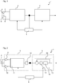
- FIG. 1 schematically shows a block diagram of a MEMS microphone 1.
- the MEMS microphone 1 comprises a transducer element 2, a first part 3, a second part 4 and a gain control unit 5.
- the transducer element 2 is adapted to convert acoustical signals into electrical signals.
- the MEMS microphone 1 shown in Figure 1 comprises a differential transducer element comprising a displaceable diaphragm 6, a first backplate 7 and a second backplate 8.
- the displaceable diaphragm 6 is arranged between the two backplates 7, 8 and a bias voltage is applied to the diaphragm 6. Accordingly, this transducer element 2 provides two electrical signals. Each of the electrical signals corresponds to the capacity between the displaceable diaphragm 6 and the first or, respectively, the second backplate 7, 8.
- first part 3, the second part 4 and the gain control unit 5 form a signal processing circuit of the MEMS microphone 1.
- the signal processing circuit is adapted to process the signal provided by the transducer element 2 and to provide an output signal of the MEMS microphone 1, preferably to provide a single-bit digital signal as an output signal.
- the signal processing circuit is composed only of the first part 3, the second part 4 and the gain control unit 5.
- the signal processing circuit may further comprise other parts or components.
- the invention is not limited to MEMS microphones 1 comprising differential transducer elements.
- the MEMS microphone 1 may comprise a transducer element 3 having only one displaceable diaphragm 6 and one backplate 7 and, therefore, providing only one electrical signal to the first part 3.
- each part 3, 4 may be circuits. Accordingly, each part 3, 4 may comprise electrical components. In particular, each part 3, 4 may comprise linear elements and/or other components, e.g. a Sigma-Delta Modulator. Further, each part 3, 4 may comprise a main path connecting an input port and an output port wherein at least some of the components are arranged along the main path. Accordingly, an input signal may be fed to the input port of the main path. Further, the signal may be processed by the components. The processed signal may be provided at the output port of the part 3, 4. The processing of the signal carried out by the components of the part 3, 4 comprises at least one of an amplification of the signal, a filtering of the signal and a conversion from an analogue signal to a digital signal or vice versa.
- a part 3, 4 may also be a circuit being free from components.
- a part 3, 4 may be a sub-part of a circuit.
- the first part 3 is adapted to process the electrical signals provided by the transducer element 2.
- the processing of the electrical signals may correspond to a conversion from analog signals into digital signals.
- the processing of the signals corresponds to an amplification of the amplitude of the signal.
- a parameter A1 describes a gain setting of the first part 3.
- the gain setting A1 corresponds to the amplification factor by which the first part 3 amplifies the signal received from the transducer element 2.
- the gain setting A1 may also correspond to setting a linearity range of the first part 3.
- the processed signal provided by the first part 3 is fed to the second part 4 as an input signal.
- the second part 4 processes the processed signal again and provides an output signal of the MEMS microphone 1.
- This output signal is preferably a digital signal.
- the output signal is a digital single-bit signal.
- the second part 4 may process the signal provided by the first part 3 by converting it into a digital single-bit signal. Further, the second part 4 processes the signal provided by the first part 3 by amplifying the signal.
- the second part 4 has an adjustable gain setting.
- This gain setting corresponds to the amplification factor by which the amplitude of the processed signal is amplified.
- the gain setting may also correspond to a setting of a full scale range of the second part.
- the gain setting of the second part 4 is set to a factor given by parameter A2.
- the product of the parameters A1 and A2 is constant.
- the gain setting A2 of the second part 4 is reciprocally proportional to the gain setting A1 of the first part 3. Accordingly, any adjustments of the gain setting A1 of the first part 3 are compensated in the second part 4, thereby providing a linear input-output relationship of the MEMS microphone 1.
- the output signal of the MEMS microphone 1 is proportional to the input signal measured by the transducer element 2 as the gain setting of the first part 3 given by parameter A1 and the gain setting of the second part 4 given by parameter A2 are amended such that the product of the parameters A1 and A2 remains constant. Accordingly, it is chosen from a wide variety of gain settings for the first part 3 as the adjustable gain setting of the second part 4 allows compensating for any changes in the gain setting of the first part 3.
- the MEMS microphone 1 further comprises the gain control unit 5 which is enabled to adjust the gain settings of the first and the second part 3, 4.
- the processed signal which is provided by the first part 3 is also fed into the gain control unit 5 as an input parameter. Based on the amplitude of this signal, the gain control unit 5 is enabled to change the gain settings of the first and the second part 3, 4. Accordingly, the gain control unit 5 is connected to the first part 3 and to the second part 4. Further, the gain control unit 5 is enabled to send control signals to each of the first and the second part 3, 4.
- the gain control unit 5 monitors the amplitude of the processed signal provided by the first part 3. If this amplitude exceeds a first threshold value, the gain control unit 5 decreases the gain setting of the first part 3 and increases the gain setting of the second part 4.
- the first threshold value may correspond to a certain percentage of the linearity range of the first part 3.
- the gain control unit 5 deduces that the electrical signal provided by the transducer element 2 to the first part 3 is exceeding a value corresponding to e.g. 70% of the linearity range of the first part 3. Accordingly, the gain control unit 5 decreases the gain setting of the first part 3 which, in this case, corresponds to increasing the linearity range.
- the MEMS microphone 1 can operate up to a high maximum sound pressure level.
- the MEMS microphone 1 can be operated up to a sound pressure level of 140 dB without an overflow of any of the parts.
- the gain control unit 5 increases the gain setting of the first part 3 and decreases the gain setting of the second part 4.
- the gain control unit 5 comprises a timer which is not shown in the Figures.
- the given period of time may be in the range of milliseconds, e.g. in the range from 1 to 100 milliseconds.
- the linearity range of the first part 3 and the gain setting of the first part is adapted such that a sufficient Signal-to-Noise ratio is guaranteed.
- the first part 3 may comprise elements for analog processing of the signal provided by the transducer element 2.
- the second part 4 comprises elements for digitally processing a signal.
- any gain adjustment in the first part 3 is reciprocally applied to the second part 4
- any gain adjustments made by the analog elements is being compensated digitally in the second part 4.
- the output signal provided by the MEMS microphone 1 is independent of the gain settings of the first and the second part 3, 4.
- a linear relationship between the amplitude of the electrical signal provided by the transducer element 2 and the output signal provided by the second part 4 is ensured.
- FIG. 2 shows a more detailed block diagram of the MEMS microphone 1 according to a first embodiment.
- the first part 3 comprises a first and a second preamplifier 9, 10, an Analogue-to-Digital Sigma-Delta Modulator 11 and an averaging filter 12.
- the averaging filter 12 is a component which converts a single-bit digital signal having a first signal rate into a multi-bit digital signal at the same rate as the input signal. For every single-bit input sample, it calculates and outputs the average of the current and previous n-1 input samples. Thus it provides an output signal having n+1 levels.
- the first part 3 processes the signal provided by the transducer element 2. Thereby, the first part 3 amplifies the signal by an amplification factor given by the overall gain setting A1 of the first part.
- the differential transducer element 2 provides two electrical signals. Each of said signals is fed to one preamplifier 9, 10.
- the first and the second preamplifier 9, 10 are arranged in parallel paths.
- the first and the second preamplifier 9, 10 each amplify the amplitude of the respective electrical signal and provide an analog output signal to the Analogue-to-Digital Sigma-Delta Modulator 11.
- the first and the second preamplifier 9, 10 preferably are set to the same gain setting such that the signal strength in both paths is identical. Alternatively, the first and the second preamplifier 9, 10 may also be set to different gain settings.
- the transducer element 2 may provide only one electrical signal.
- the first part 3 may comprise only one preamplifier 9.
- the preamplifier 9 increases the amplitude of the signal by a factor A1 PREAMP .
- the gain setting of the preamplifiers 9, 10, i.e. the parameter A1 PREAMP is adjustable.
- the gain control unit 5 is adapted to adjust the gain setting of the first and of the second preamplifier 9, 10.
- the Analogue-to-Digital Sigma-Delta Modulator 11 is enabled to transform the analog signals provided by the transducer element 2 into digital signals.
- the Analogue-to-Digital Sigma-Delta Modulator 11 has an adjustable full scale range.
- the parameter A1 SDM describes the setting of the adjustable full scale range.
- the Analogue-to-Digital Sigma-Delta Modulator 11 provides a single-bit digital output signal. This signal is fed to the averaging filter 12 which is connected in line with the Analogue-to-Digital Sigma-Delta Modulator 11.
- the overall gain setting A1 of the first part is proportional to the parameter A1 PREAMP describing the gain of the preamplifiers 9, 10 and proportional to the parameter A1 SDM describing the setting of the adjustable full scale range of the Analogue-to-Digital Sigma-Delta Modulator 11.
- the averaging filter 12 generates a digital multi-bit signal. Accordingly, the averaging filter 12 samples the signals provided by the Analogue-to-Digital Sigma-Delta Modulator 11 over a given number of n bits and provides an output signal having n+1 levels. This digital multi-bit signal is fed to the second part 4 and to the gain control unit 5.
- the gain control unit 5 monitors the output signal provided by the averaging filter 12. Based on this signal, the gain control unit 5 is enabled to set the overall gain setting A1 of the first part 3 by setting the parameter A1 PREAMP corresponding to the gain setting of the preamplifiers 9, 10 and the parameter A1 SDM corresponding to the full scale range setting of the Analogue-to-Digital Sigma-Delta Modulator 11.
- the gain setting A1 of the first part 3 is decreased and the linearity range of the first part 3 is extended, if the signal provided by the averaging filter 12 exceeds a first threshold value. Further, if the signal provided by the averaging filter 12 remains below a second threshold value for a given period of time, the gain setting A1 of the first part 3 is increased and the linearity range of the first part 3 is reduced.
- the gain setting and the full scale range of the second part is in both cases adjusted reciprocally.
- the second part 4 comprises a digital Sigma-Delta Modulator 13.
- the digital Sigma-Delta Modulator 13 comprises a digital loop filter 14 and a quantizer 15. Further, the digital Sigma-Delta Modulator 13 comprises a feedback path 16.
- a parameter A FORWARD describes the forward gain and a parameter A FEEDBACK describes the feedback gain of the feedback path 16.
- the parameters A FORWARD and A FEEDBACK are adjustable. In particular, they may be adjusted by the gain control unit 5.
- the setting of the overall gain A2 of the second part 4 is amended by setting the parameters A FORWARD and A FEEDBACK .
- the overall gain A2 of the second part 4 is amended whenever the setting of the parameters A1 PREAMP and A1 SDM of the first part 3 is altered. Accordingly, a change in the gain setting A1 of the first part 3 is compensated by a corresponding change in the gain setting A2 of the second part 4.
- Analogue-to-Digital Sigma-Delta Modulator 11 of the first part 3 is not shown in Figure 2 .
- the Analogue-to-Digital Sigma-Delta Modulator 11 may have a structure similar to the structure of the digital Sigma-Delta Modulator 13 shown in Figure 2 .
- Figure 3 shows a second embodiment of the MEMS microphone 1.
- the second embodiment differs from the first embodiment in that the Analogue-to-Digital Sigma-Delta Modulator 11 provides a multi-bit output signal. Therefore, the averaging filter 12 is not needed anymore to convert a single-bit signal into a multi-bit signal.
- the second embodiment is identical to the first embodiment.
- the Analogue-to-Digital Sigma-Delta Modulator 11 of the first part 3 can be of the type switched capacitor or continuous type. Further, it can provide a single-bit signal as shown in Figure 2 or a multi-bit signal as shown in Figure 3 . Further, the digital Sigma-Delta Modulator 13 of the second part 4 provides a single-bit output signal.
- the loop filter 14 must be implemented with a sufficiently large number of bits to achieve a dynamic range that is bigger than the required system dynamic range which may be up to 112 dB.
Landscapes
- Engineering & Computer Science (AREA)
- Physics & Mathematics (AREA)
- Acoustics & Sound (AREA)
- Signal Processing (AREA)
- Multimedia (AREA)
- Circuit For Audible Band Transducer (AREA)
- Electrostatic, Electromagnetic, Magneto- Strictive, And Variable-Resistance Transducers (AREA)
- Control Of Amplification And Gain Control (AREA)
Claims (10)
- MEMS-Mikrofon (1), das Folgendes umfasst:ein Wandlerelement (2) zum Bereitstellen eines elektrischen Signals,einen ersten Teil (3) zum Empfangen des elektrischen Signals von dem Wandlerelement (2) und zum Bereitstellen eines verarbeiteten Signals,einen zweiten Teil (4) zum Empfangen des verarbeiteten Signals von dem ersten Teil (3) und zum Bereitstellen eines Ausgangssignals des MEMS-Mikrofons (1), undeine Verstärkungssteuereinheit (5), die in der Lage ist, eine Verstärkungseinstellung des ersten Teils (3) und eine Verstärkungseinstellung des zweiten Teils (4) einzustellen,wobei die Verstärkungssteuereinheit (5) dazu ausgebildet ist, die Amplitude des verarbeiteten Signals, das von dem ersten Teil (3) bereitgestellt wird, zu überwachen und die Verstärkungseinstellungen des ersten Teils (3) und des zweiten Teils (4) basierend auf der Amplitude des verarbeiteten Signals, das von dem ersten Teil (3) bereitgestellt wird, einzustellen, um einen Überlauf oder ein Clipping des ersten Teils zu vermeiden, und wobei,- falls die Amplitude einen ersten Schwellenwert überschreitet, die Steuereinheit (5) die Verstärkungseinstellung des ersten Teils (3) verringert und die Verstärkungseinstellung des zweiten Teils (4) erhöht, und- falls die Amplitude während einer bestimmten Zeitspanne unter einem zweiten Schwellenwert verbleibt, die Steuereinheit dazu ausgebildet ist, die Verstärkungseinstellungen des ersten Teils zu erhöhen und die Verstärkungseinstellung des zweiten Teils zu verringern, undwobei die Verstärkungssteuereinheit (5) in der Lage ist, die Verstärkungseinstellung des ersten Teils (3) einzustellen, indem ein Verstärkungsfaktor A1 des ersten Teils (3) geändert wird,wobei die Verstärkungssteuereinheit (5) in der Lage ist, die Verstärkungseinstellung des zweiten Teils (4) einzustellen, indem ein Verstärkungsfaktor A2 des zweiten Teils (4) geändert wird,wobei die Verstärkungssteuereinheit (5) in der Lage ist, die Verstärkungseinstellungen des ersten Teils (3) und des zweiten Teils (4) so einzustellen, dass ein Produkt der Verstärkungsfaktoren A1 und A2 konstant bleibt.
- MEMS-Mikrofon (1) gemäß dem vorhergehenden Anspruch,
wobei der erste Teil (3) einen Analog-Digital-Sigma-Delta-Modulator (11) umfasst, der eine einstellbare Verstärkungseinstellung aufweist. - MEMS-Mikrofon (1) gemäß dem vorhergehenden Anspruch,
wobei die Einstellung der Verstärkungseinstellung des Analog-Digital-Sigma-Delta-Modulators (11) eine Änderung des vollen Skalenbereichs des Analog-Digital-Sigma-Delta-Modulators (11) umfasst. - MEMS-Mikrofon (1) gemäß einem beliebigen der vorhergehenden Ansprüche,
wobei der erste Teil (3) einen Vorverstärker (9, 10) mit einer einstellbaren Verstärkungseinstellung umfasst. - MEMS-Mikrofon (1) gemäß einem beliebigen der vorhergehenden Ansprüche,
wobei der zweite Teil (4) einen digitalen Sigma-Delta-Modulator (13) umfasst, der eine einstellbare Verstärkungseinstellung aufweist. - MEMS-Mikrofon (1) gemäß dem vorhergehenden Anspruch,
wobei die Einstellung der Verstärkungseinstellung des digitalen Sigma-Delta-Modulators (13) eine Änderung des vollen Skalenbereichs des digitalen Sigma-Delta-Modulators (13) umfasst. - MEMS-Mikrofon (1) gemäß einem beliebigen der vorhergehenden Ansprüche,
wobei das Wandlerelement (2) ein Differentialwandlerelement zum Bereitstellen von zwei elektrischen Signalen an den ersten Teil (3) ist. - MEMS-Mikrofon (1) gemäß einem beliebigen der vorhergehenden Ansprüche,
wobei das von dem Wandlerelement (2) bereitgestellte elektrische Signal ein analoges Signal ist, und wobei der erste Teil (3) dieses Signal so umwandelt, dass das verarbeitete Signal ein digitales Signal ist. - MEMS-Mikrofon (1) gemäß dem vorhergehenden Anspruch,
wobei das vom ersten Teil (3) bereitgestellte verarbeitete Signal ein digitales Multi-Bit-Signal ist und der zweite Teil (4) dieses Signal in ein digitales Single-Bit-Signal umwandelt. - Verfahren zum Betreiben eines MEMS-Mikrofons (1), wobei das MEMS-Mikrofon (1) Folgendes umfasst:ein Wandlerelement (2) zum Bereitstellen eines elektrischen Signals,einen ersten Teil (3) zum Empfangen des elektrischen Signals von dem Wandlerelement (2) und zum Bereitstellen eines verarbeiteten Signals,einen zweiten Teil (4) zum Empfangen des verarbeiteten Signals von dem ersten Teil (3) und zum Bereitstellen eines Ausgangssignals des MEMS-Mikrofons (1), undeine Verstärkungssteuereinheit (5),wobei das Verfahren das Einstellen einer Verstärkungseinstellung des ersten Teils (3) und das Einstellen einer Verstärkungseinstellung des zweiten Teils (4) umfasst, undwobei die Verstärkungssteuereinheit (5) die Amplitude des verarbeiteten Signals, das von dem ersten Teil (3) bereitgestellt wird, überwacht und die Verstärkungseinstellungen des ersten Teils (3) und des zweiten Teils (4) basierend auf der Amplitude des verarbeiteten Signals, das von dem ersten Teil (3) bereitgestellt wird, einstellt, um einen Überlauf oder ein Clipping des ersten Teils zu vermeiden,wobei,- falls die Amplitude einen ersten Schwellenwert überschreitet, die Steuereinheit (5) die Verstärkungseinstellung des ersten Teils (3) verringert und die Verstärkungseinstellung des zweiten Teils (4) erhöht, und- falls die Amplitude während einer bestimmten Zeitspanne unter einem zweiten Schwellenwert verbleibt, die Steuereinheit die Verstärkungseinstellungen des ersten Teils erhöht und die Verstärkungseinstellung des zweiten Teils verringert, undwobei die Einstellung der Verstärkungseinstellung des ersten Teils (3) durch Ändern eines Verstärkungsfaktors A1 des ersten Teils (3) durchgeführt wird,wobei die Einstellung der Verstärkungseinstellung des zweiten Teils (4) durch Ändern eines Verstärkungsfaktors A2 des zweiten Teils (4) durchgeführt wird,wobei die Verstärkungseinstellungen des ersten Teils (3) und des zweiten Teils (4) so eingestellt werden, dass ein Produkt der Verstärkungsfaktoren A1 und A2 konstant bleibt.
Applications Claiming Priority (1)
| Application Number | Priority Date | Filing Date | Title |
|---|---|---|---|
| PCT/EP2012/065764 WO2014023363A1 (en) | 2012-08-10 | 2012-08-10 | Mems microphone and method of operating the mems microphone |
Publications (2)
| Publication Number | Publication Date |
|---|---|
| EP2883364A1 EP2883364A1 (de) | 2015-06-17 |
| EP2883364B1 true EP2883364B1 (de) | 2021-12-22 |
Family
ID=46724389
Family Applications (1)
| Application Number | Title | Priority Date | Filing Date |
|---|---|---|---|
| EP12750576.6A Active EP2883364B1 (de) | 2012-08-10 | 2012-08-10 | Mems-mikrofon und verfahren zum betrieb des mems-mikrofons |
Country Status (4)
| Country | Link |
|---|---|
| US (1) | US9673767B2 (de) |
| EP (1) | EP2883364B1 (de) |
| JP (1) | JP6085678B2 (de) |
| WO (1) | WO2014023363A1 (de) |
Families Citing this family (8)
| Publication number | Priority date | Publication date | Assignee | Title |
|---|---|---|---|---|
| US9414175B2 (en) * | 2013-07-03 | 2016-08-09 | Robert Bosch Gmbh | Microphone test procedure |
| WO2015176745A1 (en) | 2014-05-20 | 2015-11-26 | Epcos Ag | Microphone and method of operating a microphone |
| US10325584B2 (en) * | 2014-12-10 | 2019-06-18 | Stmicroelectronics S.R.L. | Active noise cancelling device and method of actively cancelling acoustic noise |
| JP6694168B2 (ja) * | 2015-07-27 | 2020-05-13 | Tdk株式会社 | マイクロフォン用の電子回路及びそのマイクロフォン |
| FR3056813B1 (fr) * | 2016-09-29 | 2019-11-08 | Dolphin Integration | Circuit audio et procede de detection d'activite |
| US10237650B2 (en) * | 2017-06-05 | 2019-03-19 | Invensense, Inc. | Sensor component with enhanced acoustic overload point and electrostatic discharge protection |
| WO2025004278A1 (ja) * | 2023-06-29 | 2025-01-02 | 日清紡マイクロデバイス株式会社 | マイクロホン信号変換モジュール及びマイクロホンモジュール |
| US12627927B2 (en) * | 2024-03-26 | 2026-05-12 | Qualcomm Incorporated | Fast response audio signal processing system |
Family Cites Families (5)
| Publication number | Priority date | Publication date | Assignee | Title |
|---|---|---|---|---|
| DE2929688A1 (de) | 1979-07-21 | 1981-02-12 | Bosch Gmbh Robert | Elektronisches stethoskop |
| CN1879446B (zh) * | 2003-11-24 | 2011-02-16 | 桑尼奥公司 | 包括整体多电平量化器和单比特转换装置的麦克风 |
| US8223981B2 (en) | 2008-05-23 | 2012-07-17 | Analog Devices, Inc. | Wide dynamic range microphone |
| US8160527B2 (en) * | 2009-03-30 | 2012-04-17 | Telefonaktiebolaget Lm Ericsson (Publ) | Automatic gain control in multi-carrier wireless systems |
| EP2485395B1 (de) | 2011-02-04 | 2013-05-01 | Harman International Industries Ltd. | Audiomischkonsole, die eine Signalpegelüberlastung vermeidet |
-
2012
- 2012-04-10 US US14/420,324 patent/US9673767B2/en active Active
- 2012-08-10 EP EP12750576.6A patent/EP2883364B1/de active Active
- 2012-08-10 WO PCT/EP2012/065764 patent/WO2014023363A1/en not_active Ceased
- 2012-08-10 JP JP2015525752A patent/JP6085678B2/ja not_active Expired - Fee Related
Also Published As
| Publication number | Publication date |
|---|---|
| US9673767B2 (en) | 2017-06-06 |
| WO2014023363A1 (en) | 2014-02-13 |
| JP6085678B2 (ja) | 2017-02-22 |
| JP2015530024A (ja) | 2015-10-08 |
| EP2883364A1 (de) | 2015-06-17 |
| US20150318833A1 (en) | 2015-11-05 |
Similar Documents
| Publication | Publication Date | Title |
|---|---|---|
| US9673767B2 (en) | MEMS microphone and method of operating the MEMS microphone | |
| US9673768B2 (en) | Multipath digital microphones | |
| US9071214B2 (en) | Audio signal controller | |
| US9083288B2 (en) | High level capable audio amplification circuit | |
| US11637537B2 (en) | Method for improving die area and power efficiency in high dynamic range digital microphones | |
| US9525940B1 (en) | Multi-path analog front end and analog-to-digital converter for a signal processing system | |
| US20130129117A1 (en) | Audio amplification circuit | |
| EP2312747B1 (de) | Verzerrungskompensation | |
| EP1753130B1 (de) | Analog/Digital - Wandler mit dynamischer Bereichserweiterung | |
| US9716933B2 (en) | Method and apparatus for improving performance of digital microelectromechanical systems microphones | |
| EP2653845B1 (de) | Sensorschaltung und Kalibrierverfahren | |
| US9780800B1 (en) | Matching paths in a multiple path analog-to-digital converter | |
| CN101044685B (zh) | 信号接收机和移动通信设备 | |
| CN109690953B (zh) | 具有自适应路径的多路径模拟前端 | |
| GB2553867A (en) | Reconfiguring paths in a multiple path analog-to-digital converter | |
| KR20190039552A (ko) | 입력 신호 충실도 및 출력 요건들에 기초한 다중 경로 지상 분열 | |
| US10181845B1 (en) | Calibration of a dual-path pulse width modulation system | |
| TWI571063B (zh) | 自動校正動態範圍之低功耗三角積分調變器架構及其低功耗電路實現方法與自動校正且延伸三角積分調變器動態範圍之方法 | |
| CN1700603B (zh) | 模拟信号数字化的装置和方法 | |
| US8823565B2 (en) | Semiconductor device having analog-to-digital converter with gain-dependent dithering and communication apparatus | |
| CN105846840A (zh) | 接收机电路以及用于控制接收机电路增益的方法 | |
| US10763889B1 (en) | Analog-to-digital converter with dynamic range enhancer | |
| US9071216B2 (en) | Signal processing device and signal processing method | |
| KR20160054166A (ko) | 디지털 오디오 앰프 | |
| AU2005296358B2 (en) | An amplifier apparatus and method |
Legal Events
| Date | Code | Title | Description |
|---|---|---|---|
| PUAI | Public reference made under article 153(3) epc to a published international application that has entered the european phase |
Free format text: ORIGINAL CODE: 0009012 |
|
| 17P | Request for examination filed |
Effective date: 20141212 |
|
| AK | Designated contracting states |
Kind code of ref document: A1 Designated state(s): AL AT BE BG CH CY CZ DE DK EE ES FI FR GB GR HR HU IE IS IT LI LT LU LV MC MK MT NL NO PL PT RO RS SE SI SK SM TR |
|
| AX | Request for extension of the european patent |
Extension state: BA ME |
|
| DAX | Request for extension of the european patent (deleted) | ||
| RAP1 | Party data changed (applicant data changed or rights of an application transferred) |
Owner name: TDK CORPORATION |
|
| STAA | Information on the status of an ep patent application or granted ep patent |
Free format text: STATUS: REQUEST FOR EXAMINATION WAS MADE |
|
| R17P | Request for examination filed (corrected) |
Effective date: 20141212 |
|
| STAA | Information on the status of an ep patent application or granted ep patent |
Free format text: STATUS: EXAMINATION IS IN PROGRESS |
|
| 17Q | First examination report despatched |
Effective date: 20190523 |
|
| GRAP | Despatch of communication of intention to grant a patent |
Free format text: ORIGINAL CODE: EPIDOSNIGR1 |
|
| STAA | Information on the status of an ep patent application or granted ep patent |
Free format text: STATUS: GRANT OF PATENT IS INTENDED |
|
| INTG | Intention to grant announced |
Effective date: 20210707 |
|
| GRAS | Grant fee paid |
Free format text: ORIGINAL CODE: EPIDOSNIGR3 |
|
| GRAA | (expected) grant |
Free format text: ORIGINAL CODE: 0009210 |
|
| STAA | Information on the status of an ep patent application or granted ep patent |
Free format text: STATUS: THE PATENT HAS BEEN GRANTED |
|
| AK | Designated contracting states |
Kind code of ref document: B1 Designated state(s): AL AT BE BG CH CY CZ DE DK EE ES FI FR GB GR HR HU IE IS IT LI LT LU LV MC MK MT NL NO PL PT RO RS SE SI SK SM TR |
|
| REG | Reference to a national code |
Ref country code: GB Ref legal event code: FG4D |
|
| REG | Reference to a national code |
Ref country code: CH Ref legal event code: EP |
|
| REG | Reference to a national code |
Ref country code: DE Ref legal event code: R096 Ref document number: 602012077409 Country of ref document: DE |
|
| REG | Reference to a national code |
Ref country code: AT Ref legal event code: REF Ref document number: 1457885 Country of ref document: AT Kind code of ref document: T Effective date: 20220115 |
|
| REG | Reference to a national code |
Ref country code: IE Ref legal event code: FG4D |
|
| REG | Reference to a national code |
Ref country code: LT Ref legal event code: MG9D |
|
| PG25 | Lapsed in a contracting state [announced via postgrant information from national office to epo] |
Ref country code: RS Free format text: LAPSE BECAUSE OF FAILURE TO SUBMIT A TRANSLATION OF THE DESCRIPTION OR TO PAY THE FEE WITHIN THE PRESCRIBED TIME-LIMIT Effective date: 20211222 Ref country code: LT Free format text: LAPSE BECAUSE OF FAILURE TO SUBMIT A TRANSLATION OF THE DESCRIPTION OR TO PAY THE FEE WITHIN THE PRESCRIBED TIME-LIMIT Effective date: 20211222 Ref country code: FI Free format text: LAPSE BECAUSE OF FAILURE TO SUBMIT A TRANSLATION OF THE DESCRIPTION OR TO PAY THE FEE WITHIN THE PRESCRIBED TIME-LIMIT Effective date: 20211222 Ref country code: BG Free format text: LAPSE BECAUSE OF FAILURE TO SUBMIT A TRANSLATION OF THE DESCRIPTION OR TO PAY THE FEE WITHIN THE PRESCRIBED TIME-LIMIT Effective date: 20220322 |
|
| REG | Reference to a national code |
Ref country code: NL Ref legal event code: MP Effective date: 20211222 |
|
| REG | Reference to a national code |
Ref country code: AT Ref legal event code: MK05 Ref document number: 1457885 Country of ref document: AT Kind code of ref document: T Effective date: 20211222 |
|
| PG25 | Lapsed in a contracting state [announced via postgrant information from national office to epo] |
Ref country code: SE Free format text: LAPSE BECAUSE OF FAILURE TO SUBMIT A TRANSLATION OF THE DESCRIPTION OR TO PAY THE FEE WITHIN THE PRESCRIBED TIME-LIMIT Effective date: 20211222 Ref country code: NO Free format text: LAPSE BECAUSE OF FAILURE TO SUBMIT A TRANSLATION OF THE DESCRIPTION OR TO PAY THE FEE WITHIN THE PRESCRIBED TIME-LIMIT Effective date: 20220322 Ref country code: LV Free format text: LAPSE BECAUSE OF FAILURE TO SUBMIT A TRANSLATION OF THE DESCRIPTION OR TO PAY THE FEE WITHIN THE PRESCRIBED TIME-LIMIT Effective date: 20211222 Ref country code: HR Free format text: LAPSE BECAUSE OF FAILURE TO SUBMIT A TRANSLATION OF THE DESCRIPTION OR TO PAY THE FEE WITHIN THE PRESCRIBED TIME-LIMIT Effective date: 20211222 Ref country code: GR Free format text: LAPSE BECAUSE OF FAILURE TO SUBMIT A TRANSLATION OF THE DESCRIPTION OR TO PAY THE FEE WITHIN THE PRESCRIBED TIME-LIMIT Effective date: 20220323 |
|
| PG25 | Lapsed in a contracting state [announced via postgrant information from national office to epo] |
Ref country code: NL Free format text: LAPSE BECAUSE OF FAILURE TO SUBMIT A TRANSLATION OF THE DESCRIPTION OR TO PAY THE FEE WITHIN THE PRESCRIBED TIME-LIMIT Effective date: 20211222 |
|
| PG25 | Lapsed in a contracting state [announced via postgrant information from national office to epo] |
Ref country code: SM Free format text: LAPSE BECAUSE OF FAILURE TO SUBMIT A TRANSLATION OF THE DESCRIPTION OR TO PAY THE FEE WITHIN THE PRESCRIBED TIME-LIMIT Effective date: 20211222 Ref country code: SK Free format text: LAPSE BECAUSE OF FAILURE TO SUBMIT A TRANSLATION OF THE DESCRIPTION OR TO PAY THE FEE WITHIN THE PRESCRIBED TIME-LIMIT Effective date: 20211222 Ref country code: RO Free format text: LAPSE BECAUSE OF FAILURE TO SUBMIT A TRANSLATION OF THE DESCRIPTION OR TO PAY THE FEE WITHIN THE PRESCRIBED TIME-LIMIT Effective date: 20211222 Ref country code: PT Free format text: LAPSE BECAUSE OF FAILURE TO SUBMIT A TRANSLATION OF THE DESCRIPTION OR TO PAY THE FEE WITHIN THE PRESCRIBED TIME-LIMIT Effective date: 20220422 Ref country code: ES Free format text: LAPSE BECAUSE OF FAILURE TO SUBMIT A TRANSLATION OF THE DESCRIPTION OR TO PAY THE FEE WITHIN THE PRESCRIBED TIME-LIMIT Effective date: 20211222 Ref country code: EE Free format text: LAPSE BECAUSE OF FAILURE TO SUBMIT A TRANSLATION OF THE DESCRIPTION OR TO PAY THE FEE WITHIN THE PRESCRIBED TIME-LIMIT Effective date: 20211222 Ref country code: CZ Free format text: LAPSE BECAUSE OF FAILURE TO SUBMIT A TRANSLATION OF THE DESCRIPTION OR TO PAY THE FEE WITHIN THE PRESCRIBED TIME-LIMIT Effective date: 20211222 |
|
| PG25 | Lapsed in a contracting state [announced via postgrant information from national office to epo] |
Ref country code: PL Free format text: LAPSE BECAUSE OF FAILURE TO SUBMIT A TRANSLATION OF THE DESCRIPTION OR TO PAY THE FEE WITHIN THE PRESCRIBED TIME-LIMIT Effective date: 20211222 Ref country code: AT Free format text: LAPSE BECAUSE OF FAILURE TO SUBMIT A TRANSLATION OF THE DESCRIPTION OR TO PAY THE FEE WITHIN THE PRESCRIBED TIME-LIMIT Effective date: 20211222 |
|
| REG | Reference to a national code |
Ref country code: DE Ref legal event code: R097 Ref document number: 602012077409 Country of ref document: DE |
|
| PG25 | Lapsed in a contracting state [announced via postgrant information from national office to epo] |
Ref country code: IS Free format text: LAPSE BECAUSE OF FAILURE TO SUBMIT A TRANSLATION OF THE DESCRIPTION OR TO PAY THE FEE WITHIN THE PRESCRIBED TIME-LIMIT Effective date: 20220422 |
|
| PLBE | No opposition filed within time limit |
Free format text: ORIGINAL CODE: 0009261 |
|
| STAA | Information on the status of an ep patent application or granted ep patent |
Free format text: STATUS: NO OPPOSITION FILED WITHIN TIME LIMIT |
|
| PG25 | Lapsed in a contracting state [announced via postgrant information from national office to epo] |
Ref country code: DK Free format text: LAPSE BECAUSE OF FAILURE TO SUBMIT A TRANSLATION OF THE DESCRIPTION OR TO PAY THE FEE WITHIN THE PRESCRIBED TIME-LIMIT Effective date: 20211222 Ref country code: AL Free format text: LAPSE BECAUSE OF FAILURE TO SUBMIT A TRANSLATION OF THE DESCRIPTION OR TO PAY THE FEE WITHIN THE PRESCRIBED TIME-LIMIT Effective date: 20211222 |
|
| 26N | No opposition filed |
Effective date: 20220923 |
|
| PG25 | Lapsed in a contracting state [announced via postgrant information from national office to epo] |
Ref country code: SI Free format text: LAPSE BECAUSE OF FAILURE TO SUBMIT A TRANSLATION OF THE DESCRIPTION OR TO PAY THE FEE WITHIN THE PRESCRIBED TIME-LIMIT Effective date: 20211222 |
|
| PG25 | Lapsed in a contracting state [announced via postgrant information from national office to epo] |
Ref country code: MC Free format text: LAPSE BECAUSE OF FAILURE TO SUBMIT A TRANSLATION OF THE DESCRIPTION OR TO PAY THE FEE WITHIN THE PRESCRIBED TIME-LIMIT Effective date: 20211222 |
|
| REG | Reference to a national code |
Ref country code: CH Ref legal event code: PL |
|
| GBPC | Gb: european patent ceased through non-payment of renewal fee |
Effective date: 20220810 |
|
| PG25 | Lapsed in a contracting state [announced via postgrant information from national office to epo] |
Ref country code: LU Free format text: LAPSE BECAUSE OF NON-PAYMENT OF DUE FEES Effective date: 20220810 Ref country code: LI Free format text: LAPSE BECAUSE OF NON-PAYMENT OF DUE FEES Effective date: 20220831 Ref country code: CH Free format text: LAPSE BECAUSE OF NON-PAYMENT OF DUE FEES Effective date: 20220831 |
|
| REG | Reference to a national code |
Ref country code: BE Ref legal event code: MM Effective date: 20220831 |
|
| PG25 | Lapsed in a contracting state [announced via postgrant information from national office to epo] |
Ref country code: IT Free format text: LAPSE BECAUSE OF FAILURE TO SUBMIT A TRANSLATION OF THE DESCRIPTION OR TO PAY THE FEE WITHIN THE PRESCRIBED TIME-LIMIT Effective date: 20211222 |
|
| PG25 | Lapsed in a contracting state [announced via postgrant information from national office to epo] |
Ref country code: IE Free format text: LAPSE BECAUSE OF NON-PAYMENT OF DUE FEES Effective date: 20220810 Ref country code: FR Free format text: LAPSE BECAUSE OF NON-PAYMENT OF DUE FEES Effective date: 20220831 |
|
| P01 | Opt-out of the competence of the unified patent court (upc) registered |
Effective date: 20230706 |
|
| PG25 | Lapsed in a contracting state [announced via postgrant information from national office to epo] |
Ref country code: BE Free format text: LAPSE BECAUSE OF NON-PAYMENT OF DUE FEES Effective date: 20220831 |
|
| PG25 | Lapsed in a contracting state [announced via postgrant information from national office to epo] |
Ref country code: GB Free format text: LAPSE BECAUSE OF NON-PAYMENT OF DUE FEES Effective date: 20220810 |
|
| PG25 | Lapsed in a contracting state [announced via postgrant information from national office to epo] |
Ref country code: HU Free format text: LAPSE BECAUSE OF FAILURE TO SUBMIT A TRANSLATION OF THE DESCRIPTION OR TO PAY THE FEE WITHIN THE PRESCRIBED TIME-LIMIT; INVALID AB INITIO Effective date: 20120810 |
|
| PG25 | Lapsed in a contracting state [announced via postgrant information from national office to epo] |
Ref country code: CY Free format text: LAPSE BECAUSE OF FAILURE TO SUBMIT A TRANSLATION OF THE DESCRIPTION OR TO PAY THE FEE WITHIN THE PRESCRIBED TIME-LIMIT Effective date: 20211222 |
|
| PG25 | Lapsed in a contracting state [announced via postgrant information from national office to epo] |
Ref country code: MK Free format text: LAPSE BECAUSE OF FAILURE TO SUBMIT A TRANSLATION OF THE DESCRIPTION OR TO PAY THE FEE WITHIN THE PRESCRIBED TIME-LIMIT Effective date: 20211222 |
|
| PG25 | Lapsed in a contracting state [announced via postgrant information from national office to epo] |
Ref country code: TR Free format text: LAPSE BECAUSE OF FAILURE TO SUBMIT A TRANSLATION OF THE DESCRIPTION OR TO PAY THE FEE WITHIN THE PRESCRIBED TIME-LIMIT Effective date: 20211222 |
|
| PG25 | Lapsed in a contracting state [announced via postgrant information from national office to epo] |
Ref country code: MT Free format text: LAPSE BECAUSE OF FAILURE TO SUBMIT A TRANSLATION OF THE DESCRIPTION OR TO PAY THE FEE WITHIN THE PRESCRIBED TIME-LIMIT Effective date: 20211222 |
|
| PGFP | Annual fee paid to national office [announced via postgrant information from national office to epo] |
Ref country code: DE Payment date: 20250702 Year of fee payment: 14 |
|
| REG | Reference to a national code |
Ref country code: DE Ref legal event code: R081 Ref document number: 602012077409 Country of ref document: DE Owner name: INVENSENSE, INC., SAN JOSE, US Free format text: FORMER OWNER: TDK CORPORATION, TOKYO, JP |