EP2883603A1 - Dispositif de stockage et de mélange de ciment osseux - Google Patents
Dispositif de stockage et de mélange de ciment osseux Download PDFInfo
- Publication number
- EP2883603A1 EP2883603A1 EP14189353.7A EP14189353A EP2883603A1 EP 2883603 A1 EP2883603 A1 EP 2883603A1 EP 14189353 A EP14189353 A EP 14189353A EP 2883603 A1 EP2883603 A1 EP 2883603A1
- Authority
- EP
- European Patent Office
- Prior art keywords
- container
- discharge
- closure
- discharge pipe
- mixing
- Prior art date
- Legal status (The legal status is an assumption and is not a legal conclusion. Google has not performed a legal analysis and makes no representation as to the accuracy of the status listed.)
- Granted
Links
Images



Classifications
-
- A—HUMAN NECESSITIES
- A61—MEDICAL OR VETERINARY SCIENCE; HYGIENE
- A61B—DIAGNOSIS; SURGERY; IDENTIFICATION
- A61B17/00—Surgical instruments, devices or methods
- A61B17/56—Surgical instruments or methods for treatment of bones or joints; Devices specially adapted therefor
- A61B17/58—Surgical instruments or methods for treatment of bones or joints; Devices specially adapted therefor for osteosynthesis, e.g. bone plates, screws or setting implements
- A61B17/88—Osteosynthesis instruments; Methods or means for implanting or extracting internal or external fixation devices
- A61B17/8802—Equipment for handling bone cement or other fluid fillers
- A61B17/8805—Equipment for handling bone cement or other fluid fillers for introducing fluid filler into bone or extracting it
-
- B—PERFORMING OPERATIONS; TRANSPORTING
- B01—PHYSICAL OR CHEMICAL PROCESSES OR APPARATUS IN GENERAL
- B01F—MIXING, e.g. DISSOLVING, EMULSIFYING OR DISPERSING
- B01F31/00—Mixers with shaking, oscillating, or vibrating mechanisms
- B01F31/40—Mixers with shaking, oscillating, or vibrating mechanisms with an axially oscillating rotary stirrer
-
- B—PERFORMING OPERATIONS; TRANSPORTING
- B01—PHYSICAL OR CHEMICAL PROCESSES OR APPARATUS IN GENERAL
- B01F—MIXING, e.g. DISSOLVING, EMULSIFYING OR DISPERSING
- B01F31/00—Mixers with shaking, oscillating, or vibrating mechanisms
- B01F31/44—Mixers with shaking, oscillating, or vibrating mechanisms with stirrers performing an oscillatory, vibratory or shaking movement
- B01F31/441—Mixers with shaking, oscillating, or vibrating mechanisms with stirrers performing an oscillatory, vibratory or shaking movement performing a rectilinear reciprocating movement
-
- B—PERFORMING OPERATIONS; TRANSPORTING
- B01—PHYSICAL OR CHEMICAL PROCESSES OR APPARATUS IN GENERAL
- B01F—MIXING, e.g. DISSOLVING, EMULSIFYING OR DISPERSING
- B01F33/00—Other mixers; Mixing plants; Combinations of mixers
- B01F33/50—Movable or transportable mixing devices or plants
- B01F33/501—Movable mixing devices, i.e. readily shifted or displaced from one place to another, e.g. portable during use
- B01F33/5011—Movable mixing devices, i.e. readily shifted or displaced from one place to another, e.g. portable during use portable during use, e.g. hand-held
- B01F33/50112—Movable mixing devices, i.e. readily shifted or displaced from one place to another, e.g. portable during use portable during use, e.g. hand-held of the syringe or cartridge type
-
- B—PERFORMING OPERATIONS; TRANSPORTING
- B01—PHYSICAL OR CHEMICAL PROCESSES OR APPARATUS IN GENERAL
- B01F—MIXING, e.g. DISSOLVING, EMULSIFYING OR DISPERSING
- B01F35/00—Accessories for mixers; Auxiliary operations or auxiliary devices; Parts or details of general application
- B01F35/71—Feed mechanisms
- B01F35/713—Feed mechanisms comprising breaking packages or parts thereof, e.g. piercing or opening sealing elements between compartments or cartridges
- B01F35/7139—Removing separation walls, plugs which close off the different compartments, e.g. by rotation or axially sliding
-
- B—PERFORMING OPERATIONS; TRANSPORTING
- B01—PHYSICAL OR CHEMICAL PROCESSES OR APPARATUS IN GENERAL
- B01F—MIXING, e.g. DISSOLVING, EMULSIFYING OR DISPERSING
- B01F35/00—Accessories for mixers; Auxiliary operations or auxiliary devices; Parts or details of general application
- B01F35/71—Feed mechanisms
- B01F35/716—Feed mechanisms characterised by the relative arrangement of the containers for feeding or mixing the components
- B01F35/7162—A container being placed inside the other before contacting the contents
-
- B—PERFORMING OPERATIONS; TRANSPORTING
- B01—PHYSICAL OR CHEMICAL PROCESSES OR APPARATUS IN GENERAL
- B01F—MIXING, e.g. DISSOLVING, EMULSIFYING OR DISPERSING
- B01F35/00—Accessories for mixers; Auxiliary operations or auxiliary devices; Parts or details of general application
- B01F35/75—Discharge mechanisms
- B01F35/754—Discharge mechanisms characterised by the means for discharging the components from the mixer
- B01F35/75425—Discharge mechanisms characterised by the means for discharging the components from the mixer using pistons or plungers
- B01F35/754251—Discharge mechanisms characterised by the means for discharging the components from the mixer using pistons or plungers reciprocating in the mixing receptacle
-
- B—PERFORMING OPERATIONS; TRANSPORTING
- B29—WORKING OF PLASTICS; WORKING OF SUBSTANCES IN A PLASTIC STATE IN GENERAL
- B29B—PREPARATION OR PRETREATMENT OF THE MATERIAL TO BE SHAPED; MAKING GRANULES OR PREFORMS; RECOVERY OF PLASTICS OR OTHER CONSTITUENTS OF WASTE MATERIAL CONTAINING PLASTICS
- B29B7/00—Mixing; Kneading
- B29B7/02—Mixing; Kneading non-continuous, with mechanical mixing or kneading devices, i.e. batch type
- B29B7/22—Component parts, details or accessories; Auxiliary operations
-
- B—PERFORMING OPERATIONS; TRANSPORTING
- B01—PHYSICAL OR CHEMICAL PROCESSES OR APPARATUS IN GENERAL
- B01F—MIXING, e.g. DISSOLVING, EMULSIFYING OR DISPERSING
- B01F2101/00—Mixing characterised by the nature of the mixed materials or by the application field
- B01F2101/20—Mixing of ingredients for bone cement
Definitions
- the invention relates to a device for storage, mixing and application of polymethyl methacrylate bone cement and a method for producing a polymethyl methacrylate bone cement dough with such a device.
- the invention thus relates to a device for storage and mixing of polymethylmethacrylate bone cement, which consists before mixing, during storage, of a liquid or pasty first component A and to separate powdery or pasty second component B, and a method for mixing and optionally for the application of the component A with the component B.
- PMMA bone cements polymethyl methacrylate bone cements
- methyl methacrylate bone cements based on powder-liquid systems, with methyl methacrylate commonly used as a monomer.
- Polymethyl methacrylate bone cements based on the use of cement pastes have also recently been proposed ( DE 10 2007 050 762 B3 . DE 10 2008 030 312 A1 . DE 10 2007 052 116 A1 ).
- two cement pastes are stored separately in suitable cartridges. These contain, in addition to at least one monomer and suitable polymers, components of a redox initiator system.
- the monomer most commonly used in polymethyl methacrylate bone cements is methyl methacrylate.
- Redox initiator systems usually consist of peroxides, accelerators and optionally suitable reducing agents. Radical formation occurs only when all components of the redox initiator systems interact. Therefore, the components of the redox initiator system are placed in the separate cement pastes so that they can not initiate radical polymerization.
- the cement pastes are storage stable. Only when the two cement pastes are mixed to form a cement dough do the components of the redox initiator system previously stored separately in both pastes react, forming radicals, which initiate the radical polymerization of the at least one monomer. The radical polymerization then leads to the formation of polymers with consumption of the monomer, wherein the cement paste hardens.
- static mixers are used, which are attached to the two-component cartridges.
- the volume ratio of components A to component B is 1: 1, 1: 2 and 1:10.
- a paste is stored in a storage container.
- a stir bar is contain a second liquid component which is separated from the paste by a valve integrated in the stir bar. When the valve is actuated, the liquid runs into the paste, which can then be mixed manually.
- valve system is only suitable for viscous media.
- the monomer methylmethacrylate customary in paste-form polymethyl methacrylate bone cements can not be permanently separated from the paste with this valve.
- volume fluctuations that occur in the axial mixing movement of the stirring bar in non-compressible pastes thereby compensated that on the one hand the cartridges are soft and on the other hand, the implementation of the stirring rod is not completely tight, so that mixed paste can escape and also Air can be drawn into the mixed paste to a small extent.
- Dimensionally stable, solid cartridges are necessary for paste-like bone cements, because the very tough paste-like polymethyl methacrylate bone cement can only be squeezed out of storage containers with great extrusion forces.
- bone cements it is not possible for bone cements to use a mixing system in which an undesirable leakage of small amounts of paste occurs and in which there is the possibility that air is drawn into the paste. This would on the one hand affect the cleanliness in the OP and on the other hand, the cement paste is mechanically weakened by entry of air, because air bubbles in the cured cement act as crack initiation sites and thus reduce the strength of the hardened bone cement.
- the Semkit ® system can not be used for pasty polymethyl methacrylate bone cements.
- the object of the invention is therefore to overcome the disadvantages of the prior art.
- a cost-effective device for storage and mixing of polymethylmethacrylate bone cement is to be developed with the at least one polymethyl methacrylate bone cement component can be stored under exclusion of air, after emplacement of the cement components discharge of the cement paste with conventional, inexpensive, manually operated cementing guns should be possible.
- the main component A of the polymethyl methacrylate bone cement should be a cement paste and the second Component may be paste-like or preferably present as a powder. When mixing, it must not come to the unwanted escape of cement paste and also not to suck air into the cement paste due to volume fluctuations in the mixing process.
- the device should also be suitable to ensure a safe mixing of the two pastes with a volume ratio of the pastes of 1:10 to 1:30, so that a homogeneous cement dough is obtained.
- the two components of the bone cement should be stored separately and can be safely brought together by operating a closure device.
- the opening or cutting a film such as a packaging or a protective film.
- the opening through which the second component is directed into the main component should have a reproducible cross-sectional area and should not change when mixing the components.
- the opening of the discharge pipe to the container, in which the components are mixed should always have a predetermined cross-sectional area. If possible, it should not be possible to impair these cross sections.
- a further object of the invention is that, after the cement components have been mixed and the closure has been opened, the discharge pipe of the cement paste device must be safely through, the opening of the discharge pipe being prevented from blocking by the opened closure during the pressing out of the cement paste got to. Furthermore, a method for mixing pasty polymethylmethacrylate bone cements using the device to be developed is to be provided.
- a device for storage, mixing and application of polymethylmethacrylate bone cement comprising a first container for a first pasty component of the bone cement, a displaceably arranged in the first container Austragskolben for squeezing the contents of the first container by a Austragskolben the opposite Discharge tube, wherein the discharge tube rotatable and displaceable in the longitudinal direction a passage is arranged in a side of the container opposite to the discharge piston, and a mixing device for mixing the contents of the first container, wherein the mixing device is arranged in the first container and attached to the discharge tube, so that the mixing device in the first container by moving the discharge tube is movable for mixing the contents of the first container, wherein on the inside of the first container facing first end of the discharge pipe is arranged an openable closure which closes the discharge pipe, and in the discharge tube an axially movable core is arranged, and a second container is formed for at least a second component of the bone cement through the space between the closure
- the first component is preferably free of air.
- the second component is preferably powdery or pasty, more preferably a self-sterilizing paste.
- Self-sterilizing pastes may contain hydrogen peroxide, for example.
- a self-sterilizing paste as contained in the EP 2 596 812 A1 is described.
- a volume compensation element may preferably be realized by one or two cylinders which are axially movable in the cylindrical interior of the first container.
- a volume compensation element may also be formed by a flexible deformable skin or membrane.
- closure is a cap which is stuck or disposed on the inwardly facing first end of the dispensing tube or the closure is a plug which is inserted or disposed in the inwardly facing first end of the dispensing tube.
- a plug is preferred according to the invention, since it can be more easily combined with a circlip proposed according to the invention, which can be slid over the first end of the discharge tube.
- the deformable connection is a web which is bent when the closure closes the discharge tube, wherein preferably the web and the closure are made in one piece.
- the web provides a particularly simple and inexpensive to implement connection.
- Such a curved web the spring force of a resilient web can be used to move the closure of the inner opening of the discharge tube (at the first end of the discharge) away.
- the deformable connection is tensioned and effects a spring force on the closure, which moves the closure away from the opening of the first end of the dispensing tube when the closure is released from the first end of the dispensing tube.
- a spring force on the closure, which moves the closure away from the opening of the first end of the dispensing tube when the closure is released from the first end of the dispensing tube.
- the compound should have a sufficient elasticity with a suitable modulus of elasticity.
- a suitable modulus of elasticity For this example, about 1 mm thick and 3 mm wide plastic webs made of polyethylene or other not too hard plastic, for example, a conventional thermoplastic suitable.
- a securing element is arranged and with the securing element of the open closure lockable or is so limited in its mobility relative to the opening of the first end of the discharge that the opening of the first End of the discharge tube through the closure is no longer closed or is to be reduced.
- That the opening is no longer to be reduced with the closure means that the closure can not lay in front of or at the opening in such a way that the flow into the discharge pipe is impeded directly by the closure.
- the free cross section of the opening of the discharge pipe at the first end is thus not reduced by the lock secured with the securing element.
- the mixing device is preferably arranged between the securing element and the feedthrough on the discharge pipe.
- a strut spaced from the outer periphery of the discharge tube is arranged on the securing element, which bends the web of the closure in the direction of the second end of the discharge tube when the securing element is operated, in particular moved.
- the securing element is pushed further onto the first end of the discharge tube and thereby the web is bent over with the strut and the strut thereby pushes over the web.
- the securing element is a securing ring which is attached to the first end of the dispensing tube, which projects beyond the first end in its initial position and which is further pushed onto the first end of the dispensing tube, said Sliding the locking ring secures the closure in which the deformability of the deformable connection is limited by the new position of the locking ring.
- the securing ring has a recess for receiving the web, with which at least a complete bending of the web to be prevented from opening into the dispensing tube.
- at least one detent is provided on the inner circumference of the securing ring, which engages in at least one counter-detent on the outer circumference of the dispensing tube, wherein the detent prevents loosening of the securing ring from the dispensing tube.
- Two latching stages are particularly preferably provided, wherein the first latching stage prevents loosening of the securing ring from the discharge pipe and the second latching stage prevents loosening of the securing of the closure.
- the retaining ring has a non-continuous, pointing in the direction of the Austragskolbens axial recess and then in the axial direction in the direction of the front of the device has a radial recess, so that the axial recess of a strut is bridged at a radial distance from the outer circumference of the discharge tube.
- the discharge piston can be locked or locked against the first container, preferably at the end of the first container opposite the discharge tube.
- the discharge tube is axially movable through a gas-tight passage through a boundary of the first container, so that the mixing device is movable by a movement of the discharge tube for mixing the contents of the first container, preferably the Discharge tube is mounted axially rotatable.
- the mixing device can be realized via a plurality of mixing blades. It is also conceivable that the mixing device can be operated via the discharge tube and additionally has a separate or integrated magnetic stirrer core.
- the discharge opening is closed at the second end of the discharge tube and is to be opened before the application of the mixed bone cement.
- a handle for manually moving the mixing device be provided on the discharge pipe.
- the first container has a cylindrical interior and the discharge piston in the interior of the first container has a fit corresponding to the base of the cylindrical interior.
- a cylindrical interior is geometrically a general cylinder with any base to understand, so not just one, with a circular base.
- the interior can therefore be a straight cylinder with any base, that is also with non-circular or round base.
- a cylindrical interior with a circular base is preferred.
- This geometry makes all areas of the first container for the mixing device particularly easy to reach.
- the discharge piston is then also cylindrical and is preferably via a seal on the walls of the cylindrical interior of the first container.
- a scraper is arranged on the side of the discharge piston facing the interior, with which it is prevented that the mixed bone cement paste is pushed past the discharge piston as the delivery piston advances and can exit on the rear side of the device.
- the mixing device has, in the preferred circular cylinder geometry of the first container, mixing vanes, which are the same or preferably slightly smaller than the inner diameter of the cylindrical interior.
- the cylindrical geometry with a circular base is the simplest for the purpose of constructing the device. It is particularly preferred if the outer surface of the first container is correspondingly cylindrical and at least 90% of the wall of the container has a uniform thickness. Then, the first container can be constructed laterally as a simple tube.
- At least one volume compensation element is arranged axially movable in or on the first container, wherein preferably the at least one volume compensation element comprises the gas-tight passage through which the discharge pipe is passed for operating the mixing device.
- the structure for this is easy to implement and thereby cost-effective to implement.
- a volume compensation element is realized by the discharge piston and the movement of the discharge piston out of the first container is limited by a limiting element, wherein the limiting element is preferably a detent which engages in a counter-locking on the discharge piston.
- the limiting element may also be formed by a union nut, with which the discharge piston is fixable.
- a union nut may be provided with a clamping device with which the discharge tube is fixable in the manner of a chuck against the container.
- discharge piston as a volume compensation element is therefore particularly simple, since the discharge piston should be movable within the first container or more precisely within the walls of the preferably cylindrical plastic body anyway. Thus, this can also be used for the volume compensation and there is no further movable volume compensation element longer necessary.
- volume compensation element relative to the discharge piston in the first container as movably mounted Volume compensation element is arranged, wherein preferably the volume compensation element comprises the gas-tight passage for the discharge pipe.
- both mentioned volume compensation elements can be realized simultaneously by a first volume compensation element realized by the discharge piston and by a second volume compensation element disposed opposite the discharge piston in the first container as a movably mounted cylindrical volume compensation element.
- a deformable membrane could be provided as a third volume compensation element, which can also accommodate a change in volume of the first container by operating the mixing device and / or by filling the second component from the second container into the first container.
- the limitation to a single volume equalization element is preferred.
- the volume compensation element arranged opposite the discharge piston has the advantage that it can be fully matched in terms of its mobility to the requirements of a volume compensation element.
- the core is provided as a closure element of the discharge opening of the discharge pipe, wherein the discharge opening of the first opening is arranged opposite, wherein the core is removable from the discharge pipe.
- the entire contents of the second container can be pressed out.
- the core on the side facing the first container has a scraper, which strips when pulling the core powder or cement paste on the inside of the discharge pipe.
- At least one volume compensation element is movably supported by an elastic spring against the first container, the spring pushing the volume compensation element into the interior of the first container.
- the spring supports the return movement of the volume compensation element.
- the side of the first container with the discharge pipe, or through which the discharge is carried out is closed by a closure cap which has a passage for the discharge tube, which covers a volume compensation element and the closure cap at least one opening for allowing a pressure equalization between the environment and the space between the closure cap and the covered volume compensation element, wherein preferably a resilient coil spring for pressing the volume compensation element is arranged in the interior of the first container between the closure cap and the covered volume compensation element, with particular preference the coil spring is disposed around the discharge tube.
- volume compensation element is locked with a releasable locking means.
- the core seals the device to the outside.
- the application corresponds to the final application of the mobile and manageable device.
- step C the inside of the container facing first end of the discharge tube is pressed to the discharge piston, which is operated by the pressure of a fuse element, which is arranged at this first end, and with the operation of the Locking element of the open closure is locked or is so limited in its mobility relative to the opening of the first end of the discharge pipe, that the opening of the first end of the discharge pipe can not be closed by the closure or reduced in size.
- the mixing device is connected to the discharge pipe and the contents of the first container is mixed by the mixing device is moved by moving in and out of the discharge tube in the first container in the first container, wherein preferably additionally by mixing the mixing device the discharge pipe is rotated in the first container.
- the method is particularly simple to perform, since only a movable element is operated with the discharge tube, so that the probability of incorrect operation is reduced.
- a simple mixing of the components is easily possible even under adverse conditions outside of a proper operating room.
- step A) the first container is filled with a component of the bone cement and the interior of the first container is previously degassed and sterilized, for which purpose preferably the discharge piston and / or the volume compensation element is locked.
- the discharge pipe is moved out of the first container in the direction so that the mixing device bears against the inside of the volume compensation element or the front inside of the container.
- the volume changes in the container are compensated by the volume compensation element.
- the invention is based on the surprising finding that an uncontrolled movement and positioning of the closure in the container can be prevented by connecting the closure via a connection to the dispensing tube, so that an undesired closure of the dispensing tube or an undesired reduction or impairment the cross section of the discharge pipe can be excluded.
- a closure can be designed as a compact solid in the form of a cap or a plug, so that it can be ruled out that detach from the closure parts or particles that could contaminate the bone cement.
- discharge tube as a second container saves space and also saves an additional movable part in the interior of the first container.
- a single implementation is sufficient, with which both the second container can be opened against the first container, as well as the mixing device can be operated and also the cement dough can be applied.
- the invention is also based on the surprising finding that by using at least one movable volume compensation element, it is possible to provide a gas-tight device for mixing PMMA bone cement, in which no bone cement can escape from the device as a result of the volume changes occurring during mixing.
- This makes it possible to realize a very simple and inexpensive construction for mixing bone cement, in which there is no risk of contamination of the environment with the bone cement and in which there is no danger that during mixing air or gas is mixed into the bone cement, which leads to a weakening of the bone cement after curing.
- the discharge tube as the actuating device for the mixing device as well as by the use of the discharge tube as a container for the second Component of the bone cement, can be dispensed with additional components. This achieves a further cost reduction.
- a paste or liquid is contained as the first component in the first container. Furthermore, no air and no gas inclusions may be contained in the paste or the liquid and it must not survive any gas phase in the first container. Any inclusion of gas can lead to a reduction in the quality of the bone cement produced. Due to the incompressible paste and the lack of compressible gas volumes, the content of the first container is completely incompressible. The mixing by inserting and pulling out the discharge pipe, to which the mixing device is attached, is then possible according to the invention only with the volume compensation element. Since the first container has rigid walls, otherwise no insertion or removal of the discharge tube could take place.
- the basic idea of the invention is thus based on separating the extrusion and mixing process in time and in space, in contrast to the simultaneous combination of the extrusion and mixing processes using static mixers which is customary for paste-like two-component polymethyl methacrylate bone cements.
- static mixers which is customary for paste-like two-component polymethyl methacrylate bone cements.
- the mixing takes place by a manually operated mixer.
- the ejection force required for discharging is low and manually operated, cost-effective cementing guns can be used to squeeze out the cement paste.
- the arrangement of a movable volume compensation element with the volume fluctuations during the mixing process can be compensated without leaking the cement dough and without the air is drawn into the cement paste.
- a particularly preferred embodiment of the invention can provide that the closure is formed by a plug or a cap as a closure, the or which is connected via a short movable bridge with the discharge pipe.
- the web may only have a length such that after semi-circular bending of the web of the plug or the cap can be inserted straight into the discharge pipe or placed on the discharge pipe.
- the closure hangs on the short, movable web.
- At the end of the discharge pipe there is an axially displaceable on the discharge pipe retaining ring having a recess for receiving the web. In the unopened state, the retaining ring is only partially pushed over the end of the discharge tube.
- the circlip is pushed axially in the direction of the discharge opening of the discharge during the first mixing movement in which the discharge tube presses on the bottom of the discharge piston, wherein the discharge opening is opposite to the first opening.
- the web is pressed in the receptacle of the locking ring against the discharge pipe.
- only a portion of the web is movable. This means that after semicircular bending of the movable part of the web, the length of the web is not sufficient so that the plug or the cap can lie in front of the opening of the discharge pipe. Blocking of the opening of the discharge tube during the pressing of the cement dough is thereby completely excluded.
- the securing ring has a first detent which fixes the retaining ring on the discharge pipe in the unsecured state so that it can not fall off the discharge pipe in the unsecured state during storage or during transport of the device.
- the device preferably consists essentially of thermoplastic materials customary in medicine, such as polypropylene, polyethylene, polyamide or other medically suitable plastics.
- the discharge tube with the mixing device arranged thereon and the core are based on a EP 2 072 114 B1 described cementing system that is manufactured and sold under the name Palamix by the company Heraeus Medical GmbH (Wehrheim).
- the paste-like first component A should be stored free of air in the storage container (first container). This means that there must be no gas phase over the pasty component A. As a result, there is no compressible medium that can compensate for component B input and volume increases and decreases in volume due to the mixing process by immersion and extraction of the mixer. It must be absolutely avoided that during the mixing process paste emerges or that air is sucked into the paste.
- a volume compensation element is realized, which is preferably formed by an axially movable in the storage container volume compensation piston, which has a recess for the implementation of the discharge pipe. Trained as a movable piston volume compensation element can compensate for axial increase in the direction of the closure, the increase in volume between the discharge piston and the volume compensation element by entry of the component B in the paste A and also the volume entry by movement of the discharge tube in the direction of the discharge piston. As the discharge tube moves in the direction of the closure, the decreasing volume between the discharge piston and the compensation element is compensated for by movement of the volume compensation element in the direction of the discharge piston. This allows mixing without air entering the volume increase and without allowing cement paste to escape during the temporary increase in volume due to the pressure increase that occurs.
- the volume compensation element is formed by an axially movable in the storage container piston, which has a recess for the passage of the discharge tube.
- volume compensation element from a piston having a vent valve.
- volume compensation element with a spring which is supported on the front closure of the cartridge (a lid of the body) is spaced from the first closure, wherein a coil spring which is guided around the discharge pipe, is preferred.
- volume compensation element is secured against displacement by a locking means prior to the mixing process, wherein at least one axially to the dispensing tube arranged pin (locking pin) is preferred, which projects through a passage of the first closure (the cover of the cartridge) to the outside and is locked with a detent on the first closure or lockable. This allows the medical user to release the volume compensation element prior to the mixing process by removing the locking pin.
- the volume compensation element is secured against displacement during the filling of the storage container by a cotter pin or other locking means, which is removed after filling or before mixing the pasty first component A with the second component B.
- the (second) closure of the first end of the discharge pipe is designed as a plug which is connected via a bendable web with the discharge pipe, the plug is inserted in the closed state in the discharge pipe.
- the bridge has only such a length that after semi-circular bending of the web of the plug can be inserted straight into the discharge pipe.
- the retaining ring projects beyond the edge of the discharge tube, wherein the recording of the web is below the junction of the web with the discharge pipe or that partially the web is in the receptacle.
- Volume compensation element formed by an axially deformable membrane, which has a recess for the passage of the discharge tube.
- the volume compensation element For the function of the volume compensation element, it is essential that the volume compensation element with a spring, which is supported on the first closure, is spaced from the first closure, for which purpose a spiral spring is preferred, which is guided around the discharge pipe.
- the spring serves to return the volume compensation element after a temporary volume increase and thus a movement of the volume compensation element in the direction of closure back to the starting position. This means that no negative pressure in the first container is necessary, so that the starting position of the volume compensation element is reached again.
- a device according to the invention may therefore preferably be a cement cartridge for storing, mixing and applying a two-component cement.
- the invention is also achieved by a method for mixing polymethylmethacrylate bone cement with the device according to the invention realized.
- the device according to the invention there is a cement paste A in the first container and a component B separated by the membrane in the second container.
- the locking of the volume compensation element is removed before the stopper is pushed out.
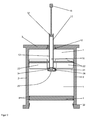
- FIG. 1 shows a schematic cross-sectional view of a device according to the invention.
- the device has a first container 1 with a cylindrical interior, which is filled with a first component of a PMMA bone cement or fillable.
- the first container 1 contains a pasty mass, in which the monomer is methyl methacrylate.
- the first container 1 is bounded laterally by the walls 2 of a cylindrical plastic body.
- the first container 1 is bounded by a cylindrical discharge piston 4.
- the first container 1 is on the front (in FIG. 1 Above) bounded by a volume compensation element 6 in the form of a cylindrical piston.
- the discharge piston 4 and the volume compensation piston 6 are in the direction of the cylinder axis (in FIG. 1 from top to bottom) movable within the walls 2 arranged and sealed gas-tight against the walls 2 by means of O-rings as seals 8.
- a passage is provided with a guide sleeve 10 through which a cylindrical discharge tube 12 extends.
- the dispensing tube 12 has a first end extending into the interior of the first container 1 and an opposite second end having a dispensing opening, via which a ready-mixed cement dough can be applied.
- the discharge tube 12 is arranged along the cylinder axis and rotatable about the cylinder axis movable in the volume balance piston 6 and the guide sleeve 10.
- the discharge tube 12 is closed in its interior by a leachable core 14.
- the core 14 is connected to a handle 16 via a rod extending through the discharge tube 12 and the discharge opening.
- the rod is in the schematic FIG. 1 shown shortened and is actually at least as long that the core 14 can be pushed through to the first end of the discharge tube 12 in order to insert the contents of the discharge tube 12 below in the first container 1 can.
- a further cylindrical disc is provided on the rod between the core and the handle 16, which serves to support and stabilize the movement of the rod in the discharge tube 12. With the handle 16, the discharge tube 12 can be moved through the guide sleeve 10 and thus the discharge tube 12 within the first container 1.
- a second container 18 is arranged in the discharge tube 12, which on the back (in FIG. 1 bottom) is closed by a closure 20 in the form of a plug 20.
- a second component of the bone cement is contained or fillable there.
- the second component is a pasty mass or powder. The second component results in radical hardening of the bone cement when mixed with the first component (methyl methacrylate dough).
- mixing vanes 22 are arranged, with which the contents of the first container 1 can be mixed by moving the discharge tube 12 in the guide sleeve 10.
- the mixing blades 22 thus form a mixing device 22 for manual mixing of the contents of the first container 1.
- the mixing blades 22 are present in the manner of a propeller inclined in opposite directions.
- the plug 20 is connected via a curved and tensioned web 24 with the first end of the discharge tube 12.
- the second container 18 can be opened by the core 14 is pushed in the direction of the first container 1 in the discharge tube 12 into it.
- the contents of the second container 18 (the second component) provide pressure on the plug 22 until the plug 22 releases and is tilted or moved away from the opening at the first end of the dispensing tube 12 by the tensioned web 24.
- the two fluid components are contained in the two containers 1, 18 without air inclusions or are introduced there without gas or air inclusions.
- the second component is a powder, gas, preferably a sterile or sterilizing gas, is contained in the interstices.
- the interior of the container 1, 18 is degassed before filling and sterilized. Since there is no gas inside the first container 1, the contents of the first container 1 are incompressible.
- the volume of the contents of the first container 1 then changes as a result of the insertion or withdrawal of the discharge tube 12.
- the volume can be compensated by an axial movement of the volume compensation piston 6 and, if desired and correspondingly constructed, also by an axial movement of the discharge piston 4. As a result, a mixing of the contents of the first container 1 is possible without the contents of the first container 1 exits or air is drawn into the first container 1.
- the outer cylindrical plastic body 2 is closed by a cover 26.
- openings 28 are provided so that air can escape from the space between the cover 26 and the volume balance piston 6.
- the openings 28 can also be omitted so that said gap can act as a gas spring.
- a steel spring 30 is arranged as a restoring element between the cover 26 and the volume compensation piston 6.
- the steel spring 30 helps to push the volume compensation piston 6 back towards the discharge piston 4 when the discharge tube 12 is again out of the first Container 1 is pulled out.
- a locking means may be provided to lock the volume balance piston 6 so that it can not move when filling the first container 1 with the first component. Before the second component is filled in the first container 1 or before the two components are mixed in the first container 1, the locking means can be released manually.
- the rod over which the core 14 is connected to the handle 16 should be long enough (ie longer than in the schematic FIG. 1 and also in the Figures 2 . 3 and 4 shown). This can ensure that the entire contents of the second container 18 can be transferred into the first container 1. With a wiper lip (not shown) provided at the lower edge of the core 14, it can be ensured that the entire contents of the second container 18 can be removed from the discharge tube 12 without residue.
- a locking ring 34 is pushed onto the first end of the discharge tube 12.
- a detent (not shown) on the circlip 34 and a counter catch (not shown) at the discharge tube 12 ensure that the retaining ring 34 can only push further on the first end of the discharge tube 12 and can not unintentionally detach from the first end of the discharge tube 12.
- the retaining ring 34 On one side (in FIG. 1 right), the retaining ring 34 has a strut 36, which bridges a radial recess on the inside of the securing ring 34.
- the web 24, with which the plug 20 is attached to the discharge tube 12, is bent around this strut 36 on the outside.
- the radial recess on the inside of the locking ring 34, which bridges the strut 36, is so wide and so deep that it can receive the web 24 and bend.
- a plurality of extension pins 38 are provided which protrude in the direction of the discharge piston 4 via the first end of the discharge tube 12.
- the locking ring 34 thus has between two extension pins 38 an axial recess in the direction of the discharge piston 4 (in FIG. 1 right), through which the web 24 extends.
- the discharge tube 12 is also moved axially for mixing the two components.
- the dispensing tube 12 is pushed to the dispensing piston 4, the locking ring 34 is pushed onto the dispensing tube 12 until the ends of the extension pins 38 are flush with the first end of the dispensing tube 12.
- the strut 36 slides over the web 24 and turns it over, so that it rests at least partially on the outer wall of the discharge pipe 12 and from its connection to the discharge pipe 12 in the direction of the front of the device (in FIG. 1 above).
- a second counter-detent (not shown) is provided, which engages in the latching of the securing ring 34, so that the securing ring 34 remains in this retracted position. This ensures that the open plug 20 can no longer move to the opening of the discharge tube 12 at its first end and thereby closes the opening or its free cross-section and thus a possible flow into the discharge tube 12 in difficult.
- FIG. 2 shows a schematic cross-sectional view of another device according to the invention in which the discharge piston 4 acts alone as a volume compensation element 4.
- the structure of the device is the same FIG. 2 except for a few details.
- FIG. 2 The device after FIG. 2 has no additional volume balance piston and no lid. Instead, the plastic body 2 is simply on the front (in FIG. 2 The volume compensation by the insertion and withdrawal of the discharge tube 12 takes place here exclusively by an axial movement of the discharge piston 4. On a spring element as a return element has been omitted in this embodiment.
- the locking ring 34 has in this embodiment, no extension pins but present over its walls designed so deep that it even far enough beyond the first end of the dispensing tube 12 so that it can be pushed by pressing the discharge tube 12 to the discharge piston 4 and characterized the web 24 is pressed against the discharge tube 12 and the plug 20 is secured.
- the axial recess in the locking ring 34 extends in this case into the walls of the securing ring 34.
- a radial recess on the inner circumference of the locking ring 34 is present.
- the remaining strut 36 which closes the securing ring 34 at this point, is raised above the outer circumference of the remaining securing ring 34 and, as in the exemplary embodiment FIG. 1 adapted to bend the web 24 and thereby keep the plug 20 from the opening of the discharge tube 12 at the first end.
- the discharge piston 4 is sealed gas-tight in the present case with two seals 8 against the walls 2.
- FIG. 1 For all other reference numerals to the description FIG. 1 directed.
- FIG. 3 shows a perspective view of a device according to the invention with a volume compensation element 56 on the front (top) and FIG. 4 shows an enlarged view of a partial view of the perspective view after FIG. 3
- the in the Figures 3 and 4 shown device for storage, mixing and application of polymethyl methacrylate bone cement has a first container 51st with a cylindrical interior bounded by transparent walls 52.
- the discharge piston 54 and the volume balance piston 56 are along the cylinder axis (in the Figures 3 and 4 from top to bottom) movably arranged in the interior of the first container 51 and sealed with a circumferential seal 58 against the inner wall of the first container 51.
- the front of the first container 51 is closed with a lid 76.
- a discharge pipe 62 which extends from the interior of the first container 51 to the front and there opens into a discharge opening.
- a core in the Figures 3 and 4 not seen
- the core is attached to the tip of a rod 64, at the other end a handle 66 is attached.
- the handle 66 With the help of the handle 66, the core is movable in the interior of the discharge tube 62.
- a union nut 67 the discharge pipe 62 can be fixed against the cover 76 and released. Otherwise, the discharge pipe 62 is movable in the longitudinal direction and rotatably supported relative to the first container 51.
- a detent 68 extends through an opening in the cover 76 to the volume balance piston 56. Via a hook 69 and a corresponding mating counter-detent on the lock 68, the lock 68 is fixed against the cover 76, so that the volume balance piston 56 is not in the direction of the lid 76 or even not at all relative to the cover 76 and thus to the walls 52 can be moved. Via a handle 70 of the lock 68, the counter-locking of the lock 68 can be released from the hook 69 of the lid 76 and then removed. The volume balance piston 56 is then fully movable against the lid 76 again. The locking of the volume compensation piston 56 serves to move during filling of the first container 51 with the first component and during evacuation and Sterilize the first container 51 to prevent and facilitate these operations.
- the inside of the first container 51 facing side of the discharge tube 62 is closed with a closure 71.
- This end (also referred to as the first end) of the discharge pipe 62 is formed by a short sleeve which is fixedly connected to the remaining discharge pipe 62.
- Four mixing blades 72 which can be moved by movement of the discharge tube 62 in the interior of the first container 51 and which serve as mixing means 72 for the contents of the first container 51, are attached to this sleeve.
- the closure 71 is connected via a flexible, resilient, prestressed web 74 with the sleeve and thus with the discharge pipe 62.
- the closure 71 pushes out of the end of the dispensing tube 62 and is pushed by the web 74, which is a straight shape (in the relaxed state). strives to move away from the opening. Subsequently, the contents of the second container can be transferred by propelling the core into the first container 51.
- an elastic spring 80 is disposed around the discharge tube 62 around, which produces a certain distance between the volume balance piston 56 and the lid 76 in the force-free state.
- a locking ring 84 is plugged as a securing element on the inwardly facing first end of the discharge tube 62 and the sleeve and locked there.
- the web 74 is bent around a strut 86 of the locking ring 84, which in the individual view FIG. 5 can be seen.
- the mixing device 72 By means of the mixing device 72, the two components can be mixed in the interior of the first container 51. To achieve a sufficient mix, the mixing device 72 must be actuated in the entire volume of the first container 51 and thus moved by pulling out and pushing in the discharge tube 62. In this case, the volume of the contents of the first container 51 will change. This volume change is accommodated by movement of the volume balance piston 56 because the components in the cement mix are incompressible and there is no gas or very little gas in the cement mix.
- the first end of the discharge tube 62 is pressed onto the discharge piston 58, and thus the securing ring 84 is further pushed out of the discharge tube 62.
- the web 74 is pushed away by means of the strut 86 of the opening of the discharge tube 62 and thus also the closure 71. This ensures that the closure 71 does not interfere later on the discharge of the cement mixture.
- the ready mixed cement mixture is expelled from the first container 51 by the discharge piston 54 is pressed in the direction of the lid 76. This can be done with a suitable extrusion gun and / or compressed air. Previously, the discharge tube 62 is pulled forward as far as possible from the first container 51, so that the mixing vanes 72 bear against the inside of the volume compensation piston 56, and the core is pulled out of the discharge tube with the aid of the handle 66 and thus the device is opened.
- a device according to the invention is thus a cement cartridge for storing, mixing and applying a two-component cement.
- FIG. 5 shows a perspective view of the inside of the first container 51 facing the end of the discharge tube 62 with a separately arranged locking ring 84.
- the retaining ring 84 (in FIG. 5 Above) has an axial recess 88 and a radial recess 90, which are bridged by the strut 86.
- two grooves 92 or grooves 92 are arranged, which serve as a counter-detent for a locking means 94 on the outer wall of the discharge pipe 62.
- the end of the dispensing tube 62 (or the sleeve) has on the underside an axial recess 96 into which the web 74 can lie when the Closure 71, the opening of the discharge tube 62 closes.
- the web 74 is relaxed.
- the locking ring 84 with respect to in FIG. 5 Orientation shown rotated perpendicular to the axis of symmetry by 180 ° and plugged onto the first end of the discharge tube 62 shown from below until the locking means 94 engages in the first accessible groove 92.
- the strut 86 then rests on the web 74.
- a suitable indexing of the first end of the dispensing tube 62 and the locking ring 84 may be provided. Subsequently, the closure 71 is folded over by 180 ° and inserted into the opening of the discharge tube 62. In this case, the flexible elastic web 74 is bent around the strut 86 around. Then the results in the Figures 3 and 4 shown state of the device.
- the essential structures after the FIGS. 1 to 5 can be manufactured simply and cost-effectively with plastic injection molding technology.
- spring elements or springs steel springs are preferably used.
- the fillings of the first container 1 and the second container 18 are of course not made of plastic but of the starting components of the medical cement.
Landscapes
- Chemical Kinetics & Catalysis (AREA)
- Chemical & Material Sciences (AREA)
- Health & Medical Sciences (AREA)
- Engineering & Computer Science (AREA)
- Orthopedic Medicine & Surgery (AREA)
- Surgery (AREA)
- Life Sciences & Earth Sciences (AREA)
- Medical Informatics (AREA)
- Biomedical Technology (AREA)
- Heart & Thoracic Surgery (AREA)
- Nuclear Medicine, Radiotherapy & Molecular Imaging (AREA)
- Molecular Biology (AREA)
- Animal Behavior & Ethology (AREA)
- General Health & Medical Sciences (AREA)
- Public Health (AREA)
- Veterinary Medicine (AREA)
- Mechanical Engineering (AREA)
- Prostheses (AREA)
- Medical Preparation Storing Or Oral Administration Devices (AREA)
- Materials For Medical Uses (AREA)
Applications Claiming Priority (1)
| Application Number | Priority Date | Filing Date | Title |
|---|---|---|---|
| DE102013226118.7A DE102013226118B3 (de) | 2013-12-16 | 2013-12-16 | Vorrichtung zum Lagern und Mischen von Knochenzement |
Publications (2)
| Publication Number | Publication Date |
|---|---|
| EP2883603A1 true EP2883603A1 (fr) | 2015-06-17 |
| EP2883603B1 EP2883603B1 (fr) | 2016-07-06 |
Family
ID=51730413
Family Applications (1)
| Application Number | Title | Priority Date | Filing Date |
|---|---|---|---|
| EP14189353.7A Not-in-force EP2883603B1 (fr) | 2013-12-16 | 2014-10-17 | Dispositif de stockage et de mélange de ciment osseux |
Country Status (7)
| Country | Link |
|---|---|
| US (1) | US9901380B2 (fr) |
| EP (1) | EP2883603B1 (fr) |
| JP (1) | JP5893120B2 (fr) |
| CN (1) | CN104707519B (fr) |
| AU (1) | AU2014256326B2 (fr) |
| CA (1) | CA2868897C (fr) |
| DE (1) | DE102013226118B3 (fr) |
Cited By (2)
| Publication number | Priority date | Publication date | Assignee | Title |
|---|---|---|---|---|
| EP2902098A1 (fr) * | 2014-02-03 | 2015-08-05 | Heraeus Medical GmbH | Dispositif et procédé de stockage et de mélange de ciment osseux |
| CN111729590A (zh) * | 2020-07-06 | 2020-10-02 | 李雅瑞 | 一种带有混料功能的化妆品生产用下料系统 |
Families Citing this family (18)
| Publication number | Priority date | Publication date | Assignee | Title |
|---|---|---|---|---|
| US9211670B1 (en) * | 2013-03-11 | 2015-12-15 | Galomb, Inc. | Support apparatus for injection tube assembly |
| CN105055012B (zh) * | 2015-08-13 | 2018-09-14 | 广州爱锘德医疗器械有限公司 | 骨水泥搅拌注射器 |
| DE102016110561A1 (de) | 2016-06-08 | 2017-12-14 | Heraeus Medical Gmbh | Lager- und Mischvorrichtung zur Herstellung eines Knochenzements |
| KR20180047956A (ko) * | 2016-11-02 | 2018-05-10 | 주식회사 갈렙 | 본시멘트 자동 믹싱장치 |
| DE102017113126A1 (de) | 2017-06-14 | 2018-12-20 | Heraeus Medical Gmbh | Knochenzementapplikator mit Leitungselement und Verschlussaufnahme |
| US11358109B2 (en) | 2017-08-04 | 2022-06-14 | Mark Robert Towler | Storage, mixing and dispensing device |
| DE102017125592B4 (de) | 2017-11-02 | 2019-06-19 | Heraeus Medical Gmbh | Pulver-Flüssigkeits-Knochenzementmischer mit Druckgasanschluss |
| US10856923B2 (en) | 2018-01-22 | 2020-12-08 | Warsaw Orthopedic, Inc. | Manual mixer |
| CN109480995B (zh) * | 2018-10-29 | 2021-02-12 | 于跃强 | 一种植骨装置 |
| DE102018131268B4 (de) * | 2018-12-07 | 2021-11-25 | Heraeus Medical Gmbh | Vorrichtung zum Mischen eines Knochenzements mit Hohlraum zum Monomertransfer |
| DE102019104020A1 (de) * | 2019-02-18 | 2020-08-20 | Heraeus Medical Gmbh | Knochenzementapplikator mit klemmbarem Austragskolben |
| CN112823862A (zh) * | 2019-11-20 | 2021-05-21 | 中国商用飞机有限责任公司 | 一种手动混胶装置 |
| CN113021640A (zh) * | 2021-04-13 | 2021-06-25 | 华能洋浦热电有限公司 | 一种混凝土搅拌混合装置 |
| JP7270308B1 (ja) | 2022-03-07 | 2023-05-10 | 株式会社サイエンス | バブル液発生器 |
| CN115556237B (zh) * | 2022-08-31 | 2026-01-16 | 浙江精匠建材有限公司 | 一种环保加气混凝土砌块的制造方法及专用搅拌机 |
| CN116423873A (zh) * | 2023-06-09 | 2023-07-14 | 四川爱思达航天科技有限公司 | 一种碳纤维复合材料的成型工艺及装置 |
| US20250072463A1 (en) * | 2023-08-30 | 2025-03-06 | Sharkninja Operating Llc | Plunger retention assembly for a micro-puree machine |
| CN120420870B (zh) * | 2025-07-08 | 2025-10-21 | 东莞信易电热机械有限公司 | 一种真空式原料混匀装置 |
Citations (10)
| Publication number | Priority date | Publication date | Assignee | Title |
|---|---|---|---|---|
| US3144966A (en) * | 1962-04-16 | 1964-08-18 | Semco Res Inc | Cartridge for mixing and dispensing sealant compound |
| DE2808230A1 (de) * | 1978-02-25 | 1979-08-30 | Korte Jungermann Ges Fuer Fass | Spritz-kartusche |
| WO1989005763A1 (fr) * | 1987-12-24 | 1989-06-29 | Upat Gmbh & Co. | Cartouche d'injection |
| WO2007053870A2 (fr) * | 2005-11-08 | 2007-05-18 | Gerhard Bonecker | Procede de mesure photometrique pour un echantillon liquide, systeme de mesure photometrique et reservoir de melange pour un systeme de mesure photometrique |
| DE102007052116A1 (de) | 2007-10-22 | 2009-04-23 | Heraeus Medical Gmbh | Einkomponenten-Knochenzementpasten und Verfahren zu deren Aushärtung |
| DE102007050762B3 (de) | 2007-10-22 | 2009-05-07 | Heraeus Medical Gmbh | Pastenförmiger Polymethylmethacrylat-Knochenzement und seine Verwendung |
| DE102008030312A1 (de) | 2008-06-30 | 2010-01-14 | Heraeus Medical Gmbh | PMMA-Paste |
| EP2072114B1 (fr) | 2007-12-19 | 2011-01-05 | Heraeus Medical GmbH | Dispositif destiné à mélanger du ciment osseux |
| EP2596812A1 (fr) | 2011-11-22 | 2013-05-29 | Heraeus Medical GmbH | Stérilisation de monomères polymérisables |
| EP2823881A1 (fr) * | 2013-07-08 | 2015-01-14 | Heraeus Medical GmbH | Dispositif et procédé de stockage et de mélange de ciment osseux |
Family Cites Families (12)
| Publication number | Priority date | Publication date | Assignee | Title |
|---|---|---|---|---|
| CA1113894A (fr) | 1978-01-07 | 1981-12-08 | Hans W. Korte-Jungermann | Cartouche d'injection |
| US4463875A (en) * | 1982-06-14 | 1984-08-07 | Robert W. Mann | Method and apparatus for preparing and applying a two-component cement |
| US5123927A (en) | 1990-12-05 | 1992-06-23 | University Of British Columbia | Method and apparatus for antibiotic knee prothesis |
| DK0861117T3 (da) * | 1995-11-13 | 2001-10-22 | Cemvac System Ab | Fremgangsmåde og indretning til blanding af bestanddele til knoglecement i et blandekar |
| US6155812A (en) | 1998-07-15 | 2000-12-05 | Biomet, Inc | Cement mold for a temporary implant |
| SE524714C2 (sv) * | 2002-06-28 | 2004-09-21 | Asept Medical Ab | Beredare och applikator för bencement |
| GB2411849B (en) * | 2004-03-08 | 2007-08-29 | Summit Medical Ltd | Apparatus for mixing and discharging bone cement |
| SE527528C2 (sv) * | 2004-06-22 | 2006-04-04 | Bone Support Ab | Anordning för framställning av härdbar massa samt användning av anordningen |
| DE102007063613B4 (de) | 2007-04-24 | 2010-01-07 | Heraeus Kulzer Gmbh | Verwendung eines Spacer-Polymethylmethacrylat-Knochenzement |
| US8480289B2 (en) | 2008-08-22 | 2013-07-09 | Biomet Manufacturing, Llc | Bone cement mixing cartridge and method of use |
| CA2742050C (fr) | 2008-10-29 | 2014-11-25 | Scott M. Sporer | Moule d'espacement avec fixation amovible |
| CN102019152B (zh) * | 2009-09-22 | 2013-02-13 | 中央医疗器材股份有限公司 | 一种骨科用混合灌出装置 |
-
2013
- 2013-12-16 DE DE102013226118.7A patent/DE102013226118B3/de not_active Expired - Fee Related
-
2014
- 2014-10-17 EP EP14189353.7A patent/EP2883603B1/fr not_active Not-in-force
- 2014-10-23 CA CA2868897A patent/CA2868897C/fr not_active Expired - Fee Related
- 2014-10-28 AU AU2014256326A patent/AU2014256326B2/en not_active Ceased
- 2014-12-16 JP JP2014253850A patent/JP5893120B2/ja not_active Expired - Fee Related
- 2014-12-16 CN CN201410774720.3A patent/CN104707519B/zh not_active Expired - Fee Related
- 2014-12-16 US US14/571,356 patent/US9901380B2/en not_active Expired - Fee Related
Patent Citations (10)
| Publication number | Priority date | Publication date | Assignee | Title |
|---|---|---|---|---|
| US3144966A (en) * | 1962-04-16 | 1964-08-18 | Semco Res Inc | Cartridge for mixing and dispensing sealant compound |
| DE2808230A1 (de) * | 1978-02-25 | 1979-08-30 | Korte Jungermann Ges Fuer Fass | Spritz-kartusche |
| WO1989005763A1 (fr) * | 1987-12-24 | 1989-06-29 | Upat Gmbh & Co. | Cartouche d'injection |
| WO2007053870A2 (fr) * | 2005-11-08 | 2007-05-18 | Gerhard Bonecker | Procede de mesure photometrique pour un echantillon liquide, systeme de mesure photometrique et reservoir de melange pour un systeme de mesure photometrique |
| DE102007052116A1 (de) | 2007-10-22 | 2009-04-23 | Heraeus Medical Gmbh | Einkomponenten-Knochenzementpasten und Verfahren zu deren Aushärtung |
| DE102007050762B3 (de) | 2007-10-22 | 2009-05-07 | Heraeus Medical Gmbh | Pastenförmiger Polymethylmethacrylat-Knochenzement und seine Verwendung |
| EP2072114B1 (fr) | 2007-12-19 | 2011-01-05 | Heraeus Medical GmbH | Dispositif destiné à mélanger du ciment osseux |
| DE102008030312A1 (de) | 2008-06-30 | 2010-01-14 | Heraeus Medical Gmbh | PMMA-Paste |
| EP2596812A1 (fr) | 2011-11-22 | 2013-05-29 | Heraeus Medical GmbH | Stérilisation de monomères polymérisables |
| EP2823881A1 (fr) * | 2013-07-08 | 2015-01-14 | Heraeus Medical GmbH | Dispositif et procédé de stockage et de mélange de ciment osseux |
Cited By (3)
| Publication number | Priority date | Publication date | Assignee | Title |
|---|---|---|---|---|
| EP2902098A1 (fr) * | 2014-02-03 | 2015-08-05 | Heraeus Medical GmbH | Dispositif et procédé de stockage et de mélange de ciment osseux |
| US10010362B2 (en) | 2014-02-03 | 2018-07-03 | Heraeus Medical Gmbh | Device for storing and mixing bone cement |
| CN111729590A (zh) * | 2020-07-06 | 2020-10-02 | 李雅瑞 | 一种带有混料功能的化妆品生产用下料系统 |
Also Published As
| Publication number | Publication date |
|---|---|
| DE102013226118B3 (de) | 2015-06-11 |
| US20150164568A1 (en) | 2015-06-18 |
| JP2015119966A (ja) | 2015-07-02 |
| EP2883603B1 (fr) | 2016-07-06 |
| CN104707519B (zh) | 2017-10-03 |
| CA2868897A1 (fr) | 2015-06-16 |
| CN104707519A (zh) | 2015-06-17 |
| AU2014256326A1 (en) | 2015-07-02 |
| JP5893120B2 (ja) | 2016-03-23 |
| AU2014256326B2 (en) | 2016-07-14 |
| CA2868897C (fr) | 2017-01-03 |
| US9901380B2 (en) | 2018-02-27 |
Similar Documents
| Publication | Publication Date | Title |
|---|---|---|
| EP2883603B1 (fr) | Dispositif de stockage et de mélange de ciment osseux | |
| EP2823881B1 (fr) | Dispositif et procédé de stockage et de mélange de ciment osseux | |
| EP2902098B1 (fr) | Dispositif et procédé de stockage et de mélange de ciment osseux | |
| EP2730332B1 (fr) | Dispositif de mélange et d'extraction d'une masse pâteuse | |
| EP2384820B1 (fr) | Système de cartouche et tuyau de sortie pour un tel système de cartouche | |
| DE102015116797B4 (de) | Vorrichtung und Verfahren zum Lagern und Mischen eines Knochenzements | |
| EP2457531B1 (fr) | Cartouche dotée de pistons de transport pouvant être bloqués | |
| DE102014113816B3 (de) | Pasten-Applikationssystem zum Lagern zweier Ausgangskomponenten, zum Mischen der Ausgangskomponenten zu einer Paste und zum Applizieren der Paste sowie Verfahren zum Mischen und Austreiben einer Paste | |
| DE102014109905B4 (de) | Vakuummischsystem und Verfahren zum Mischen von Polymethylmethacrylat-Knochenzement | |
| EP3216408B1 (fr) | Système de stockage et de mélange pour composants de ciment pâteux et procédé associé | |
| EP0493363A2 (fr) | Dispositif et procédé pour mélanger et transvaser un mélange de matières visqueuses | |
| EP3272300B1 (fr) | Applicateur de ciment osseux à l'aide d'une vanne trois voies destinée à la décharge de pression | |
| EP3216516B1 (fr) | Système de stockage et de mélange pour composants de ciment pâteux et procédé associé | |
| DE102016110564A1 (de) | Lager- und Mischvorrichtung für Knochenzement mit Druckpumpe | |
| DE102016113468A1 (de) | Knochenzement-Applikator mit Dreiwege-Ventil zur Druckentlastung | |
| EP3219274A2 (fr) | Système de stockage et de mélange pour composants de ciment pâteux | |
| EP3415226A1 (fr) | Applicateur de ciment osseux pourvu d'élément conducteur et logement de fermeture | |
| DE102016107911A1 (de) | Lagerungs- und Mischsystem für pastenförmige Ausgangskomponenten mit auspressbarer Innenkartusche | |
| DE20022899U1 (de) | Vorrichtung mit einem dicht abgeschlossenen, flüssigkeits-, pasten- oder gasgefüllten Behältnis und mit Mitteln zum Austragen des Behältnisinhalts | |
| EP2072114B1 (fr) | Dispositif destiné à mélanger du ciment osseux | |
| EP3695797B1 (fr) | Applicateur de ciment osseux pourvu de piston de décharge pouvant être serré |
Legal Events
| Date | Code | Title | Description |
|---|---|---|---|
| PUAI | Public reference made under article 153(3) epc to a published international application that has entered the european phase |
Free format text: ORIGINAL CODE: 0009012 |
|
| 17P | Request for examination filed |
Effective date: 20141017 |
|
| AK | Designated contracting states |
Kind code of ref document: A1 Designated state(s): AL AT BE BG CH CY CZ DE DK EE ES FI FR GB GR HR HU IE IS IT LI LT LU LV MC MK MT NL NO PL PT RO RS SE SI SK SM TR |
|
| AX | Request for extension of the european patent |
Extension state: BA ME |
|
| GRAP | Despatch of communication of intention to grant a patent |
Free format text: ORIGINAL CODE: EPIDOSNIGR1 |
|
| RIC1 | Information provided on ipc code assigned before grant |
Ipc: B01F 11/00 20060101AFI20160219BHEP Ipc: B01F 15/02 20060101ALI20160219BHEP Ipc: B01F 13/00 20060101ALI20160219BHEP |
|
| INTG | Intention to grant announced |
Effective date: 20160310 |
|
| GRAS | Grant fee paid |
Free format text: ORIGINAL CODE: EPIDOSNIGR3 |
|
| GRAA | (expected) grant |
Free format text: ORIGINAL CODE: 0009210 |
|
| AK | Designated contracting states |
Kind code of ref document: B1 Designated state(s): AL AT BE BG CH CY CZ DE DK EE ES FI FR GB GR HR HU IE IS IT LI LT LU LV MC MK MT NL NO PL PT RO RS SE SI SK SM TR |
|
| REG | Reference to a national code |
Ref country code: GB Ref legal event code: FG4D Free format text: NOT ENGLISH |
|
| REG | Reference to a national code |
Ref country code: AT Ref legal event code: REF Ref document number: 810300 Country of ref document: AT Kind code of ref document: T Effective date: 20160715 Ref country code: CH Ref legal event code: EP |
|
| REG | Reference to a national code |
Ref country code: IE Ref legal event code: FG4D Free format text: LANGUAGE OF EP DOCUMENT: GERMAN |
|
| REG | Reference to a national code |
Ref country code: DE Ref legal event code: R096 Ref document number: 502014001049 Country of ref document: DE |
|
| REG | Reference to a national code |
Ref country code: NL Ref legal event code: FP |
|
| REG | Reference to a national code |
Ref country code: SE Ref legal event code: TRGR |
|
| REG | Reference to a national code |
Ref country code: FR Ref legal event code: PLFP Year of fee payment: 3 |
|
| REG | Reference to a national code |
Ref country code: LT Ref legal event code: MG4D |
|
| REG | Reference to a national code |
Ref country code: NO Ref legal event code: T2 Effective date: 20160706 |
|
| PG25 | Lapsed in a contracting state [announced via postgrant information from national office to epo] |
Ref country code: RS Free format text: LAPSE BECAUSE OF FAILURE TO SUBMIT A TRANSLATION OF THE DESCRIPTION OR TO PAY THE FEE WITHIN THE PRESCRIBED TIME-LIMIT Effective date: 20160706 Ref country code: LT Free format text: LAPSE BECAUSE OF FAILURE TO SUBMIT A TRANSLATION OF THE DESCRIPTION OR TO PAY THE FEE WITHIN THE PRESCRIBED TIME-LIMIT Effective date: 20160706 Ref country code: IS Free format text: LAPSE BECAUSE OF FAILURE TO SUBMIT A TRANSLATION OF THE DESCRIPTION OR TO PAY THE FEE WITHIN THE PRESCRIBED TIME-LIMIT Effective date: 20161106 Ref country code: HR Free format text: LAPSE BECAUSE OF FAILURE TO SUBMIT A TRANSLATION OF THE DESCRIPTION OR TO PAY THE FEE WITHIN THE PRESCRIBED TIME-LIMIT Effective date: 20160706 Ref country code: IT Free format text: LAPSE BECAUSE OF FAILURE TO SUBMIT A TRANSLATION OF THE DESCRIPTION OR TO PAY THE FEE WITHIN THE PRESCRIBED TIME-LIMIT Effective date: 20160706 Ref country code: FI Free format text: LAPSE BECAUSE OF FAILURE TO SUBMIT A TRANSLATION OF THE DESCRIPTION OR TO PAY THE FEE WITHIN THE PRESCRIBED TIME-LIMIT Effective date: 20160706 |
|
| PG25 | Lapsed in a contracting state [announced via postgrant information from national office to epo] |
Ref country code: PT Free format text: LAPSE BECAUSE OF FAILURE TO SUBMIT A TRANSLATION OF THE DESCRIPTION OR TO PAY THE FEE WITHIN THE PRESCRIBED TIME-LIMIT Effective date: 20161107 Ref country code: PL Free format text: LAPSE BECAUSE OF FAILURE TO SUBMIT A TRANSLATION OF THE DESCRIPTION OR TO PAY THE FEE WITHIN THE PRESCRIBED TIME-LIMIT Effective date: 20160706 Ref country code: BE Free format text: LAPSE BECAUSE OF NON-PAYMENT OF DUE FEES Effective date: 20161031 Ref country code: LV Free format text: LAPSE BECAUSE OF FAILURE TO SUBMIT A TRANSLATION OF THE DESCRIPTION OR TO PAY THE FEE WITHIN THE PRESCRIBED TIME-LIMIT Effective date: 20160706 Ref country code: GR Free format text: LAPSE BECAUSE OF FAILURE TO SUBMIT A TRANSLATION OF THE DESCRIPTION OR TO PAY THE FEE WITHIN THE PRESCRIBED TIME-LIMIT Effective date: 20161007 Ref country code: ES Free format text: LAPSE BECAUSE OF FAILURE TO SUBMIT A TRANSLATION OF THE DESCRIPTION OR TO PAY THE FEE WITHIN THE PRESCRIBED TIME-LIMIT Effective date: 20160706 |
|
| REG | Reference to a national code |
Ref country code: DE Ref legal event code: R097 Ref document number: 502014001049 Country of ref document: DE |
|
| PG25 | Lapsed in a contracting state [announced via postgrant information from national office to epo] |
Ref country code: RO Free format text: LAPSE BECAUSE OF FAILURE TO SUBMIT A TRANSLATION OF THE DESCRIPTION OR TO PAY THE FEE WITHIN THE PRESCRIBED TIME-LIMIT Effective date: 20160706 Ref country code: EE Free format text: LAPSE BECAUSE OF FAILURE TO SUBMIT A TRANSLATION OF THE DESCRIPTION OR TO PAY THE FEE WITHIN THE PRESCRIBED TIME-LIMIT Effective date: 20160706 |
|
| PLBE | No opposition filed within time limit |
Free format text: ORIGINAL CODE: 0009261 |
|
| STAA | Information on the status of an ep patent application or granted ep patent |
Free format text: STATUS: NO OPPOSITION FILED WITHIN TIME LIMIT |
|
| PG25 | Lapsed in a contracting state [announced via postgrant information from national office to epo] |
Ref country code: DK Free format text: LAPSE BECAUSE OF FAILURE TO SUBMIT A TRANSLATION OF THE DESCRIPTION OR TO PAY THE FEE WITHIN THE PRESCRIBED TIME-LIMIT Effective date: 20160706 Ref country code: CZ Free format text: LAPSE BECAUSE OF FAILURE TO SUBMIT A TRANSLATION OF THE DESCRIPTION OR TO PAY THE FEE WITHIN THE PRESCRIBED TIME-LIMIT Effective date: 20160706 Ref country code: BG Free format text: LAPSE BECAUSE OF FAILURE TO SUBMIT A TRANSLATION OF THE DESCRIPTION OR TO PAY THE FEE WITHIN THE PRESCRIBED TIME-LIMIT Effective date: 20161006 Ref country code: SM Free format text: LAPSE BECAUSE OF FAILURE TO SUBMIT A TRANSLATION OF THE DESCRIPTION OR TO PAY THE FEE WITHIN THE PRESCRIBED TIME-LIMIT Effective date: 20160706 Ref country code: SK Free format text: LAPSE BECAUSE OF FAILURE TO SUBMIT A TRANSLATION OF THE DESCRIPTION OR TO PAY THE FEE WITHIN THE PRESCRIBED TIME-LIMIT Effective date: 20160706 |
|
| 26N | No opposition filed |
Effective date: 20170407 |
|
| REG | Reference to a national code |
Ref country code: IE Ref legal event code: MM4A |
|
| PG25 | Lapsed in a contracting state [announced via postgrant information from national office to epo] |
Ref country code: LU Free format text: LAPSE BECAUSE OF NON-PAYMENT OF DUE FEES Effective date: 20161017 Ref country code: SI Free format text: LAPSE BECAUSE OF FAILURE TO SUBMIT A TRANSLATION OF THE DESCRIPTION OR TO PAY THE FEE WITHIN THE PRESCRIBED TIME-LIMIT Effective date: 20160706 |
|
| REG | Reference to a national code |
Ref country code: FR Ref legal event code: PLFP Year of fee payment: 4 |
|
| PG25 | Lapsed in a contracting state [announced via postgrant information from national office to epo] |
Ref country code: IE Free format text: LAPSE BECAUSE OF NON-PAYMENT OF DUE FEES Effective date: 20161017 |
|
| REG | Reference to a national code |
Ref country code: BE Ref legal event code: MM Effective date: 20161031 |
|
| REG | Reference to a national code |
Ref country code: DE Ref legal event code: R082 Ref document number: 502014001049 Country of ref document: DE Representative=s name: BRAND, NORMEN, DR. RER. NAT., DE Ref country code: DE Ref legal event code: R082 Ref document number: 502014001049 Country of ref document: DE Representative=s name: BRAND, NORMEN, DIPL.-CHEM. UNIV. DR. RER. NAT., DE Ref country code: DE Ref legal event code: R082 Ref document number: 502014001049 Country of ref document: DE Representative=s name: EULER, MATTHIAS, DR., DE |
|
| PG25 | Lapsed in a contracting state [announced via postgrant information from national office to epo] |
Ref country code: HU Free format text: LAPSE BECAUSE OF FAILURE TO SUBMIT A TRANSLATION OF THE DESCRIPTION OR TO PAY THE FEE WITHIN THE PRESCRIBED TIME-LIMIT; INVALID AB INITIO Effective date: 20141017 |
|
| PG25 | Lapsed in a contracting state [announced via postgrant information from national office to epo] |
Ref country code: CY Free format text: LAPSE BECAUSE OF FAILURE TO SUBMIT A TRANSLATION OF THE DESCRIPTION OR TO PAY THE FEE WITHIN THE PRESCRIBED TIME-LIMIT Effective date: 20160706 Ref country code: MK Free format text: LAPSE BECAUSE OF FAILURE TO SUBMIT A TRANSLATION OF THE DESCRIPTION OR TO PAY THE FEE WITHIN THE PRESCRIBED TIME-LIMIT Effective date: 20160706 Ref country code: MT Free format text: LAPSE BECAUSE OF FAILURE TO SUBMIT A TRANSLATION OF THE DESCRIPTION OR TO PAY THE FEE WITHIN THE PRESCRIBED TIME-LIMIT Effective date: 20160706 Ref country code: MC Free format text: LAPSE BECAUSE OF FAILURE TO SUBMIT A TRANSLATION OF THE DESCRIPTION OR TO PAY THE FEE WITHIN THE PRESCRIBED TIME-LIMIT Effective date: 20160706 |
|
| REG | Reference to a national code |
Ref country code: FR Ref legal event code: PLFP Year of fee payment: 5 |
|
| PG25 | Lapsed in a contracting state [announced via postgrant information from national office to epo] |
Ref country code: AL Free format text: LAPSE BECAUSE OF FAILURE TO SUBMIT A TRANSLATION OF THE DESCRIPTION OR TO PAY THE FEE WITHIN THE PRESCRIBED TIME-LIMIT Effective date: 20160706 Ref country code: TR Free format text: LAPSE BECAUSE OF FAILURE TO SUBMIT A TRANSLATION OF THE DESCRIPTION OR TO PAY THE FEE WITHIN THE PRESCRIBED TIME-LIMIT Effective date: 20160706 |
|
| PGFP | Annual fee paid to national office [announced via postgrant information from national office to epo] |
Ref country code: NL Payment date: 20181019 Year of fee payment: 5 |
|
| PGFP | Annual fee paid to national office [announced via postgrant information from national office to epo] |
Ref country code: SE Payment date: 20181019 Year of fee payment: 5 Ref country code: NO Payment date: 20181024 Year of fee payment: 5 |
|
| PGFP | Annual fee paid to national office [announced via postgrant information from national office to epo] |
Ref country code: CH Payment date: 20181019 Year of fee payment: 5 |
|
| REG | Reference to a national code |
Ref country code: DE Ref legal event code: R082 Ref document number: 502014001049 Country of ref document: DE Representative=s name: BRAND, NORMEN, DR. RER. NAT., DE Ref country code: DE Ref legal event code: R082 Ref document number: 502014001049 Country of ref document: DE Representative=s name: BRAND, NORMEN, DIPL.-CHEM. UNIV. DR. RER. NAT., DE |
|
| PGFP | Annual fee paid to national office [announced via postgrant information from national office to epo] |
Ref country code: FR Payment date: 20191028 Year of fee payment: 6 |
|
| PGFP | Annual fee paid to national office [announced via postgrant information from national office to epo] |
Ref country code: GB Payment date: 20191021 Year of fee payment: 6 |
|
| REG | Reference to a national code |
Ref country code: NO Ref legal event code: MMEP |
|
| REG | Reference to a national code |
Ref country code: CH Ref legal event code: PL |
|
| REG | Reference to a national code |
Ref country code: NL Ref legal event code: MM Effective date: 20191101 |
|
| PG25 | Lapsed in a contracting state [announced via postgrant information from national office to epo] |
Ref country code: NO Free format text: LAPSE BECAUSE OF NON-PAYMENT OF DUE FEES Effective date: 20191031 Ref country code: LI Free format text: LAPSE BECAUSE OF NON-PAYMENT OF DUE FEES Effective date: 20191031 Ref country code: CH Free format text: LAPSE BECAUSE OF NON-PAYMENT OF DUE FEES Effective date: 20191031 |
|
| PG25 | Lapsed in a contracting state [announced via postgrant information from national office to epo] |
Ref country code: NL Free format text: LAPSE BECAUSE OF NON-PAYMENT OF DUE FEES Effective date: 20191101 Ref country code: SE Free format text: LAPSE BECAUSE OF NON-PAYMENT OF DUE FEES Effective date: 20191018 |
|
| REG | Reference to a national code |
Ref country code: AT Ref legal event code: MM01 Ref document number: 810300 Country of ref document: AT Kind code of ref document: T Effective date: 20191017 |
|
| PG25 | Lapsed in a contracting state [announced via postgrant information from national office to epo] |
Ref country code: AT Free format text: LAPSE BECAUSE OF NON-PAYMENT OF DUE FEES Effective date: 20191017 |
|
| GBPC | Gb: european patent ceased through non-payment of renewal fee |
Effective date: 20201017 |
|
| PG25 | Lapsed in a contracting state [announced via postgrant information from national office to epo] |
Ref country code: FR Free format text: LAPSE BECAUSE OF NON-PAYMENT OF DUE FEES Effective date: 20201031 |
|
| PG25 | Lapsed in a contracting state [announced via postgrant information from national office to epo] |
Ref country code: GB Free format text: LAPSE BECAUSE OF NON-PAYMENT OF DUE FEES Effective date: 20201017 |
|
| REG | Reference to a national code |
Ref country code: DE Ref legal event code: R079 Ref document number: 502014001049 Country of ref document: DE Free format text: PREVIOUS MAIN CLASS: B01F0011000000 Ipc: B01F0031000000 |
|
| PGFP | Annual fee paid to national office [announced via postgrant information from national office to epo] |
Ref country code: DE Payment date: 20221019 Year of fee payment: 9 |
|
| P01 | Opt-out of the competence of the unified patent court (upc) registered |
Effective date: 20230527 |
|
| REG | Reference to a national code |
Ref country code: DE Ref legal event code: R119 Ref document number: 502014001049 Country of ref document: DE |
|
| PG25 | Lapsed in a contracting state [announced via postgrant information from national office to epo] |
Ref country code: DE Free format text: LAPSE BECAUSE OF NON-PAYMENT OF DUE FEES Effective date: 20240501 |