EP2883692B1 - Dispositif et procédé de liaison de pièces en tôle et d'un paquet de tôles - Google Patents
Dispositif et procédé de liaison de pièces en tôle et d'un paquet de tôles Download PDFInfo
- Publication number
- EP2883692B1 EP2883692B1 EP14197506.0A EP14197506A EP2883692B1 EP 2883692 B1 EP2883692 B1 EP 2883692B1 EP 14197506 A EP14197506 A EP 14197506A EP 2883692 B1 EP2883692 B1 EP 2883692B1
- Authority
- EP
- European Patent Office
- Prior art keywords
- sheet
- separating
- metal
- metal strip
- sheet metal
- Prior art date
- Legal status (The legal status is an assumption and is not a legal conclusion. Google has not performed a legal analysis and makes no representation as to the accuracy of the status listed.)
- Active
Links
Images




Classifications
-
- C—CHEMISTRY; METALLURGY
- C21—METALLURGY OF IRON
- C21D—MODIFYING THE PHYSICAL STRUCTURE OF FERROUS METALS; GENERAL DEVICES FOR HEAT TREATMENT OF FERROUS OR NON-FERROUS METALS OR ALLOYS; MAKING METAL MALLEABLE, e.g. BY DECARBURISATION OR TEMPERING
- C21D8/00—Modifying the physical properties of ferrous metals or ferrous alloys by deformation combined with, or followed by, heat treatment
- C21D8/12—Modifying the physical properties of ferrous metals or ferrous alloys by deformation combined with, or followed by, heat treatment during manufacturing of articles with special electromagnetic properties
- C21D8/1277—Modifying the physical properties of ferrous metals or ferrous alloys by deformation combined with, or followed by, heat treatment during manufacturing of articles with special electromagnetic properties involving a particular surface treatment
-
- B—PERFORMING OPERATIONS; TRANSPORTING
- B32—LAYERED PRODUCTS
- B32B—LAYERED PRODUCTS, i.e. PRODUCTS BUILT-UP OF STRATA OF FLAT OR NON-FLAT, e.g. CELLULAR OR HONEYCOMB, FORM
- B32B7/00—Layered products characterised by the relation between layers; Layered products characterised by the relative orientation of features between layers, or by the relative values of a measurable parameter between layers, i.e. products comprising layers having different physical, chemical or physicochemical properties; Layered products characterised by the interconnection of layers
- B32B7/04—Interconnection of layers
- B32B7/12—Interconnection of layers using interposed adhesives or interposed materials with bonding properties
-
- B—PERFORMING OPERATIONS; TRANSPORTING
- B32—LAYERED PRODUCTS
- B32B—LAYERED PRODUCTS, i.e. PRODUCTS BUILT-UP OF STRATA OF FLAT OR NON-FLAT, e.g. CELLULAR OR HONEYCOMB, FORM
- B32B15/00—Layered products comprising a layer of metal
- B32B15/04—Layered products comprising a layer of metal comprising metal as the main or only constituent of a layer, which is next to another layer of the same or of a different material
- B32B15/08—Layered products comprising a layer of metal comprising metal as the main or only constituent of a layer, which is next to another layer of the same or of a different material of synthetic resin
-
- B—PERFORMING OPERATIONS; TRANSPORTING
- B32—LAYERED PRODUCTS
- B32B—LAYERED PRODUCTS, i.e. PRODUCTS BUILT-UP OF STRATA OF FLAT OR NON-FLAT, e.g. CELLULAR OR HONEYCOMB, FORM
- B32B23/00—Layered products comprising a layer of cellulosic plastic substances, i.e. substances obtained by chemical modification of cellulose, e.g. cellulose ethers, cellulose esters, viscose
- B32B23/04—Layered products comprising a layer of cellulosic plastic substances, i.e. substances obtained by chemical modification of cellulose, e.g. cellulose ethers, cellulose esters, viscose comprising such cellulosic plastic substance as the main or only constituent of a layer, which is next to another layer of the same or of a different material
- B32B23/042—Layered products comprising a layer of cellulosic plastic substances, i.e. substances obtained by chemical modification of cellulose, e.g. cellulose ethers, cellulose esters, viscose comprising such cellulosic plastic substance as the main or only constituent of a layer, which is next to another layer of the same or of a different material of metal
-
- B—PERFORMING OPERATIONS; TRANSPORTING
- B32—LAYERED PRODUCTS
- B32B—LAYERED PRODUCTS, i.e. PRODUCTS BUILT-UP OF STRATA OF FLAT OR NON-FLAT, e.g. CELLULAR OR HONEYCOMB, FORM
- B32B23/00—Layered products comprising a layer of cellulosic plastic substances, i.e. substances obtained by chemical modification of cellulose, e.g. cellulose ethers, cellulose esters, viscose
- B32B23/22—Layered products comprising a layer of cellulosic plastic substances, i.e. substances obtained by chemical modification of cellulose, e.g. cellulose ethers, cellulose esters, viscose comprising ethers
-
- B—PERFORMING OPERATIONS; TRANSPORTING
- B32—LAYERED PRODUCTS
- B32B—LAYERED PRODUCTS, i.e. PRODUCTS BUILT-UP OF STRATA OF FLAT OR NON-FLAT, e.g. CELLULAR OR HONEYCOMB, FORM
- B32B27/00—Layered products comprising a layer of synthetic resin
- B32B27/16—Layered products comprising a layer of synthetic resin specially treated, e.g. irradiated
-
- B—PERFORMING OPERATIONS; TRANSPORTING
- B32—LAYERED PRODUCTS
- B32B—LAYERED PRODUCTS, i.e. PRODUCTS BUILT-UP OF STRATA OF FLAT OR NON-FLAT, e.g. CELLULAR OR HONEYCOMB, FORM
- B32B27/00—Layered products comprising a layer of synthetic resin
- B32B27/30—Layered products comprising a layer of synthetic resin comprising vinyl (co)polymers; comprising acrylic (co)polymers
- B32B27/306—Layered products comprising a layer of synthetic resin comprising vinyl (co)polymers; comprising acrylic (co)polymers comprising vinyl acetate or vinyl alcohol (co)polymers
-
- B—PERFORMING OPERATIONS; TRANSPORTING
- B32—LAYERED PRODUCTS
- B32B—LAYERED PRODUCTS, i.e. PRODUCTS BUILT-UP OF STRATA OF FLAT OR NON-FLAT, e.g. CELLULAR OR HONEYCOMB, FORM
- B32B37/00—Methods or apparatus for laminating, e.g. by curing or by ultrasonic bonding
- B32B37/14—Methods or apparatus for laminating, e.g. by curing or by ultrasonic bonding characterised by the properties of the layers
- B32B37/16—Methods or apparatus for laminating, e.g. by curing or by ultrasonic bonding characterised by the properties of the layers with all layers existing as coherent layers before laminating
- B32B37/18—Methods or apparatus for laminating, e.g. by curing or by ultrasonic bonding characterised by the properties of the layers with all layers existing as coherent layers before laminating involving the assembly of discrete sheets or panels only
-
- B—PERFORMING OPERATIONS; TRANSPORTING
- B32—LAYERED PRODUCTS
- B32B—LAYERED PRODUCTS, i.e. PRODUCTS BUILT-UP OF STRATA OF FLAT OR NON-FLAT, e.g. CELLULAR OR HONEYCOMB, FORM
- B32B38/00—Ancillary operations in connection with laminating processes
- B32B38/0004—Cutting, tearing or severing, e.g. bursting; Cutter details
-
- B—PERFORMING OPERATIONS; TRANSPORTING
- B32—LAYERED PRODUCTS
- B32B—LAYERED PRODUCTS, i.e. PRODUCTS BUILT-UP OF STRATA OF FLAT OR NON-FLAT, e.g. CELLULAR OR HONEYCOMB, FORM
- B32B7/00—Layered products characterised by the relation between layers; Layered products characterised by the relative orientation of features between layers, or by the relative values of a measurable parameter between layers, i.e. products comprising layers having different physical, chemical or physicochemical properties; Layered products characterised by the interconnection of layers
- B32B7/04—Interconnection of layers
- B32B7/06—Interconnection of layers permitting easy separation
-
- H—ELECTRICITY
- H01—ELECTRIC ELEMENTS
- H01F—MAGNETS; INDUCTANCES; TRANSFORMERS; SELECTION OF MATERIALS FOR THEIR MAGNETIC PROPERTIES
- H01F3/00—Cores, Yokes, or armatures
- H01F3/02—Cores, Yokes, or armatures made from sheets
-
- H—ELECTRICITY
- H01—ELECTRIC ELEMENTS
- H01F—MAGNETS; INDUCTANCES; TRANSFORMERS; SELECTION OF MATERIALS FOR THEIR MAGNETIC PROPERTIES
- H01F41/00—Apparatus or processes specially adapted for manufacturing or assembling magnets, inductances or transformers; Apparatus or processes specially adapted for manufacturing materials characterised by their magnetic properties
- H01F41/02—Apparatus or processes specially adapted for manufacturing or assembling magnets, inductances or transformers; Apparatus or processes specially adapted for manufacturing materials characterised by their magnetic properties for manufacturing cores, coils, or magnets
- H01F41/0206—Manufacturing of magnetic cores by mechanical means
- H01F41/0233—Manufacturing of magnetic circuits made from sheets
-
- H—ELECTRICITY
- H02—GENERATION; CONVERSION OR DISTRIBUTION OF ELECTRIC POWER
- H02K—DYNAMO-ELECTRIC MACHINES
- H02K1/00—Details of the magnetic circuit
- H02K1/04—Details of the magnetic circuit characterised by the material used for insulating the magnetic circuit or parts thereof
-
- H—ELECTRICITY
- H02—GENERATION; CONVERSION OR DISTRIBUTION OF ELECTRIC POWER
- H02K—DYNAMO-ELECTRIC MACHINES
- H02K15/00—Processes or apparatus specially adapted for manufacturing, assembling, maintaining or repairing of dynamo-electric machines
- H02K15/02—Processes or apparatus specially adapted for manufacturing, assembling, maintaining or repairing of dynamo-electric machines of stator or rotor bodies
-
- B—PERFORMING OPERATIONS; TRANSPORTING
- B32—LAYERED PRODUCTS
- B32B—LAYERED PRODUCTS, i.e. PRODUCTS BUILT-UP OF STRATA OF FLAT OR NON-FLAT, e.g. CELLULAR OR HONEYCOMB, FORM
- B32B2255/00—Coating on the layer surface
- B32B2255/26—Polymeric coating
-
- B—PERFORMING OPERATIONS; TRANSPORTING
- B32—LAYERED PRODUCTS
- B32B—LAYERED PRODUCTS, i.e. PRODUCTS BUILT-UP OF STRATA OF FLAT OR NON-FLAT, e.g. CELLULAR OR HONEYCOMB, FORM
- B32B2307/00—Properties of the layers or laminate
- B32B2307/50—Properties of the layers or laminate having particular mechanical properties
- B32B2307/54—Yield strength; Tensile strength
-
- B—PERFORMING OPERATIONS; TRANSPORTING
- B32—LAYERED PRODUCTS
- B32B—LAYERED PRODUCTS, i.e. PRODUCTS BUILT-UP OF STRATA OF FLAT OR NON-FLAT, e.g. CELLULAR OR HONEYCOMB, FORM
- B32B2307/00—Properties of the layers or laminate
- B32B2307/70—Other properties
- B32B2307/748—Releasability
-
- B—PERFORMING OPERATIONS; TRANSPORTING
- B32—LAYERED PRODUCTS
- B32B—LAYERED PRODUCTS, i.e. PRODUCTS BUILT-UP OF STRATA OF FLAT OR NON-FLAT, e.g. CELLULAR OR HONEYCOMB, FORM
- B32B2311/00—Metals, their alloys or their compounds
-
- B—PERFORMING OPERATIONS; TRANSPORTING
- B32—LAYERED PRODUCTS
- B32B—LAYERED PRODUCTS, i.e. PRODUCTS BUILT-UP OF STRATA OF FLAT OR NON-FLAT, e.g. CELLULAR OR HONEYCOMB, FORM
- B32B2457/00—Electrical equipment
-
- C—CHEMISTRY; METALLURGY
- C21—METALLURGY OF IRON
- C21D—MODIFYING THE PHYSICAL STRUCTURE OF FERROUS METALS; GENERAL DEVICES FOR HEAT TREATMENT OF FERROUS OR NON-FERROUS METALS OR ALLOYS; MAKING METAL MALLEABLE, e.g. BY DECARBURISATION OR TEMPERING
- C21D8/00—Modifying the physical properties of ferrous metals or ferrous alloys by deformation combined with, or followed by, heat treatment
- C21D8/12—Modifying the physical properties of ferrous metals or ferrous alloys by deformation combined with, or followed by, heat treatment during manufacturing of articles with special electromagnetic properties
-
- C—CHEMISTRY; METALLURGY
- C21—METALLURGY OF IRON
- C21D—MODIFYING THE PHYSICAL STRUCTURE OF FERROUS METALS; GENERAL DEVICES FOR HEAT TREATMENT OF FERROUS OR NON-FERROUS METALS OR ALLOYS; MAKING METAL MALLEABLE, e.g. BY DECARBURISATION OR TEMPERING
- C21D8/00—Modifying the physical properties of ferrous metals or ferrous alloys by deformation combined with, or followed by, heat treatment
- C21D8/12—Modifying the physical properties of ferrous metals or ferrous alloys by deformation combined with, or followed by, heat treatment during manufacturing of articles with special electromagnetic properties
- C21D8/1277—Modifying the physical properties of ferrous metals or ferrous alloys by deformation combined with, or followed by, heat treatment during manufacturing of articles with special electromagnetic properties involving a particular surface treatment
- C21D8/1283—Application of a separating or insulating coating
-
- H—ELECTRICITY
- H01—ELECTRIC ELEMENTS
- H01F—MAGNETS; INDUCTANCES; TRANSFORMERS; SELECTION OF MATERIALS FOR THEIR MAGNETIC PROPERTIES
- H01F1/00—Magnets or magnetic bodies characterised by the magnetic materials therefor; Selection of materials for their magnetic properties
- H01F1/01—Magnets or magnetic bodies characterised by the magnetic materials therefor; Selection of materials for their magnetic properties of inorganic materials
- H01F1/03—Magnets or magnetic bodies characterised by the magnetic materials therefor; Selection of materials for their magnetic properties of inorganic materials characterised by their coercivity
- H01F1/12—Magnets or magnetic bodies characterised by the magnetic materials therefor; Selection of materials for their magnetic properties of inorganic materials characterised by their coercivity of soft-magnetic materials
- H01F1/14—Magnets or magnetic bodies characterised by the magnetic materials therefor; Selection of materials for their magnetic properties of inorganic materials characterised by their coercivity of soft-magnetic materials metals or alloys
- H01F1/16—Magnets or magnetic bodies characterised by the magnetic materials therefor; Selection of materials for their magnetic properties of inorganic materials characterised by their coercivity of soft-magnetic materials metals or alloys in the form of sheets
- H01F1/18—Magnets or magnetic bodies characterised by the magnetic materials therefor; Selection of materials for their magnetic properties of inorganic materials characterised by their coercivity of soft-magnetic materials metals or alloys in the form of sheets with insulating coating
-
- H—ELECTRICITY
- H02—GENERATION; CONVERSION OR DISTRIBUTION OF ELECTRIC POWER
- H02K—DYNAMO-ELECTRIC MACHINES
- H02K15/00—Processes or apparatus specially adapted for manufacturing, assembling, maintaining or repairing of dynamo-electric machines
- H02K15/12—Impregnating, moulding insulation, heating or drying of windings, stators, rotors or machines
-
- Y—GENERAL TAGGING OF NEW TECHNOLOGICAL DEVELOPMENTS; GENERAL TAGGING OF CROSS-SECTIONAL TECHNOLOGIES SPANNING OVER SEVERAL SECTIONS OF THE IPC; TECHNICAL SUBJECTS COVERED BY FORMER USPC CROSS-REFERENCE ART COLLECTIONS [XRACs] AND DIGESTS
- Y10—TECHNICAL SUBJECTS COVERED BY FORMER USPC
- Y10T—TECHNICAL SUBJECTS COVERED BY FORMER US CLASSIFICATION
- Y10T156/00—Adhesive bonding and miscellaneous chemical manufacture
- Y10T156/10—Methods of surface bonding and/or assembly therefor
- Y10T156/1052—Methods of surface bonding and/or assembly therefor with cutting, punching, tearing or severing
- Y10T156/1062—Prior to assembly
-
- Y—GENERAL TAGGING OF NEW TECHNOLOGICAL DEVELOPMENTS; GENERAL TAGGING OF CROSS-SECTIONAL TECHNOLOGIES SPANNING OVER SEVERAL SECTIONS OF THE IPC; TECHNICAL SUBJECTS COVERED BY FORMER USPC CROSS-REFERENCE ART COLLECTIONS [XRACs] AND DIGESTS
- Y10—TECHNICAL SUBJECTS COVERED BY FORMER USPC
- Y10T—TECHNICAL SUBJECTS COVERED BY FORMER US CLASSIFICATION
- Y10T428/00—Stock material or miscellaneous articles
- Y10T428/31504—Composite [nonstructural laminate]
- Y10T428/31678—Of metal
Definitions
- the invention relates to a method for connecting sheet metal parts to form a laminated core, in which sheet metal parts are separated from a sheet metal strip, in particular electrical steel, with an at least regionally curable, polymer adhesive layer, in particular baking varnish, using a separating device, which separated sheet metal parts are provided one above the other in a stack brake be connected at least materially to form a plurality of laminated cores, with a parting agent being applied in certain areas to the adhesive layer of the laminated strip in such a way that after the separation of a sheet metal part coated with it, this sheet metal part facilitates the separation of the laminated cores.
- any impurities in the separation device can be bound by the separating agent and thus reduce the reproducibility of the process.
- an exact width dimension of the laminated cores often a necessary prerequisite for electrical machines, for example to be able to comply with air gap dimensions or recesses for permanent magnets. Such component dimensions cannot be reliably guaranteed with a release agent adhering to the front side.
- the invention has therefore set itself the task of creating an easy-to-use method, based on the prior art described at the outset, with which sheet metal parts can be reproducibly connected to dimensionally accurate, mechanically strong and yet easily separable sheet stacks.
- the invention solves the problem set by the features of claim 1.
- the method can initially be characterized by improved simplicity.
- the separating agent is namely applied to the sheet metal strip before separating steps of the separating device take place, in order to gradually prepare the sheet metal strip for the final severing of a sheet metal part. Therefore, at the time of the separating coating, the contours or the essential contours of the sheet metal part to be separated are not yet provided on the sheet metal strip - which means that there is no need for the separating layer to be applied to the laminated core following the contours. Tolerances during the subsequent processing of the sheet metal strip are therefore irrelevant for the release coating - so that the process is particularly reproducible.
- the separating agent applied to the sheet metal strip upstream of the separating device can bind any impurities in the separating device, preferably to those cutting residues that are separated from the sheet metal strip before the sheet metal part is finally severed.
- the separating device can thus be kept free from contamination, which can ensure reproducible dimensionally accurate and mechanically strong laminated cores.
- applying separating agent upstream of the separating device can, according to the invention, avoid an undesired application of separating agent to the face of the sheet metal part to be separated, which avoids widening of the laminated cores or electrical laminated cores.
- the method according to the invention can therefore not only enable simple separation of the laminated cores leaving the laminated brake - it can also ensure according to the invention that the laminated cores, which are always dimensionally accurate and mechanically strong, in particular electrical laminated cores, for electrical machines or electrical or electromagnetic applications are particularly suitable.
- the cutting device can have one or more tools with which the sheet metal strip is processed.
- a tool can have one or more cutting edges for cutting out or cutting off the sheet metal strip in order to form the sheet metal part for the laminated core.
- the separating device has a pusher as a tool in order to detach a sheet metal part that has been cut out from the sheet metal strip during the final separation or to disassemble the sheet metal strip in this regard.
- a separating agent is applied to both sides of the sheet metal strip directly opposite one another, a sheet metal part with a release coating on both sides can be created, which acts as a spacer between the laminations and ensures easier separation of the laminations.
- the laminated cores can be produced free of a release coating, which can further increase the reproducibility of the process.
- a release coating can be produced on the first and last sheet metal part of a laminated core.
- this can facilitate the conditions for removing the separating coating if necessary, it being conceivable that these end-side separating coatings remain on the laminated core and lead to a functional added value of the laminated core.
- the technical effect of the separating agent can be intensified if the separating coating is applied in such a way that the separating coating completely covers the adhesive layer after the sheet metal part has been finally separated off. Sticking of the stacks of laminations to one another can thus be effectively avoided even with increased pressures in the stack brake, which can have a positive effect on the reproducibility of the process.
- a release film is laminated on as the release agent, the handling of the method can be further simplified.
- a separating film can on the one hand serve to protect the sheet metal parts, preferably as edge protection, and on the other hand improve the protection against short circuits of electrical windings or coils on the laminated core.
- an adhesive label is preferably laminated on, known methods for applying adhesive labels can be used, which can further increase the simplicity and reproducibility of the method. In general, it is mentioned that a self-adhesive adhesive label with a non-stick coating can be particularly suitable for the method.
- this separating film can cover any punching burrs and thus ensure that the laminated core is free of burrs.
- separating film is applied to the adhesive layer using a roller application process
- continuous rolls of the separating film, in particular of the adhesive labels can be used—simple in terms of process technology. This enables continuous lamination and ensures short cycle times when cutting off sheet metal parts.
- a separating liquid is applied to the adhesive layer as a separating agent and dried in front of the separating device, an alternative method to laminating a separating film can be created for the separating coating of the metal strip.
- the drying step can prevent the separating liquid from running down unfavorably and penetrating into undesired areas of the adhesive layer. In addition, it can thus be avoided that the cutting edges or punches of the separating device are not contaminated with the separating liquid.
- a particularly effective coating for separating laminated cores can be produced if a separating liquid containing polytetrafluoroethylene (PTFE) is applied to the adhesive layer, since PTFE has particularly excellent non-stick properties and sliding properties.
- PTFE polytetrafluoroethylene
- the separating liquid can be dried by supplying heat. This can be done directly or indirectly, for example by means of hot air, infrared radiation, inductive heating or with a heated tool of the separating device.
- the separating liquid can be applied by a spraying or printing process in a technically simple manner.
- a template can be used to define the coating area of the release agent.
- all common printing methods in particular pad printing, gravure printing or screen printing, can be used to apply the release liquid to the adhesive layer.
- the sheet metal strip can be prepared for easier end cutting of the sheet metal parts if the cutting device according to the invention pre-separates parts from the sheet metal strip and then finish-severs the sheet metal part from the sheet metal strip.
- the separating device can also have any number of further separating steps in addition to a preliminary separating and a final separating.
- the invention has also set itself the task of creating a device for connecting sheet metal parts to form a laminated core which, with a simple design, can reliably produce laminated cores which can be reliably separated from one another and have a high degree of dimensional accuracy.
- the invention solves the problem set by the features of claim 10.
- the coating device is provided in front of the separating device, this not only simplifies the construction of the device, but also ensures that the separating agent of the coating device cannot adversely affect the structural width dimensions of the sheet metal part and thus the laminated core. This is because the separating coating is also separated by the separating device in accordance with the sheet metal part to be separated, which can prevent the separating coating from protruding at the end. According to the invention, a dimensionally accurate laminated core can thus be made possible.
- the dimensional accuracy of the separated sheet metal part or of the sheet metal bundles can be increased if the separating device according to the invention has a plurality of cutting edges for pre-separation and final separation on the sheet-metal strip.
- several separation steps can support the process in terms of protecting the tools, which can increase the stability of the device and the dimensional accuracy of the laminated core.
- the coating device has a label dispenser for dispensing adhesive labels onto the metal strip as a release agent, the construction of the device can be further simplified.
- label dispensers can ensure a continuous process and increase the stability of the device due to their reliability.
- a self-adhesive adhesive label with a non-stick coating can be particularly suitable as a release agent or release coating.
- the coating device has at least one spray nozzle for spraying or at least one coating roller for printing a release liquid in order to reliably provide the metal strip with a release coating.
- a device 1 is shown, for example, with which the method according to the invention for connecting sheet metal parts 2 to form a laminated core 3 is carried out.
- a sheet metal strip 5 is unwound from a coil 4, which strip has a full-surface polymeric adhesive layer 8, preferably a baked lacquer, on one or both strip sides 6, 7.
- a separating device 10 several sheet metal parts 2, for which the separating device 10 includes an upper tool 11 and a lower tool 12.
- Such a severing of the severing device 10 can generally be stamping or cutting out, cutting off, notching, trimming, dividing by pressing etc.
- the severing device 10 is divided into a preliminary severing with a cutting edge 13 and a final severing with a cutting edge 14 of the upper tool 11, which cutting edges 13, 14 each interact with matrices that are not described in more detail.
- parts 15 or cutting residues that are not required are removed from the sheet metal strip 5 in order to prepare the sheet metal strip 5 for a final cutting of the sheet metal part 2, as is also the case in FIG 2 can be recognized more closely.
- the sheet metal parts 2 are cut out and pushed by the pressure of the upper tool 11 into a partially tapering guide in the lower tool 12, which exerts the effect of a stack brake 16 on the sheet stack and thus connects the sheet metal parts 2 to form stacks 3.
- a counter-holder in the guide is also conceivable, which exerts a corresponding counter-pressure for connecting the sheet metal parts 2, which has not been shown in detail.
- the separated sheet metal parts 2 form a firm physical and/or chemical bond under the pressure of the upper tool 11 and with the help of the polymer adhesive layer 8 present between the sheet metal parts.
- the package brake 16 can also be actively heated in order to improve the material connection of the sheet metal parts 2.
- the laminated cores 3 can be subjected to further hardening steps that are not shown in detail, in order to strengthen the bonded connection between the sheet metal parts.
- a separating agent 18 is applied to predefined sheet metal parts 2 using a coating device 9 .
- the coating device 9 has two coating rollers 17, 18, each of which acts on one strip side 6, 7 of the sheet metal strip 5. With the help of these coating rollers 17, 18, a parting agent 19 is applied in some areas to the metal strip 5 in order to form a parting coating 20 in sections on it.
- this coating device 9 is provided before the separating device 10 . This increases the reproducibility of the method and simplifies the construction of the device 1, as can be seen from FIG 2 is explained in more detail.
- a release coating 20 is applied to the metal strip 5 at most in certain areas using the coating roller 17 .
- the separating coating 20 is always reliably limited to those desired areas 31 that belong to a sheet metal part 2 to be punched out, which is to be separating coated and thus facilitates the separating of the laminated cores 3 .
- Other areas 32 of the sheet metal strip 5 remain free of the separating coating 20 in order not to jeopardize the joining of the sheet metal parts 2 to form a laminated core 3 .
- the partially parting-coated sheet metal strip 5 then runs to the parting device 10 .
- a part 15 or cutting residue that is not required is punched out or cut out with a preliminary cutting with a blade 13 in order to prepare the sheet metal strip 5 for the final cutting.
- the preliminary separation can also have several separation steps, which is not shown in more detail in the figures.
- the desired sheet metal part 2 is then cut off from the sheet metal strip 5, resulting in 2 shown forms a segment of a layer of the laminated core 3 and is completely covered with a release coating 20 .
- the sheet metal parts 2 are only pressed out of the sheet metal strip 5 during the final cutting, in which the upper tool 11 for the final cutting does not have a cutting edge 14 but rather a pressing tool that is not shown in detail.
- the sheet metal part 2 can be cut in front of this pressing tool in a preliminary separation, the sheet metal part 2 being pushed back into the sheet metal strip 5 and then finally separated from the sheet metal strip 5 by the pressing tool.
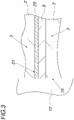
- FIG. 3 an exemplary layer structure of sheet metal parts 2 connected to form a laminated core 3 in the package brake 16 is shown.
- a separating coating 20 is provided between two laminated cores 3 .
- This release coating 20 was applied to the polymer adhesive layer 8 of the top sheet metal part 2 of the laminated core 3, which is in this figure 3 located under the other laminated core 3. This makes it easier to separate the laminated cores 3 shown here when they leave the core brake 16 .
- a laminated core 3 is processed with a one-sided adhesive coating 20 is in 4 the processing of a sheet metal strip 5 coated with adhesive on both sides is shown in more detail.
- the easier separation of the laminated cores 3 is made possible here by a sheet metal part 2 with a release coating on both sides, the adhesive coatings 8 of which are each covered with a release coating 20 .
- the sheet metal part 2 is thus not part of a laminated core 3 and is removed from the latter as a separating sheet metal part 21 after the laminated cores 3 have been separated.
- the laminated cores 3 separated in this way are therefore advantageously free from residues of the separating coating.
- a separating sheet metal part 21 can also be made possible with a sheet metal part 2 coated on one side, in which case a separating layer 20 is directly connected to the sheet metal part 2 .
- the separating coatings 20 are each applied over the entire surface of the polymeric adhesive layers 8, which leads to a particularly simple separation of the laminated core 3.
- the release coating 20 can first be applied to one or both polymeric adhesive layers 20 of the sheet metal strip 5 in such a way that a sheet metal part 2 coated over the entire surface with release agent 19 is separated during the final separation 14 .
- This will be according to 2 made possible by a projection of the separating coating 20 over the contour of the sheet metal part 2 to be finally separated, in order to ensure that a continuous, full-surface separating coating 20 on the sheet metal parts 2 is ensured in the event of any manufacturing tolerances.
- the coating device 9 uses a release film 22 as the release agent 19 , in particular in the form of an adhesive label 22 .
- Self-adhesive adhesive labels 22 with a non-stick coating are preferably used.
- the adhesive labels 22 are laminated onto one side or both sides of the coated metal strip 5 and thus form the separating coating 20 . As already mentioned, this protrudes from the contour of the sheet metal part 2 to be cut off at the end.
- An adhesive label 22 can be applied, for example, using known methods for dispensing, which enables short cycle times.
- the adhesive labels 22 are laminated onto the polymeric adhesive layer 8 of one or both sides 6, 7 of the tape using a partially shown label dispenser 30.
- continuous release films 22 on rolls can be used.
- these adhesive labels 22 can also be laminated on with vertically movable laminating stamps 23. This makes it possible, in particular, for adhesive labels 22 to be laminated onto the sheet metal strip 5 over the entire surface in one step.
- a separating liquid 24 is used as the separating agent 19 in the application process of the coating device 9 .
- a dispersion containing polytetrafluoroethylene (PTFE) can be used here as the separating liquid 24 .
- the PTFE particles can significantly improve the non-stick property of the separating liquid 24 .
- the release liquid 24 is dried after it has been applied to one or more polymeric adhesive layers.
- a hot-air dryer 25 or other drying methods 26 by heating the sheet-metal strip 5 are optionally used for this purpose.
- the sheet metal strip 5 can be heated directly with an induction heater 26 and the separating liquid 24 for forming the separating coating 20 can thereby be dried.
- the separating liquid 24 is sprayed onto the metal strip 5 through a template 28 with the aid of a spray nozzle 27 .
- the template is used for the targeted application of separating liquid 24 in the desired areas.
- the separating liquid 24 can also be carried out using any common printing process, such as pad printing, gravure printing or screen printing, which is 7 has not been detailed.
Landscapes
- Engineering & Computer Science (AREA)
- Power Engineering (AREA)
- Manufacturing & Machinery (AREA)
- Chemical & Material Sciences (AREA)
- Physics & Mathematics (AREA)
- Mechanical Engineering (AREA)
- Thermal Sciences (AREA)
- Crystallography & Structural Chemistry (AREA)
- Electromagnetism (AREA)
- Materials Engineering (AREA)
- Metallurgy (AREA)
- Organic Chemistry (AREA)
- Laminated Bodies (AREA)
- Adhesives Or Adhesive Processes (AREA)
- Dispersion Chemistry (AREA)
- Manufacturing Cores, Coils, And Magnets (AREA)
Claims (13)
- Procédé pour l'assemblage de pièces de tôle (2) en paquets de tôles (3), dans lequel des pièces de tôle (2) sont découpées dans un feuillard de tôle (5), en particulier un feuillard magnétique, avec au moins par zones une couche d'adhésif (8) polymère durcissable, en particulier de vernis thermodurcissable, au moyen d'un dispositif de découpe (10), lequel dispositif de découpe (10) prédécoupe des pièces (15) du feuillard de tôle (5) et finit la découpe de la pièce de tôle (2) du feuillard de tôle (5), les pièces de tôle (2) découpées étant superposées dans une pile de freinage des paquets (16) et assemblés au moins par solidarité de matière pour former plusieurs paquets de tôles (3), procédé dans lequel un agent de séparation (19) est appliqué par zones sur au moins une couche d'adhésif (8) du feuillard de tôle (5) de telle manière qu'après la découpe d'une pièce de tôle (2) ainsi munie du revêtement de séparation, cette pièce de tôle (2) facilite la séparation des paquets de tôles (3), caractérisé en ce que l'agent de séparation (19) est appliqué sur la couche d'adhésif (8) du feuillard de tôle (5) avant le dispositif de découpe (10).
- Procédé selon la revendication 1, caractérisé en ce qu'un agent de séparation (19) est appliqué sur chacun des deux côtés (6, 7) du feuillard de tôle (5) en position directement opposée.
- Procédé selon la revendication 1, caractérisé en ce qu'un agent de séparation (19) est appliqué alternativement sur chacun des deux côtés (6, 7) du feuillard de tôle (5).
- Procédé selon la revendication 1, 2 ou 3, caractérisé en ce que le revêtement de séparation (20) est appliqué de telle façon que le revêtement de séparation (20) recouvre complètement la couche d'adhésif (8) après la découpe finale (14) de la pièce de tôle (2).
- Procédé selon l'une des revendications 1 à 4, caractérisé en ce que l'agent de séparation (19) utilisé est un film de séparation (22), en particulier une étiquette adhésive (22) munie en particulier d'un revêtement antiadhésif, appliqué par stratification.
- Procédé selon la revendication 5, caractérisé en ce que le film de séparation (22) est stratifié sur le côté du feuillard de tôle (6, 7) tourné à l'opposé du poinçon du dispositif de découpe (10).
- Procédé selon la revendication 5 ou 6, caractérisé en ce que le film de séparation (22) est appliqué à l'aide d'un procédé d'application par rouleaux (17, 18) sur la couche d'adhésif (8, 9).
- Procédé selon l'une des revendications 1 à 4, caractérisé en ce que l'agent de séparation (19) utilisé est un liquide de séparation (24), contenant en particulier du polytétrafluoroéthylène, appliqué sur la couche d'adhésif (8) et séché avant le dispositif de découpe (10).
- Procédé selon la revendication 8, caractérisé en ce que le liquide de séparation (24) est appliqué par un procédé de pulvérisation ou d'impression (27).
- Dispositif pour l'assemblage de pièces de tôle (2) en un paquet de tôles (3) avec un feuillard de tôle (5), en particulier un feuillard magnétique, revêtu au moins par zones d'une couche d'adhésif (8) polymère durcissable, en particulier de vernis thermodurcissable, avec au moins un dispositif de découpe (10) pour détacher des pièces de tôle (2) du feuillard de tôle (5), lequel dispositif de découpe (10) présente plusieurs lames (13, 14) pour la prédécoupe et la découpe finale du feuillard de tôle (5), avec une pile de freinage des paquets (16) pour l'assemblage au moins par solidarité de matière des pièces de tôle (2) détachées et superposées pour former un paquet de tôles (3) et avec un dispositif de revêtement (9) qui applique par zones sur au moins une couche d'adhésif (8) du feuillard (5) un agent de séparation (19), de telle façon qu'après la découpe d'une pièce de tôle (2) ainsi munie du revêtement de séparation, cette pièce de tôle (2) facilite la séparation des paquets de tôles (3), caractérisé en ce que le dispositif de revêtement (9) est prévu avant le dispositif de découpe (10) pour appliquer l'agent de séparation (19) sur la couche d'adhésif (8) du feuillard de tôle (5) avant le dispositif de découpe (10).
- Dispositif selon la revendication 10, caractérisé en ce que le revêtement de séparation (20) dépasse du contour de la pièce de tôle (2) à découper.
- Dispositif selon la revendication 10 ou 11, caractérisé en ce que le dispositif de revêtement (9) comprend un distributeur d'étiquettes (30) pour distribuer des étiquettes adhésives (22) servant d'agent de séparation (19) sur le feuillard de tôle (5).
- Dispositif selon la revendication 10 ou 11, caractérisé en ce que le dispositif de revêtement (9) comprend au moins une buse de pulvérisation (27) pour pulvériser un liquide de séparation (24) ou au moins un rouleau de revêtement (17, 18) pour imprimer avec celui-ci.
Priority Applications (1)
| Application Number | Priority Date | Filing Date | Title |
|---|---|---|---|
| SI201432002T SI2883692T1 (sl) | 2012-12-11 | 2014-12-11 | Naprava in postopek za povezovanje pločevinastih delov v paket pločevin |
Applications Claiming Priority (2)
| Application Number | Priority Date | Filing Date | Title |
|---|---|---|---|
| ATA50576/2012A AT512931B1 (de) | 2012-12-11 | 2012-12-11 | Blechpaket und Verfahren zum Verbinden von Blechteilen zu einem Blechpaket |
| PCT/AT2013/050246 WO2014089593A1 (fr) | 2012-12-11 | 2013-12-11 | Noyau feuilleté et procédé pour assembler des pièces de tôle pour former un noyau feuilleté |
Publications (2)
| Publication Number | Publication Date |
|---|---|
| EP2883692A1 EP2883692A1 (fr) | 2015-06-17 |
| EP2883692B1 true EP2883692B1 (fr) | 2022-08-17 |
Family
ID=49919849
Family Applications (2)
| Application Number | Title | Priority Date | Filing Date |
|---|---|---|---|
| EP13820723.8A Active EP2931520B1 (fr) | 2012-12-11 | 2013-12-11 | Noyau feuilleté et procédé pour assembler des pièces de tôle pour former un noyau feuilleté |
| EP14197506.0A Active EP2883692B1 (fr) | 2012-12-11 | 2014-12-11 | Dispositif et procédé de liaison de pièces en tôle et d'un paquet de tôles |
Family Applications Before (1)
| Application Number | Title | Priority Date | Filing Date |
|---|---|---|---|
| EP13820723.8A Active EP2931520B1 (fr) | 2012-12-11 | 2013-12-11 | Noyau feuilleté et procédé pour assembler des pièces de tôle pour former un noyau feuilleté |
Country Status (11)
| Country | Link |
|---|---|
| US (1) | US10391741B2 (fr) |
| EP (2) | EP2931520B1 (fr) |
| JP (1) | JP6548081B2 (fr) |
| KR (1) | KR102211301B1 (fr) |
| CN (2) | CN112937010A (fr) |
| AT (1) | AT512931B1 (fr) |
| HU (1) | HUE060437T4 (fr) |
| MX (1) | MX370378B (fr) |
| PL (1) | PL2883692T3 (fr) |
| SI (1) | SI2883692T1 (fr) |
| WO (1) | WO2014089593A1 (fr) |
Cited By (1)
| Publication number | Priority date | Publication date | Assignee | Title |
|---|---|---|---|---|
| US12319043B2 (en) | 2020-11-11 | 2025-06-03 | Voestalpine Stahl Gmbh | Method for connecting sheet metal parts in order to form lamination stacks |
Families Citing this family (43)
| Publication number | Priority date | Publication date | Assignee | Title |
|---|---|---|---|---|
| AT512931B1 (de) * | 2012-12-11 | 2013-12-15 | Voestalpine Stahl Gmbh | Blechpaket und Verfahren zum Verbinden von Blechteilen zu einem Blechpaket |
| DE102014017149A1 (de) * | 2014-11-17 | 2016-05-19 | Kienle + Spiess Gmbh | Verfahren zur Herstellung von Lamellenpaketen und Anlage zur Durchführung des Verfahrens |
| US10097054B2 (en) * | 2015-01-30 | 2018-10-09 | Honeywell International Inc. | Methods for manufacturing high temperature laminated stator cores |
| EP3072936A1 (fr) | 2015-03-24 | 2016-09-28 | Voestalpine Stahl GmbH | Bobine et bande ou tôle électrique |
| EP3089335B1 (fr) | 2015-04-30 | 2019-02-20 | voestalpine Automotive Components Dettingen GmbH & Co. KG | Dispositif et procédé de liaison de parties de tôles à un paquet de tôles |
| DE102015208870A1 (de) * | 2015-05-13 | 2016-11-17 | Breuckmann GmbH & Co. KG | Verfahren zur Herstellung eines Blechpakets |
| EP3154069A1 (fr) * | 2015-10-07 | 2017-04-12 | STAMPTEC-Holding GmbH | Procede et dispositif de liaison d'elements de tole a des paquets de toles |
| KR101669513B1 (ko) * | 2015-12-08 | 2016-10-27 | 주식회사 포스코티엠씨 | 접착식 적층코어 제조장치 |
| EP3206213A1 (fr) | 2016-02-15 | 2017-08-16 | Voestalpine Stahl GmbH | Procede de passage de bande destine a fabriquer un stratifie de bandes electriques enroulees sur une bobine |
| CN105914030B (zh) * | 2016-04-21 | 2017-11-17 | 广州新莱福磁电有限公司 | 一种铁氧体片材覆膜装置 |
| KR101693155B1 (ko) * | 2016-08-22 | 2017-01-04 | (주)항남 | 적층 코어의 내경 가열이 가능한 적층 코어 제조 장치 |
| EP3316457A1 (fr) * | 2016-10-27 | 2018-05-02 | voestalpine Automotive Components Deutschland GmbH | Dispositif et procédé de liaison de parties de tôles à un paquet de tôles |
| EP3373419A1 (fr) * | 2017-03-09 | 2018-09-12 | voestalpine Automotive Components Deutschland GmbH | Dispositif et procédé de liaison de parties de tôles à un paquet de tôles |
| DE102018110951A1 (de) * | 2017-11-03 | 2019-05-09 | Fraunhofer-Gesellschaft zur Förderung der angewandten Forschung eingetragener Verein | Verfahren zum klebtechnischen Verbinden von Elektroblechen und Elektrobleche hergestellt nach einem entsprechenden Verfahren |
| KR102005634B1 (ko) * | 2017-11-06 | 2019-10-01 | (주)항남 | 스탬프 방식의 접착식 적층 코어 제조 장치 |
| WO2019088616A1 (fr) * | 2017-11-06 | 2019-05-09 | Hangnam Co., Ltd. | Appareil de fabrication d'un noyau de stratification d'adhésif par estampage |
| KR101990291B1 (ko) * | 2017-11-06 | 2019-06-20 | (주)항남 | 스프레이 방식의 접착식 적층 코어 제조 장치 |
| JP6515241B1 (ja) * | 2018-03-02 | 2019-05-15 | 田中精密工業株式会社 | 接着剤塗布装置及び接着剤塗布方法 |
| KR102066460B1 (ko) * | 2018-04-03 | 2020-01-15 | 문쥬리 | 모터 코어용 접착강판의 제조방법 |
| DE102018206151B4 (de) | 2018-04-20 | 2024-12-12 | Voestalpine Stahl Gmbh | Beschichtetes blechband und verfahren zur herstellung |
| EP3569405A1 (fr) | 2018-05-18 | 2019-11-20 | voestalpine Stahl GmbH | Bande ou tôle électrique, procédé de fabrication d'une telle bande ou tôle électrique ainsi qu'empilement de tôles correspondant |
| DE102018122047A1 (de) * | 2018-09-10 | 2020-03-12 | voestalpine Automotive Components Dettingen GmbH & Co. KG | Verfahren und vorrichtung zum verbinden von blechteilen zu blechpaketen |
| US11437188B2 (en) | 2018-09-25 | 2022-09-06 | Honeywell International Inc. | Low porosity glass coatings formed on coiled wires, high temperature devices containing the same, and methods for the fabrication thereof |
| EP3736062A1 (fr) * | 2019-05-08 | 2020-11-11 | voestalpine Stahl GmbH | Procédé d'assemblage par boutonnage d'éléments de tôle à des paquets de tôle |
| DE102019113290A1 (de) * | 2019-05-20 | 2020-11-26 | Thyssenkrupp Steel Europe Ag | Verfahren zum Herstellen einer elektromagnetischen Komponente, insbesondere eines Blechpakets, beispielsweise eines Statorpakets oder eines Rotorpakets, für eine elektrische Maschine |
| DE102019113291A1 (de) * | 2019-05-20 | 2020-11-26 | Thyssenkrupp Steel Europe Ag | Blech für die Herstellung einer elektromagnetischen Komponente, insbesondere eines Statorpakets oder eines Rotorpakets, sowie Verfahren zur Herstellung einer elektromagnetischen Komponente |
| DE102019213658A1 (de) | 2019-09-09 | 2021-03-11 | Elringklinger Ag | Verfahren zur Herstellung eines Blechstapels, Blechstapel, Maschinenbauteil und Elektromotor |
| DE102019213659A1 (de) | 2019-09-09 | 2021-03-11 | Elringklinger Ag | Verfahren zur Herstellung eines Blechstapels, Blechstapel, Maschinenbauteil und Elektromotor |
| DE102019134136B3 (de) * | 2019-12-12 | 2021-04-29 | Voestalpine Stahl Gmbh | Verfahren zur herstellung von beschichteten elektrobändern und beschichtetes elektroband |
| JP7347197B2 (ja) * | 2019-12-19 | 2023-09-20 | トヨタ自動車株式会社 | 回転電機コアの製造方法および製造装置 |
| EP3892467A1 (fr) * | 2020-04-07 | 2021-10-13 | voestalpine Automotive Components Dettingen GmbH & Co. KG | Dispositif et procédé d'assemblage de pièces en tôle en paquets de tôle |
| DE102020109985A1 (de) * | 2020-04-09 | 2021-10-14 | Thyssenkrupp Steel Europe Ag | Verfahren zum Herstellen eines Blechpakets, Blechpaket und Elektrische Maschine |
| CN112600368B (zh) * | 2020-12-14 | 2022-06-24 | 温岭市钢锋冲件有限公司 | 一种转子高速冲压及自动理料的加工工艺 |
| EP4089882B1 (fr) | 2021-05-14 | 2025-04-09 | GE Energy Power Conversion Technology Ltd | Plaque de compaction, masse magnétique associée, stator, rotor, machine électrique rotative et système d'entraînement |
| DE102021211748A1 (de) | 2021-10-18 | 2023-04-20 | Elringklinger Ag | Blechlaminateinheit und Verfahren zur Herstellung einer Blechlaminateinheit |
| CN114448185B (zh) * | 2022-03-02 | 2024-09-10 | 常州神力电机股份有限公司 | 一种低成本永磁轨道电机定子冲片加工工艺 |
| CN115257140B (zh) * | 2022-07-22 | 2024-08-16 | 中山市正茂机械设备有限公司 | 一种瓦楞纸板集中粘胶机 |
| CN119923318A (zh) | 2022-09-23 | 2025-05-02 | 凯密特尔有限责任公司 | 具有钢和/或锌和/或其合金作为金属成分的金属-塑料混杂材料 |
| CN115676481A (zh) * | 2022-11-08 | 2023-02-03 | 北京碧水源分离膜科技有限公司 | 一种基于pe家用膜元件的前序折叠焊方法及设备 |
| DE102023103535A1 (de) | 2023-02-14 | 2024-08-14 | Vacuumschmelze Gmbh & Co. Kg | Blechpaket und Verfahren zum Herstellen eines Blechpakets |
| DE102023107747A1 (de) | 2023-03-28 | 2024-10-02 | Püttmer GmbH | Vorrichtung und Verfahren zum Stanzen und Paketieren von Blechteilen |
| DE102023203577A1 (de) | 2023-04-19 | 2024-10-24 | Zf Friedrichshafen Ag | Blechpakete für einen Rotor oder einen Stator einer elektrischen Maschine, Verfahren zum Herstellen derselben, elektrische Maschine sowie Fahrzeug |
| DE102023118397A1 (de) | 2023-07-12 | 2025-01-16 | Thyssenkrupp Steel Europe Ag | Verbesserungen im Inline-Verarbeitungsprozess von beschichtetem Elektroblech |
Citations (2)
| Publication number | Priority date | Publication date | Assignee | Title |
|---|---|---|---|---|
| JP2006061921A (ja) * | 2004-08-25 | 2006-03-09 | Mazda Motor Corp | 摩擦点接合方法およびその装置 |
| JP2010194603A (ja) * | 2009-02-27 | 2010-09-09 | Nsk Ltd | 摩擦撹拌接合装置及びこれに使用する摩擦攪拌接合用ボールねじ軸 |
Family Cites Families (20)
| Publication number | Priority date | Publication date | Assignee | Title |
|---|---|---|---|---|
| FR924727A (fr) * | 1942-05-04 | 1947-08-13 | Aero Res Ltd | Procédé et produit permettant de produire l'adhérence entre des surfaces |
| DE1096476B (de) * | 1959-03-16 | 1961-01-05 | Klein Schanzlin & Becker Ag | Elektrische Antriebsmaschine, insbesondere zum Antrieb von Kreiselpumpenaggregaten |
| DE1212240B (de) * | 1960-10-25 | 1966-03-10 | Goldschmidt Ag Th | Verfahren zur Herstellung eines Klebefilms fuer die Metallverklebung |
| DE1225753B (de) * | 1965-07-27 | 1966-09-29 | Siemens Ag | Verfahren zum Herstellen des Blechpaketes elektrischer Maschinen oder Apparate durch Verkleben der Einzelbleche |
| US3528867A (en) * | 1966-08-15 | 1970-09-15 | Heller William C Jun | Method for selective heat sealing or joining of materials |
| DE3333155A1 (de) * | 1983-09-14 | 1985-03-28 | Stahlwerke Bochum Ag, 4630 Bochum | Blech fuer lamellierte eisenkerne |
| US4980410A (en) * | 1985-05-10 | 1990-12-25 | E. I. Du Pont De Nemours And Company | Acrylic copolymer composition and adhesive coatings therefrom |
| JP2574698B2 (ja) | 1989-02-07 | 1997-01-22 | 川崎製鉄株式会社 | 積層鉄芯の製造方法 |
| JPH09508082A (ja) * | 1994-10-28 | 1997-08-19 | ザ ダウ ケミカル カンパニー | 改良された樹脂トランスファー成形法 |
| EP1311050A3 (fr) * | 2001-11-09 | 2005-01-19 | Kabushiki Kaisha Moric | Noyau en fer feuilleté pour machine électrique tournante |
| DE10243985A1 (de) * | 2002-09-20 | 2004-04-01 | Robert Bosch Gmbh | Ständerblechpaket |
| EP1679727A4 (fr) | 2003-10-23 | 2015-02-25 | Toshiba Kk | Dispositif inductif et procede de fabrication associe |
| US8585753B2 (en) * | 2006-03-04 | 2013-11-19 | John James Scanlon | Fibrillated biodegradable prosthesis |
| JP5282445B2 (ja) * | 2007-05-29 | 2013-09-04 | 凸版印刷株式会社 | ガスバリア性前駆積層体、ガスバリア性積層体およびこれらの製造方法 |
| JP5292393B2 (ja) * | 2007-06-01 | 2013-09-18 | バクームシュメルツェ ゲゼルシャフト ミット ベシュレンクテル ハフツング ウント コンパニ コマンディートゲゼルシャフト | 2つの接合相手を結合するための方法 |
| US20090151748A1 (en) * | 2007-12-13 | 2009-06-18 | Ridenhour Aneshia D | Facial blotter with improved oil absorbency |
| WO2010109272A2 (fr) * | 2009-03-26 | 2010-09-30 | Vacuumschmelze Gmbh & Co. Kg | Empilement de tôles d'un matériau magnétique doux et procédé d'assemblage par liaison de matière de lames empilées pour former un empilement magnétique doux |
| KR101290878B1 (ko) * | 2009-09-11 | 2013-07-29 | 니혼 파커라이징 가부시키가이샤 | 복층 표면 처리 강판에 사용하는 접착층 형성용 조성물 |
| EP2450189A1 (fr) * | 2010-11-05 | 2012-05-09 | Voestalpine Stahl GmbH | Procédé de liaison de pièces en tôle et d'un paquet de tôles |
| AT512931B1 (de) * | 2012-12-11 | 2013-12-15 | Voestalpine Stahl Gmbh | Blechpaket und Verfahren zum Verbinden von Blechteilen zu einem Blechpaket |
-
2012
- 2012-12-11 AT ATA50576/2012A patent/AT512931B1/de active
-
2013
- 2013-12-11 EP EP13820723.8A patent/EP2931520B1/fr active Active
- 2013-12-11 US US14/651,462 patent/US10391741B2/en active Active
- 2013-12-11 MX MX2015007405A patent/MX370378B/es active IP Right Grant
- 2013-12-11 CN CN202011547561.5A patent/CN112937010A/zh active Pending
- 2013-12-11 CN CN201380064923.7A patent/CN104884244A/zh active Pending
- 2013-12-11 WO PCT/AT2013/050246 patent/WO2014089593A1/fr not_active Ceased
- 2013-12-11 JP JP2015545595A patent/JP6548081B2/ja active Active
- 2013-12-11 KR KR1020157016593A patent/KR102211301B1/ko active Active
-
2014
- 2014-12-11 PL PL14197506.0T patent/PL2883692T3/pl unknown
- 2014-12-11 SI SI201432002T patent/SI2883692T1/sl unknown
- 2014-12-11 HU HUE14197506A patent/HUE060437T4/hu unknown
- 2014-12-11 EP EP14197506.0A patent/EP2883692B1/fr active Active
Patent Citations (2)
| Publication number | Priority date | Publication date | Assignee | Title |
|---|---|---|---|---|
| JP2006061921A (ja) * | 2004-08-25 | 2006-03-09 | Mazda Motor Corp | 摩擦点接合方法およびその装置 |
| JP2010194603A (ja) * | 2009-02-27 | 2010-09-09 | Nsk Ltd | 摩擦撹拌接合装置及びこれに使用する摩擦攪拌接合用ボールねじ軸 |
Cited By (1)
| Publication number | Priority date | Publication date | Assignee | Title |
|---|---|---|---|---|
| US12319043B2 (en) | 2020-11-11 | 2025-06-03 | Voestalpine Stahl Gmbh | Method for connecting sheet metal parts in order to form lamination stacks |
Also Published As
| Publication number | Publication date |
|---|---|
| WO2014089593A1 (fr) | 2014-06-19 |
| KR20150095700A (ko) | 2015-08-21 |
| SI2883692T1 (sl) | 2023-01-31 |
| EP2931520B1 (fr) | 2024-01-31 |
| CN112937010A (zh) | 2021-06-11 |
| HUE060437T2 (hu) | 2023-03-28 |
| PL2883692T3 (pl) | 2023-01-09 |
| KR102211301B1 (ko) | 2021-02-03 |
| AT512931A4 (de) | 2013-12-15 |
| HUE060437T4 (hu) | 2025-05-28 |
| MX2015007405A (es) | 2015-09-16 |
| JP6548081B2 (ja) | 2019-07-24 |
| JP2016506313A (ja) | 2016-03-03 |
| EP2931520A1 (fr) | 2015-10-21 |
| EP2883692A1 (fr) | 2015-06-17 |
| EP2931520C0 (fr) | 2024-01-31 |
| MX370378B (es) | 2019-12-10 |
| US10391741B2 (en) | 2019-08-27 |
| US20150314563A1 (en) | 2015-11-05 |
| CN104884244A (zh) | 2015-09-02 |
| AT512931B1 (de) | 2013-12-15 |
Similar Documents
| Publication | Publication Date | Title |
|---|---|---|
| EP2883692B1 (fr) | Dispositif et procédé de liaison de pièces en tôle et d'un paquet de tôles | |
| EP3533135B1 (fr) | Dispositif et procédé de liaison de parties de tôles à un paquet de tôles | |
| DE112019005954T5 (de) | Schichtkernherstellungsverfahren, Klebstoffauftragseinrichtung und Schichtkernherstellungsapparat | |
| DE102013020662B4 (de) | Verfahren zur Herstellung von Lamellen für ein Lamellenpaket, insbesondere für elektrische Maschinen und Generatoren, Vorrichtung mit wenigstens einer Stanzpresse sowie nach dem Verfahren hergestellte Lamelle und Lamellenpaket | |
| DE19525933A1 (de) | IC-Kartenmodul sowie Verfahren und Vorrichtung zu dessen Herstellung | |
| DE102014017149A1 (de) | Verfahren zur Herstellung von Lamellenpaketen und Anlage zur Durchführung des Verfahrens | |
| EP2673138B1 (fr) | Procédé et appareil de laminage par estampage d'un premier film sur un film continu | |
| EP3506468B1 (fr) | Dispositif et procédé d'assemblage des parties de tôles pour former un paquet de tôles | |
| EP3207547B1 (fr) | Bobine et procédé de production d'un stratifié de bandes magnétiques enroulées en une bobine | |
| EP3736062A1 (fr) | Procédé d'assemblage par boutonnage d'éléments de tôle à des paquets de tôle | |
| EP3593439A1 (fr) | Dispositif et procédé de liaison de pièces de tôle pour obtenir un noyau feuilleté | |
| EP1749590B1 (fr) | Procédé d'application d'adhésifs sur une liaison entre deux bandes et applicateur de ruban adhésif | |
| EP3741032B1 (fr) | Procédé d'assemblage d'éléments de tôle à des paquets de tôle | |
| DE10035638A1 (de) | Verfahren zum Herstellen eines elektrisch leitenden Musters auf einem Substrat | |
| WO2023067172A1 (fr) | Procédé de production d'au moins un canal de liquide dans un noyau feuilleté et noyau feuilleté avec ledit canal de liquide | |
| DE102012000705A1 (de) | Verfahren zum Herstellen von beschichteten Magnetkernen | |
| WO2024089268A1 (fr) | Procédé de liaison de pièces en tôle pour former au moins un empilement de tôles | |
| WO2012027856A2 (fr) | Procédé de fabrication d'un corps métallique | |
| EP3892467A1 (fr) | Dispositif et procédé d'assemblage de pièces en tôle en paquets de tôle | |
| EP3898023A1 (fr) | Poinçonnage d'au moins deux tôles métalliques agencées l'une au-dessus de l'autre | |
| DE102023107747A1 (de) | Vorrichtung und Verfahren zum Stanzen und Paketieren von Blechteilen | |
| WO2026021877A1 (fr) | Appareil de fabrication d'un élément en tôle et élément en tôle | |
| DE102015215316A1 (de) | Verfahren zur Herstellung einer Blechplatine mittels Laserschneiden und Verwendung einer Kunststofffolie | |
| EP4648267A1 (fr) | Procédé de fabrication de paquets de lamelles à partir de lamelles superposées et installation pour la mise en oeuvre d'un tel procédé | |
| WO2024223033A1 (fr) | Procédé de fabrication d'au moins un canal de liquide dans un noyau feuilleté, noyau feuilleté fabriqué avec celui-ci et machine électrique comprenant ce noyau feuilleté |
Legal Events
| Date | Code | Title | Description |
|---|---|---|---|
| PUAI | Public reference made under article 153(3) epc to a published international application that has entered the european phase |
Free format text: ORIGINAL CODE: 0009012 |
|
| 17P | Request for examination filed |
Effective date: 20141211 |
|
| AK | Designated contracting states |
Kind code of ref document: A1 Designated state(s): AL AT BE BG CH CY CZ DE DK EE ES FI FR GB GR HR HU IE IS IT LI LT LU LV MC MK MT NL NO PL PT RO RS SE SI SK SM TR |
|
| AX | Request for extension of the european patent |
Extension state: BA ME |
|
| R17P | Request for examination filed (corrected) |
Effective date: 20151217 |
|
| RBV | Designated contracting states (corrected) |
Designated state(s): AL AT BE BG CH CY CZ DE DK EE ES FI FR GB GR HR HU IE IS IT LI LT LU LV MC MK MT NL NO PL PT RO RS SE SI SK SM TR |
|
| RAP1 | Party data changed (applicant data changed or rights of an application transferred) |
Owner name: VOESTALPINE AUTOMOTIVE COMPONENTS DEUTSCHLAND GMBH |
|
| STAA | Information on the status of an ep patent application or granted ep patent |
Free format text: STATUS: EXAMINATION IS IN PROGRESS |
|
| 17Q | First examination report despatched |
Effective date: 20171211 |
|
| RAP1 | Party data changed (applicant data changed or rights of an application transferred) |
Owner name: VOESTALPINE AUTOMOTIVE COMPONENTS DETTINGEN GMBH & |
|
| GRAP | Despatch of communication of intention to grant a patent |
Free format text: ORIGINAL CODE: EPIDOSNIGR1 |
|
| STAA | Information on the status of an ep patent application or granted ep patent |
Free format text: STATUS: GRANT OF PATENT IS INTENDED |
|
| INTG | Intention to grant announced |
Effective date: 20220315 |
|
| GRAS | Grant fee paid |
Free format text: ORIGINAL CODE: EPIDOSNIGR3 |
|
| GRAA | (expected) grant |
Free format text: ORIGINAL CODE: 0009210 |
|
| STAA | Information on the status of an ep patent application or granted ep patent |
Free format text: STATUS: THE PATENT HAS BEEN GRANTED |
|
| AK | Designated contracting states |
Kind code of ref document: B1 Designated state(s): AL AT BE BG CH CY CZ DE DK EE ES FI FR GB GR HR HU IE IS IT LI LT LU LV MC MK MT NL NO PL PT RO RS SE SI SK SM TR |
|
| REG | Reference to a national code |
Ref country code: GB Ref legal event code: FG4D Free format text: NOT ENGLISH |
|
| REG | Reference to a national code |
Ref country code: CH Ref legal event code: EP |
|
| REG | Reference to a national code |
Ref country code: DE Ref legal event code: R096 Ref document number: 502014016350 Country of ref document: DE |
|
| REG | Reference to a national code |
Ref country code: IE Ref legal event code: FG4D Free format text: LANGUAGE OF EP DOCUMENT: GERMAN |
|
| REG | Reference to a national code |
Ref country code: AT Ref legal event code: REF Ref document number: 1511926 Country of ref document: AT Kind code of ref document: T Effective date: 20220915 |
|
| REG | Reference to a national code |
Ref country code: RO Ref legal event code: EPE |
|
| REG | Reference to a national code |
Ref country code: NL Ref legal event code: MP Effective date: 20220817 |
|
| REG | Reference to a national code |
Ref country code: FR Ref legal event code: PLFP Year of fee payment: 9 Ref country code: LT Ref legal event code: MG9D |
|
| REG | Reference to a national code |
Ref country code: HU Ref legal event code: AG4B Ref document number: E060437 Country of ref document: HU |
|
| PG25 | Lapsed in a contracting state [announced via postgrant information from national office to epo] |
Ref country code: SE Free format text: LAPSE BECAUSE OF FAILURE TO SUBMIT A TRANSLATION OF THE DESCRIPTION OR TO PAY THE FEE WITHIN THE PRESCRIBED TIME-LIMIT Effective date: 20220817 Ref country code: RS Free format text: LAPSE BECAUSE OF FAILURE TO SUBMIT A TRANSLATION OF THE DESCRIPTION OR TO PAY THE FEE WITHIN THE PRESCRIBED TIME-LIMIT Effective date: 20220817 Ref country code: PT Free format text: LAPSE BECAUSE OF FAILURE TO SUBMIT A TRANSLATION OF THE DESCRIPTION OR TO PAY THE FEE WITHIN THE PRESCRIBED TIME-LIMIT Effective date: 20221219 Ref country code: NO Free format text: LAPSE BECAUSE OF FAILURE TO SUBMIT A TRANSLATION OF THE DESCRIPTION OR TO PAY THE FEE WITHIN THE PRESCRIBED TIME-LIMIT Effective date: 20221117 Ref country code: NL Free format text: LAPSE BECAUSE OF FAILURE TO SUBMIT A TRANSLATION OF THE DESCRIPTION OR TO PAY THE FEE WITHIN THE PRESCRIBED TIME-LIMIT Effective date: 20220817 Ref country code: LV Free format text: LAPSE BECAUSE OF FAILURE TO SUBMIT A TRANSLATION OF THE DESCRIPTION OR TO PAY THE FEE WITHIN THE PRESCRIBED TIME-LIMIT Effective date: 20220817 Ref country code: LT Free format text: LAPSE BECAUSE OF FAILURE TO SUBMIT A TRANSLATION OF THE DESCRIPTION OR TO PAY THE FEE WITHIN THE PRESCRIBED TIME-LIMIT Effective date: 20220817 Ref country code: FI Free format text: LAPSE BECAUSE OF FAILURE TO SUBMIT A TRANSLATION OF THE DESCRIPTION OR TO PAY THE FEE WITHIN THE PRESCRIBED TIME-LIMIT Effective date: 20220817 Ref country code: ES Free format text: LAPSE BECAUSE OF FAILURE TO SUBMIT A TRANSLATION OF THE DESCRIPTION OR TO PAY THE FEE WITHIN THE PRESCRIBED TIME-LIMIT Effective date: 20220817 |
|
| PG25 | Lapsed in a contracting state [announced via postgrant information from national office to epo] |
Ref country code: IS Free format text: LAPSE BECAUSE OF FAILURE TO SUBMIT A TRANSLATION OF THE DESCRIPTION OR TO PAY THE FEE WITHIN THE PRESCRIBED TIME-LIMIT Effective date: 20221217 Ref country code: HR Free format text: LAPSE BECAUSE OF FAILURE TO SUBMIT A TRANSLATION OF THE DESCRIPTION OR TO PAY THE FEE WITHIN THE PRESCRIBED TIME-LIMIT Effective date: 20220817 Ref country code: GR Free format text: LAPSE BECAUSE OF FAILURE TO SUBMIT A TRANSLATION OF THE DESCRIPTION OR TO PAY THE FEE WITHIN THE PRESCRIBED TIME-LIMIT Effective date: 20221118 |
|
| REG | Reference to a national code |
Ref country code: HU Ref legal event code: AG4A Ref document number: E060437 Country of ref document: HU |
|
| PG25 | Lapsed in a contracting state [announced via postgrant information from national office to epo] |
Ref country code: SM Free format text: LAPSE BECAUSE OF FAILURE TO SUBMIT A TRANSLATION OF THE DESCRIPTION OR TO PAY THE FEE WITHIN THE PRESCRIBED TIME-LIMIT Effective date: 20220817 Ref country code: DK Free format text: LAPSE BECAUSE OF FAILURE TO SUBMIT A TRANSLATION OF THE DESCRIPTION OR TO PAY THE FEE WITHIN THE PRESCRIBED TIME-LIMIT Effective date: 20220817 Ref country code: CZ Free format text: LAPSE BECAUSE OF FAILURE TO SUBMIT A TRANSLATION OF THE DESCRIPTION OR TO PAY THE FEE WITHIN THE PRESCRIBED TIME-LIMIT Effective date: 20220817 |
|
| REG | Reference to a national code |
Ref country code: DE Ref legal event code: R097 Ref document number: 502014016350 Country of ref document: DE |
|
| PG25 | Lapsed in a contracting state [announced via postgrant information from national office to epo] |
Ref country code: SK Free format text: LAPSE BECAUSE OF FAILURE TO SUBMIT A TRANSLATION OF THE DESCRIPTION OR TO PAY THE FEE WITHIN THE PRESCRIBED TIME-LIMIT Effective date: 20220817 Ref country code: EE Free format text: LAPSE BECAUSE OF FAILURE TO SUBMIT A TRANSLATION OF THE DESCRIPTION OR TO PAY THE FEE WITHIN THE PRESCRIBED TIME-LIMIT Effective date: 20220817 |
|
| PLBE | No opposition filed within time limit |
Free format text: ORIGINAL CODE: 0009261 |
|
| STAA | Information on the status of an ep patent application or granted ep patent |
Free format text: STATUS: NO OPPOSITION FILED WITHIN TIME LIMIT |
|
| PG25 | Lapsed in a contracting state [announced via postgrant information from national office to epo] |
Ref country code: AL Free format text: LAPSE BECAUSE OF FAILURE TO SUBMIT A TRANSLATION OF THE DESCRIPTION OR TO PAY THE FEE WITHIN THE PRESCRIBED TIME-LIMIT Effective date: 20220817 |
|
| 26N | No opposition filed |
Effective date: 20230519 |
|
| P01 | Opt-out of the competence of the unified patent court (upc) registered |
Effective date: 20230706 |
|
| GBPC | Gb: european patent ceased through non-payment of renewal fee |
Effective date: 20221211 |
|
| REG | Reference to a national code |
Ref country code: BE Ref legal event code: MM Effective date: 20221231 |
|
| PG25 | Lapsed in a contracting state [announced via postgrant information from national office to epo] |
Ref country code: LU Free format text: LAPSE BECAUSE OF NON-PAYMENT OF DUE FEES Effective date: 20221211 |
|
| PG25 | Lapsed in a contracting state [announced via postgrant information from national office to epo] |
Ref country code: IE Free format text: LAPSE BECAUSE OF NON-PAYMENT OF DUE FEES Effective date: 20221211 Ref country code: GB Free format text: LAPSE BECAUSE OF NON-PAYMENT OF DUE FEES Effective date: 20221211 |
|
| PG25 | Lapsed in a contracting state [announced via postgrant information from national office to epo] |
Ref country code: BE Free format text: LAPSE BECAUSE OF NON-PAYMENT OF DUE FEES Effective date: 20221231 |
|
| REG | Reference to a national code |
Ref country code: HU Ref legal event code: AG4B Ref document number: E060437 Country of ref document: HU |
|
| REG | Reference to a national code |
Ref country code: AT Ref legal event code: MM01 Ref document number: 1511926 Country of ref document: AT Kind code of ref document: T Effective date: 20221211 |
|
| PG25 | Lapsed in a contracting state [announced via postgrant information from national office to epo] |
Ref country code: AT Free format text: LAPSE BECAUSE OF NON-PAYMENT OF DUE FEES Effective date: 20221211 |
|
| PG25 | Lapsed in a contracting state [announced via postgrant information from national office to epo] |
Ref country code: CY Free format text: LAPSE BECAUSE OF FAILURE TO SUBMIT A TRANSLATION OF THE DESCRIPTION OR TO PAY THE FEE WITHIN THE PRESCRIBED TIME-LIMIT Effective date: 20220817 Ref country code: AT Free format text: LAPSE BECAUSE OF NON-PAYMENT OF DUE FEES Effective date: 20221211 |
|
| PG25 | Lapsed in a contracting state [announced via postgrant information from national office to epo] |
Ref country code: MK Free format text: LAPSE BECAUSE OF FAILURE TO SUBMIT A TRANSLATION OF THE DESCRIPTION OR TO PAY THE FEE WITHIN THE PRESCRIBED TIME-LIMIT Effective date: 20220817 |
|
| PG25 | Lapsed in a contracting state [announced via postgrant information from national office to epo] |
Ref country code: MC Free format text: LAPSE BECAUSE OF FAILURE TO SUBMIT A TRANSLATION OF THE DESCRIPTION OR TO PAY THE FEE WITHIN THE PRESCRIBED TIME-LIMIT Effective date: 20220817 |
|
| PG25 | Lapsed in a contracting state [announced via postgrant information from national office to epo] |
Ref country code: MC Free format text: LAPSE BECAUSE OF FAILURE TO SUBMIT A TRANSLATION OF THE DESCRIPTION OR TO PAY THE FEE WITHIN THE PRESCRIBED TIME-LIMIT Effective date: 20220817 |
|
| PG25 | Lapsed in a contracting state [announced via postgrant information from national office to epo] |
Ref country code: BG Free format text: LAPSE BECAUSE OF FAILURE TO SUBMIT A TRANSLATION OF THE DESCRIPTION OR TO PAY THE FEE WITHIN THE PRESCRIBED TIME-LIMIT Effective date: 20220817 |
|
| PG25 | Lapsed in a contracting state [announced via postgrant information from national office to epo] |
Ref country code: MT Free format text: LAPSE BECAUSE OF FAILURE TO SUBMIT A TRANSLATION OF THE DESCRIPTION OR TO PAY THE FEE WITHIN THE PRESCRIBED TIME-LIMIT Effective date: 20220817 |
|
| REG | Reference to a national code |
Ref country code: HU Ref legal event code: AG4B Ref document number: E060437 Country of ref document: HU |
|
| PG25 | Lapsed in a contracting state [announced via postgrant information from national office to epo] |
Ref country code: TR Free format text: LAPSE BECAUSE OF FAILURE TO SUBMIT A TRANSLATION OF THE DESCRIPTION OR TO PAY THE FEE WITHIN THE PRESCRIBED TIME-LIMIT Effective date: 20220817 |
|
| REG | Reference to a national code |
Ref country code: CH Ref legal event code: U11 Free format text: ST27 STATUS EVENT CODE: U-0-0-U10-U11 (AS PROVIDED BY THE NATIONAL OFFICE) Effective date: 20260101 |
|
| PGFP | Annual fee paid to national office [announced via postgrant information from national office to epo] |
Ref country code: IT Payment date: 20251219 Year of fee payment: 12 |
|
| PGFP | Annual fee paid to national office [announced via postgrant information from national office to epo] |
Ref country code: HU Payment date: 20251124 Year of fee payment: 12 Ref country code: FR Payment date: 20251226 Year of fee payment: 12 |
|
| PGFP | Annual fee paid to national office [announced via postgrant information from national office to epo] |
Ref country code: PL Payment date: 20251120 Year of fee payment: 12 |
|
| PGFP | Annual fee paid to national office [announced via postgrant information from national office to epo] |
Ref country code: RO Payment date: 20251125 Year of fee payment: 12 |
|
| PGFP | Annual fee paid to national office [announced via postgrant information from national office to epo] |
Ref country code: SI Payment date: 20251117 Year of fee payment: 12 |
|
| PGFP | Annual fee paid to national office [announced via postgrant information from national office to epo] |
Ref country code: DE Payment date: 20251229 Year of fee payment: 12 |
|
| PGFP | Annual fee paid to national office [announced via postgrant information from national office to epo] |
Ref country code: CH Payment date: 20260101 Year of fee payment: 12 |