EP2883733A1 - Installation de réservoir pour un véhicule - Google Patents
Installation de réservoir pour un véhicule Download PDFInfo
- Publication number
- EP2883733A1 EP2883733A1 EP14002669.1A EP14002669A EP2883733A1 EP 2883733 A1 EP2883733 A1 EP 2883733A1 EP 14002669 A EP14002669 A EP 14002669A EP 2883733 A1 EP2883733 A1 EP 2883733A1
- Authority
- EP
- European Patent Office
- Prior art keywords
- tank
- valve
- main tank
- main
- outflow
- Prior art date
- Legal status (The legal status is an assumption and is not a legal conclusion. Google has not performed a legal analysis and makes no representation as to the accuracy of the status listed.)
- Granted
Links
Images


Classifications
-
- B—PERFORMING OPERATIONS; TRANSPORTING
- B60—VEHICLES IN GENERAL
- B60K—ARRANGEMENT OR MOUNTING OF PROPULSION UNITS OR OF TRANSMISSIONS IN VEHICLES; ARRANGEMENT OR MOUNTING OF PLURAL DIVERSE PRIME-MOVERS IN VEHICLES; AUXILIARY DRIVES FOR VEHICLES; INSTRUMENTATION OR DASHBOARDS FOR VEHICLES; ARRANGEMENTS IN CONNECTION WITH COOLING, AIR INTAKE, GAS EXHAUST OR FUEL SUPPLY OF PROPULSION UNITS IN VEHICLES
- B60K15/00—Arrangement in connection with fuel supply of combustion engines or other fuel consuming energy converters, e.g. fuel cells; Mounting or construction of fuel tanks
- B60K15/03—Fuel tanks
- B60K2015/03118—Multiple tanks, i.e. two or more separate tanks
Definitions
- the invention relates to a tank installation, in particular for a vehicle, such as a motor vehicle (for example a truck or omnibus).
- a vehicle such as a motor vehicle (for example a truck or omnibus).
- Tankers for trucks are known from the prior art, which have a main tank and a secondary tank for receiving the fuel (for example diesel fuel), wherein the main tank and the sub tank can be arranged side by side, for example, on opposite sides of the vehicle frame.
- the main tank and the sub tank can be arranged side by side, for example, on opposite sides of the vehicle frame.
- a disadvantage of this known tank system is that a leakage of the equalization line between the main tank and the sub tank leads to an exit of the fuel from the tank system.
- Another disadvantage of this known tank system is that no separate filling of the main tank without simultaneous filling of the sub-tank is possible, since the level in the main tank and in the sub-tank is always balanced.
- the invention is therefore based on the object to provide a correspondingly improved tank system.
- the tank system according to the invention has, in accordance with the prior art, both a main tank and a sub tank, wherein the tank system may also have other tanks in addition to the main tank and the sub tank.
- the main tank and the secondary tank are used in the tank system according to the invention for receiving a working fluid of the vehicle, which is preferably fuel (eg diesel fuel).
- a working fluid of the vehicle which is preferably fuel (eg diesel fuel).
- fuel eg diesel fuel
- the invention is in terms of operating fluid not limited to fuel, but also suitable for other operating fluids of the vehicle.
- the invention is not limited to tank systems of vehicles, but also in stationary fuel tanks or other containers feasible.
- tank system comprises an equalization line between the main tank and the subtank, the equalization line enabling level compensation between the main tank and the subtank by passing the working fluid from the main tank to the subtank or vice versa Equalization line flows.
- the tank system according to the invention is characterized by a valve arrangement which controls the outflow from the main tank and / or from the sub tank into the equalization line.
- the valve arrangement closes the outflow from the main tank and from the sub-tank in the event of a leakage of the compensation line, thereby preventing the operating fluid from escaping from the leaky compensation line, thereby preventing leakage.
- valve arrangement also closes when the main tank is first filled with the auxiliary tank empty, thereby allowing separate filling of the main tank without leveling with the empty sub tank.
- the valve arrangement comprises at the main tank and at the sub-tank each an outlet valve which controls the outflow from the main tank and from the sub-tank into the equalization line.
- the outlet valve of the main tank preferably closes only when the main tank is at least partially filled and at the same time the sub tank is empty or the equalizing line is leaking. Otherwise, the exhaust valve of the main tank opens against it.
- the outlet valve of the sub-tank preferably closes only when the sub-tank is at least partially filled and at the same time that the main tank is empty or the equalization line is leaking. Otherwise, the outlet valve of the sub tank opens against it.
- the outlet valves of the main tank and the sub-tank have a special construction, which has proven to be advantageous.
- the outlet valves preferably have a valve seat, which opens into the compensation line, and a valve cage, which is arranged on the valve seat and projects into the interior of the tank.
- a valve element e.g., valve ball
- the valve element is trapped in a freely movable manner, the valve element sealing the valve seat against the valve seat so that the exhaust valve closes.
- a buoyancy force acts on the valve member, as the valve member floats in the working fluid (e.g., diesel fuel) in the tank interior.
- working fluid e.g., diesel fuel
- valve seat otherwise releases, namely with an empty tank due to the force acting on the valve element gravity and full tank due to the force acting on the valve element buoyancy.
- a distinction must be made here between a weak outflow through the equalization line, as occurs in a continuous level compensation, and a strong outflow from the compensation line, as occurs in a leakage of the compensation line or when first filling the main tank with an empty sub tank.
- the outlet valve therefore preferably closes only with a strong outflow, but not with a weak outflow in the context of a continuous level compensation
- the equalization line preferably opens down into the main tank and into the auxiliary tank, as is known per se from the prior art.
- the equalizing pipe in the lower quarter, fifth or even lower eighth of the main tank or the secondary tank may open into the main tank or the secondary tank, to allow a level compensation via the compensation line even at a low level.
- valve arrangement or the outlet valves are preferably self-medium-actuated. This means that the valve position is controlled by the operating fluid and specifically by the level of the operating fluid and the flow of the operating fluid through the compensation line. To distinguish this is an external control of the valve assembly and the exhaust valve by an external control signal, as is the case for example with pneumatic or electric valves.
- the invention also encompasses a complete vehicle with the tank system described above, which may preferably be a motor vehicle (for example a truck or omnibus).
- a motor vehicle for example a truck or omnibus.
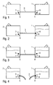
- FIG. 1 shows a tank system according to the invention with a main tank 1 and a sub tank 2, wherein the main tank 1 and the sub tank 2 each have a filler neck and can be filled independently.
- the main tank 1 and the sub tank 2 may be disposed in a truck on opposite sides of the vehicle frame.
- the main tank 1 is connected via a compensation line 3 with the sub tank 2, to allow a level balance between the main tank 1 and the sub tank 2.
- the equalizing line 3 respectively opens into the main tank 1 and into the secondary tank 2, respectively, in order to enable level compensation by the equalizing line 3 even in the case of low filling levels in the main tank 1 and in the secondary tank 2.
- the tank system shown has a valve arrangement with two outlet valves 4, 5, wherein the outlet valve 4 in the main tank 1 controls the outflow of the diesel fuel from the main tank 1 into the equalization line 3.
- the exhaust valve 5 in the sub tank 2 controls the outflow of the diesel fuel from the sub tank 2 into the equalizing pipe.
- the two exhaust valves 4, 5 each have a valve seat, which opens into the equalizing line 3 and a funnel-shaped valve cage 6 and 7, in which a valve ball 8 and 9 is movably caught.
- valve balls 8, 9 have a lower mass density than the diesel fuel, so that the valve balls 8, 9 float in the diesel fuel.
- valve cages 6, 7 are permeable to the diesel fuel and impermeable to the valve balls 8, 9.
- FIG. 2 shows, however, the state of the tank system at a first filling of the main tank 1 with an empty secondary tank. 2
- valve ball 8 of the exhaust valve 4 of the main tank 1 acts on the valve ball 8 of the exhaust valve 4 of the main tank 1, a buoyancy force due to the diesel fuel, whereby the valve ball 8 floats.
- FIG. 3 shows the state of the tank system according to the invention, when both the main tank 1 and the sub tank 2 are filled.
- FIG. 4 shows the state of the tank system according to the invention in case of leakage of the equalization line 3, which is illustrated by a tearing of the compensation line 3.
- both of the main tank 1 and the sub tank 2 a strong outflow on the exhaust valves 4, 5, whereby the valve balls 8, 9 are pressed into the associated valve seat, which then close the exhaust valves 4, 5. This prevents that in case of leakage of the compensation line 3, a large leakage occurs.
- FIGS. 5 and 6 show in a self-explanatory manner a state diagram or a state table to illustrate the operation of the tank system from the Figures 1-4 , Reference is made to avoid repetition of the above description.
Landscapes
- Engineering & Computer Science (AREA)
- Life Sciences & Earth Sciences (AREA)
- Sustainable Development (AREA)
- Sustainable Energy (AREA)
- Chemical & Material Sciences (AREA)
- Combustion & Propulsion (AREA)
- Transportation (AREA)
- Mechanical Engineering (AREA)
- Loading And Unloading Of Fuel Tanks Or Ships (AREA)
- Cooling, Air Intake And Gas Exhaust, And Fuel Tank Arrangements In Propulsion Units (AREA)
Applications Claiming Priority (1)
| Application Number | Priority Date | Filing Date | Title |
|---|---|---|---|
| DE102013021007.0A DE102013021007A1 (de) | 2013-12-13 | 2013-12-13 | Tankanlage für ein Fahrzeug |
Publications (2)
| Publication Number | Publication Date |
|---|---|
| EP2883733A1 true EP2883733A1 (fr) | 2015-06-17 |
| EP2883733B1 EP2883733B1 (fr) | 2016-02-24 |
Family
ID=51263183
Family Applications (1)
| Application Number | Title | Priority Date | Filing Date |
|---|---|---|---|
| EP14002669.1A Active EP2883733B1 (fr) | 2013-12-13 | 2014-07-31 | Installation de réservoir pour un véhicule |
Country Status (2)
| Country | Link |
|---|---|
| EP (1) | EP2883733B1 (fr) |
| DE (1) | DE102013021007A1 (fr) |
Cited By (4)
| Publication number | Priority date | Publication date | Assignee | Title |
|---|---|---|---|---|
| CN114658576A (zh) * | 2022-03-31 | 2022-06-24 | 东风华神汽车有限公司 | 商用车主、副油箱控制方法、装置、设备及可读存储介质 |
| CN114776493A (zh) * | 2022-04-19 | 2022-07-22 | 潍柴动力股份有限公司 | 一种车辆低温加热方法、装置、系统、设备和存储介质 |
| CN116104823A (zh) * | 2023-03-15 | 2023-05-12 | 航天重型工程装备有限公司 | 一种分体式油箱及液压动力系统 |
| CN117021934A (zh) * | 2023-08-17 | 2023-11-10 | 东风商用车有限公司 | 一种商用车主副油箱结构及监测系统 |
Citations (6)
| Publication number | Priority date | Publication date | Assignee | Title |
|---|---|---|---|---|
| GB1459203A (en) * | 1973-12-07 | 1976-12-22 | Sundaravej K | Fuel storage tanks |
| WO1996026388A1 (fr) * | 1995-02-22 | 1996-08-29 | Charles Bradford Helm | Tube d'equalisation de carburant pour vehicules et son procede d'utilisation |
| JP2001012326A (ja) * | 1999-06-29 | 2001-01-16 | Kubota Corp | 作業機用エンジンの燃料供給装置 |
| US6789568B1 (en) * | 2003-06-17 | 2004-09-14 | Case, Llc | Fluid flow control mechansim |
| WO2009080173A1 (fr) * | 2007-12-22 | 2009-07-02 | Agco Sa | Système de réservoir à carburant |
| US20120180778A1 (en) * | 2011-01-13 | 2012-07-19 | Wacker Neuson Production Americas, LLC | Multiple fuel tank system |
-
2013
- 2013-12-13 DE DE102013021007.0A patent/DE102013021007A1/de not_active Withdrawn
-
2014
- 2014-07-31 EP EP14002669.1A patent/EP2883733B1/fr active Active
Patent Citations (6)
| Publication number | Priority date | Publication date | Assignee | Title |
|---|---|---|---|---|
| GB1459203A (en) * | 1973-12-07 | 1976-12-22 | Sundaravej K | Fuel storage tanks |
| WO1996026388A1 (fr) * | 1995-02-22 | 1996-08-29 | Charles Bradford Helm | Tube d'equalisation de carburant pour vehicules et son procede d'utilisation |
| JP2001012326A (ja) * | 1999-06-29 | 2001-01-16 | Kubota Corp | 作業機用エンジンの燃料供給装置 |
| US6789568B1 (en) * | 2003-06-17 | 2004-09-14 | Case, Llc | Fluid flow control mechansim |
| WO2009080173A1 (fr) * | 2007-12-22 | 2009-07-02 | Agco Sa | Système de réservoir à carburant |
| US20120180778A1 (en) * | 2011-01-13 | 2012-07-19 | Wacker Neuson Production Americas, LLC | Multiple fuel tank system |
Cited By (5)
| Publication number | Priority date | Publication date | Assignee | Title |
|---|---|---|---|---|
| CN114658576A (zh) * | 2022-03-31 | 2022-06-24 | 东风华神汽车有限公司 | 商用车主、副油箱控制方法、装置、设备及可读存储介质 |
| CN114776493A (zh) * | 2022-04-19 | 2022-07-22 | 潍柴动力股份有限公司 | 一种车辆低温加热方法、装置、系统、设备和存储介质 |
| CN114776493B (zh) * | 2022-04-19 | 2024-03-19 | 潍柴动力股份有限公司 | 一种车辆低温加热方法、装置、系统、设备和存储介质 |
| CN116104823A (zh) * | 2023-03-15 | 2023-05-12 | 航天重型工程装备有限公司 | 一种分体式油箱及液压动力系统 |
| CN117021934A (zh) * | 2023-08-17 | 2023-11-10 | 东风商用车有限公司 | 一种商用车主副油箱结构及监测系统 |
Also Published As
| Publication number | Publication date |
|---|---|
| EP2883733B1 (fr) | 2016-02-24 |
| DE102013021007A1 (de) | 2015-06-18 |
Similar Documents
| Publication | Publication Date | Title |
|---|---|---|
| DE202010011973U1 (de) | Ölablassvorrichtung | |
| DE3121621C2 (de) | "Entlüftungseinrichtung für Kraftstofftanks von Fahrzeugen, insbesondere von Kraftfahrzeugen" | |
| DE102015218872B3 (de) | Zwangsverriegelung eines Frischwasseranschlusses eines Schienenfahrzeugs | |
| EP2883733B1 (fr) | Installation de réservoir pour un véhicule | |
| DE3030288C2 (de) | Vorrichtung zum Entlüften von Kraftstoffbehältern, insbesondere für Kraftfahrzeuge | |
| DE102010049644A1 (de) | Kraftstoffbehälter für Kfz | |
| EP3368366B1 (fr) | Réservoir de carburant doté d'un clapet d'entrée anti-retour | |
| DE102013013212A1 (de) | Universelles Abschaltventil | |
| EP2842785B1 (fr) | Réservoir de véhicule utilitaire | |
| DE102010001216A1 (de) | Behälter, insbesondere für hydraulische Fahrzeugbremsanlagen | |
| DE102008014820A1 (de) | Kraftstofftank für Kraftfahrzeuge | |
| DE102015222669A1 (de) | Einfüllsystem an einem Kraftfahrzeug | |
| DE102016207741A1 (de) | Tanksystem eines Kraftfahrzeugs mit einem Volumenveränderungselement | |
| DE102005043745A1 (de) | Entlüftungssystem mit Siphonentleerung | |
| DE3342871A1 (de) | Behaelteranlage fuer fluessigkeiten, insbesondere tankanlage fuer kraftfahrzeuge | |
| EP0502326A1 (fr) | Barrière d'écoulement pour système d'aération d'un réservoir de carburant | |
| DE102006055285B4 (de) | Ölfilter mit Bypassventil und Ölbehälter | |
| DE102009007429A1 (de) | Schienenfahrzeug mit Fahrzeugtürdichtung | |
| EP3649352B1 (fr) | Dispositif de compensation sous la forme d'un réservoir | |
| DE102014202361A1 (de) | Kraftstofftanksystem | |
| EP2761982A1 (fr) | Soupape de sécurité pour un réservoir en matière synthétique, notamment une cuve à lisier en matière synthétique | |
| DE10027569B4 (de) | Kraftstofftank eines Kraftfahrzeuges mit Druckentlüftungsventilen | |
| DE102019108893A1 (de) | Tankanlage für ein Kraftfahrzeug | |
| DE1052836B (de) | Druckluftreiniger fuer Druckluftbremsanlagen in Fahrzeugen, insbesondere Kraftfahrzeugen | |
| EP2486255B1 (fr) | Système de refroidissement, notamment pour un moteur à combustion interne |
Legal Events
| Date | Code | Title | Description |
|---|---|---|---|
| PUAI | Public reference made under article 153(3) epc to a published international application that has entered the european phase |
Free format text: ORIGINAL CODE: 0009012 |
|
| 17P | Request for examination filed |
Effective date: 20150317 |
|
| AK | Designated contracting states |
Kind code of ref document: A1 Designated state(s): AL AT BE BG CH CY CZ DE DK EE ES FI FR GB GR HR HU IE IS IT LI LT LU LV MC MK MT NL NO PL PT RO RS SE SI SK SM TR |
|
| AX | Request for extension of the european patent |
Extension state: BA ME |
|
| GRAP | Despatch of communication of intention to grant a patent |
Free format text: ORIGINAL CODE: EPIDOSNIGR1 |
|
| INTG | Intention to grant announced |
Effective date: 20151014 |
|
| GRAS | Grant fee paid |
Free format text: ORIGINAL CODE: EPIDOSNIGR3 |
|
| INTG | Intention to grant announced |
Effective date: 20151119 |
|
| GRAA | (expected) grant |
Free format text: ORIGINAL CODE: 0009210 |
|
| AK | Designated contracting states |
Kind code of ref document: B1 Designated state(s): AL AT BE BG CH CY CZ DE DK EE ES FI FR GB GR HR HU IE IS IT LI LT LU LV MC MK MT NL NO PL PT RO RS SE SI SK SM TR |
|
| REG | Reference to a national code |
Ref country code: GB Ref legal event code: FG4D Free format text: NOT ENGLISH |
|
| REG | Reference to a national code |
Ref country code: CH Ref legal event code: EP |
|
| REG | Reference to a national code |
Ref country code: AT Ref legal event code: REF Ref document number: 776495 Country of ref document: AT Kind code of ref document: T Effective date: 20160315 |
|
| REG | Reference to a national code |
Ref country code: IE Ref legal event code: FG4D Free format text: LANGUAGE OF EP DOCUMENT: GERMAN |
|
| REG | Reference to a national code |
Ref country code: DE Ref legal event code: R096 Ref document number: 502014000375 Country of ref document: DE |
|
| REG | Reference to a national code |
Ref country code: NL Ref legal event code: FP |
|
| REG | Reference to a national code |
Ref country code: SE Ref legal event code: TRGR |
|
| REG | Reference to a national code |
Ref country code: LT Ref legal event code: MG4D |
|
| REG | Reference to a national code |
Ref country code: FR Ref legal event code: PLFP Year of fee payment: 3 |
|
| PG25 | Lapsed in a contracting state [announced via postgrant information from national office to epo] |
Ref country code: ES Free format text: LAPSE BECAUSE OF FAILURE TO SUBMIT A TRANSLATION OF THE DESCRIPTION OR TO PAY THE FEE WITHIN THE PRESCRIBED TIME-LIMIT Effective date: 20160224 Ref country code: NO Free format text: LAPSE BECAUSE OF FAILURE TO SUBMIT A TRANSLATION OF THE DESCRIPTION OR TO PAY THE FEE WITHIN THE PRESCRIBED TIME-LIMIT Effective date: 20160524 Ref country code: FI Free format text: LAPSE BECAUSE OF FAILURE TO SUBMIT A TRANSLATION OF THE DESCRIPTION OR TO PAY THE FEE WITHIN THE PRESCRIBED TIME-LIMIT Effective date: 20160224 Ref country code: GR Free format text: LAPSE BECAUSE OF FAILURE TO SUBMIT A TRANSLATION OF THE DESCRIPTION OR TO PAY THE FEE WITHIN THE PRESCRIBED TIME-LIMIT Effective date: 20160525 Ref country code: HR Free format text: LAPSE BECAUSE OF FAILURE TO SUBMIT A TRANSLATION OF THE DESCRIPTION OR TO PAY THE FEE WITHIN THE PRESCRIBED TIME-LIMIT Effective date: 20160224 |
|
| PG25 | Lapsed in a contracting state [announced via postgrant information from national office to epo] |
Ref country code: RS Free format text: LAPSE BECAUSE OF FAILURE TO SUBMIT A TRANSLATION OF THE DESCRIPTION OR TO PAY THE FEE WITHIN THE PRESCRIBED TIME-LIMIT Effective date: 20160224 Ref country code: PL Free format text: LAPSE BECAUSE OF FAILURE TO SUBMIT A TRANSLATION OF THE DESCRIPTION OR TO PAY THE FEE WITHIN THE PRESCRIBED TIME-LIMIT Effective date: 20160224 Ref country code: LV Free format text: LAPSE BECAUSE OF FAILURE TO SUBMIT A TRANSLATION OF THE DESCRIPTION OR TO PAY THE FEE WITHIN THE PRESCRIBED TIME-LIMIT Effective date: 20160224 Ref country code: PT Free format text: LAPSE BECAUSE OF FAILURE TO SUBMIT A TRANSLATION OF THE DESCRIPTION OR TO PAY THE FEE WITHIN THE PRESCRIBED TIME-LIMIT Effective date: 20160624 Ref country code: LT Free format text: LAPSE BECAUSE OF FAILURE TO SUBMIT A TRANSLATION OF THE DESCRIPTION OR TO PAY THE FEE WITHIN THE PRESCRIBED TIME-LIMIT Effective date: 20160224 |
|
| PG25 | Lapsed in a contracting state [announced via postgrant information from national office to epo] |
Ref country code: DK Free format text: LAPSE BECAUSE OF FAILURE TO SUBMIT A TRANSLATION OF THE DESCRIPTION OR TO PAY THE FEE WITHIN THE PRESCRIBED TIME-LIMIT Effective date: 20160224 Ref country code: EE Free format text: LAPSE BECAUSE OF FAILURE TO SUBMIT A TRANSLATION OF THE DESCRIPTION OR TO PAY THE FEE WITHIN THE PRESCRIBED TIME-LIMIT Effective date: 20160224 |
|
| REG | Reference to a national code |
Ref country code: DE Ref legal event code: R097 Ref document number: 502014000375 Country of ref document: DE |
|
| PG25 | Lapsed in a contracting state [announced via postgrant information from national office to epo] |
Ref country code: RO Free format text: LAPSE BECAUSE OF FAILURE TO SUBMIT A TRANSLATION OF THE DESCRIPTION OR TO PAY THE FEE WITHIN THE PRESCRIBED TIME-LIMIT Effective date: 20160224 Ref country code: CZ Free format text: LAPSE BECAUSE OF FAILURE TO SUBMIT A TRANSLATION OF THE DESCRIPTION OR TO PAY THE FEE WITHIN THE PRESCRIBED TIME-LIMIT Effective date: 20160224 Ref country code: SK Free format text: LAPSE BECAUSE OF FAILURE TO SUBMIT A TRANSLATION OF THE DESCRIPTION OR TO PAY THE FEE WITHIN THE PRESCRIBED TIME-LIMIT Effective date: 20160224 Ref country code: SM Free format text: LAPSE BECAUSE OF FAILURE TO SUBMIT A TRANSLATION OF THE DESCRIPTION OR TO PAY THE FEE WITHIN THE PRESCRIBED TIME-LIMIT Effective date: 20160224 |
|
| PG25 | Lapsed in a contracting state [announced via postgrant information from national office to epo] |
Ref country code: BE Free format text: LAPSE BECAUSE OF NON-PAYMENT OF DUE FEES Effective date: 20160731 |
|
| PLBE | No opposition filed within time limit |
Free format text: ORIGINAL CODE: 0009261 |
|
| STAA | Information on the status of an ep patent application or granted ep patent |
Free format text: STATUS: NO OPPOSITION FILED WITHIN TIME LIMIT |
|
| 26N | No opposition filed |
Effective date: 20161125 |
|
| PG25 | Lapsed in a contracting state [announced via postgrant information from national office to epo] |
Ref country code: SI Free format text: LAPSE BECAUSE OF FAILURE TO SUBMIT A TRANSLATION OF THE DESCRIPTION OR TO PAY THE FEE WITHIN THE PRESCRIBED TIME-LIMIT Effective date: 20160224 Ref country code: BG Free format text: LAPSE BECAUSE OF FAILURE TO SUBMIT A TRANSLATION OF THE DESCRIPTION OR TO PAY THE FEE WITHIN THE PRESCRIBED TIME-LIMIT Effective date: 20160524 |
|
| PG25 | Lapsed in a contracting state [announced via postgrant information from national office to epo] |
Ref country code: MC Free format text: LAPSE BECAUSE OF FAILURE TO SUBMIT A TRANSLATION OF THE DESCRIPTION OR TO PAY THE FEE WITHIN THE PRESCRIBED TIME-LIMIT Effective date: 20160224 |
|
| REG | Reference to a national code |
Ref country code: IE Ref legal event code: MM4A |
|
| REG | Reference to a national code |
Ref country code: FR Ref legal event code: PLFP Year of fee payment: 4 |
|
| PG25 | Lapsed in a contracting state [announced via postgrant information from national office to epo] |
Ref country code: IE Free format text: LAPSE BECAUSE OF NON-PAYMENT OF DUE FEES Effective date: 20160731 |
|
| PG25 | Lapsed in a contracting state [announced via postgrant information from national office to epo] |
Ref country code: LU Free format text: LAPSE BECAUSE OF NON-PAYMENT OF DUE FEES Effective date: 20160731 |
|
| REG | Reference to a national code |
Ref country code: CH Ref legal event code: PL |
|
| PG25 | Lapsed in a contracting state [announced via postgrant information from national office to epo] |
Ref country code: CH Free format text: LAPSE BECAUSE OF NON-PAYMENT OF DUE FEES Effective date: 20170731 Ref country code: LI Free format text: LAPSE BECAUSE OF NON-PAYMENT OF DUE FEES Effective date: 20170731 |
|
| PG25 | Lapsed in a contracting state [announced via postgrant information from national office to epo] |
Ref country code: HU Free format text: LAPSE BECAUSE OF FAILURE TO SUBMIT A TRANSLATION OF THE DESCRIPTION OR TO PAY THE FEE WITHIN THE PRESCRIBED TIME-LIMIT; INVALID AB INITIO Effective date: 20140731 |
|
| PG25 | Lapsed in a contracting state [announced via postgrant information from national office to epo] |
Ref country code: CY Free format text: LAPSE BECAUSE OF FAILURE TO SUBMIT A TRANSLATION OF THE DESCRIPTION OR TO PAY THE FEE WITHIN THE PRESCRIBED TIME-LIMIT Effective date: 20160224 Ref country code: MK Free format text: LAPSE BECAUSE OF FAILURE TO SUBMIT A TRANSLATION OF THE DESCRIPTION OR TO PAY THE FEE WITHIN THE PRESCRIBED TIME-LIMIT Effective date: 20160224 Ref country code: IS Free format text: LAPSE BECAUSE OF FAILURE TO SUBMIT A TRANSLATION OF THE DESCRIPTION OR TO PAY THE FEE WITHIN THE PRESCRIBED TIME-LIMIT Effective date: 20160224 Ref country code: MT Free format text: LAPSE BECAUSE OF FAILURE TO SUBMIT A TRANSLATION OF THE DESCRIPTION OR TO PAY THE FEE WITHIN THE PRESCRIBED TIME-LIMIT Effective date: 20160224 |
|
| REG | Reference to a national code |
Ref country code: FR Ref legal event code: PLFP Year of fee payment: 5 |
|
| PG25 | Lapsed in a contracting state [announced via postgrant information from national office to epo] |
Ref country code: TR Free format text: LAPSE BECAUSE OF FAILURE TO SUBMIT A TRANSLATION OF THE DESCRIPTION OR TO PAY THE FEE WITHIN THE PRESCRIBED TIME-LIMIT Effective date: 20160224 Ref country code: AL Free format text: LAPSE BECAUSE OF FAILURE TO SUBMIT A TRANSLATION OF THE DESCRIPTION OR TO PAY THE FEE WITHIN THE PRESCRIBED TIME-LIMIT Effective date: 20160224 |
|
| GBPC | Gb: european patent ceased through non-payment of renewal fee |
Effective date: 20180731 |
|
| PG25 | Lapsed in a contracting state [announced via postgrant information from national office to epo] |
Ref country code: GB Free format text: LAPSE BECAUSE OF NON-PAYMENT OF DUE FEES Effective date: 20180731 |
|
| REG | Reference to a national code |
Ref country code: DE Ref legal event code: R081 Ref document number: 502014000375 Country of ref document: DE Owner name: MAN TRUCK & BUS SE, DE Free format text: FORMER OWNER: MAN TRUCK & BUS AG, 80995 MUENCHEN, DE |
|
| REG | Reference to a national code |
Ref country code: AT Ref legal event code: MM01 Ref document number: 776495 Country of ref document: AT Kind code of ref document: T Effective date: 20190731 |
|
| PG25 | Lapsed in a contracting state [announced via postgrant information from national office to epo] |
Ref country code: AT Free format text: LAPSE BECAUSE OF NON-PAYMENT OF DUE FEES Effective date: 20190731 |
|
| PGFP | Annual fee paid to national office [announced via postgrant information from national office to epo] |
Ref country code: NL Payment date: 20250724 Year of fee payment: 12 |
|
| PGFP | Annual fee paid to national office [announced via postgrant information from national office to epo] |
Ref country code: DE Payment date: 20250728 Year of fee payment: 12 |
|
| PGFP | Annual fee paid to national office [announced via postgrant information from national office to epo] |
Ref country code: IT Payment date: 20250721 Year of fee payment: 12 |
|
| PGFP | Annual fee paid to national office [announced via postgrant information from national office to epo] |
Ref country code: FR Payment date: 20250725 Year of fee payment: 12 |
|
| PGFP | Annual fee paid to national office [announced via postgrant information from national office to epo] |
Ref country code: SE Payment date: 20250725 Year of fee payment: 12 |