EP2883787A1 - Antriebsmechanismus für eine verformbare Tragflächenvorderkante - Google Patents
Antriebsmechanismus für eine verformbare Tragflächenvorderkante Download PDFInfo
- Publication number
- EP2883787A1 EP2883787A1 EP13196994.1A EP13196994A EP2883787A1 EP 2883787 A1 EP2883787 A1 EP 2883787A1 EP 13196994 A EP13196994 A EP 13196994A EP 2883787 A1 EP2883787 A1 EP 2883787A1
- Authority
- EP
- European Patent Office
- Prior art keywords
- drive mechanism
- skin
- movement
- structural component
- linear movement
- Prior art date
- Legal status (The legal status is an assumption and is not a legal conclusion. Google has not performed a legal analysis and makes no representation as to the accuracy of the status listed.)
- Granted
Links
Images




Classifications
-
- B—PERFORMING OPERATIONS; TRANSPORTING
- B64—AIRCRAFT; AVIATION; COSMONAUTICS
- B64C—AEROPLANES; HELICOPTERS
- B64C3/00—Wings
- B64C3/38—Adjustment of complete wings or parts thereof
- B64C3/44—Varying camber
- B64C3/48—Varying camber by relatively-movable parts of wing structures
-
- F—MECHANICAL ENGINEERING; LIGHTING; HEATING; WEAPONS; BLASTING
- F16—ENGINEERING ELEMENTS AND UNITS; GENERAL MEASURES FOR PRODUCING AND MAINTAINING EFFECTIVE FUNCTIONING OF MACHINES OR INSTALLATIONS; THERMAL INSULATION IN GENERAL
- F16H—GEARING
- F16H21/00—Gearings comprising primarily only links or levers, with or without slides
- F16H21/10—Gearings comprising primarily only links or levers, with or without slides all movement being in, or parallel to, a single plane
- F16H21/44—Gearings comprising primarily only links or levers, with or without slides all movement being in, or parallel to, a single plane for conveying or interconverting oscillating or reciprocating motions
-
- Y—GENERAL TAGGING OF NEW TECHNOLOGICAL DEVELOPMENTS; GENERAL TAGGING OF CROSS-SECTIONAL TECHNOLOGIES SPANNING OVER SEVERAL SECTIONS OF THE IPC; TECHNICAL SUBJECTS COVERED BY FORMER USPC CROSS-REFERENCE ART COLLECTIONS [XRACs] AND DIGESTS
- Y10—TECHNICAL SUBJECTS COVERED BY FORMER USPC
- Y10T—TECHNICAL SUBJECTS COVERED BY FORMER US CLASSIFICATION
- Y10T74/00—Machine element or mechanism
- Y10T74/18—Mechanical movements
- Y10T74/18888—Reciprocating to or from oscillating
- Y10T74/1892—Lever and slide
- Y10T74/18928—Straight line motions
Definitions
- the invention relates to a drive mechanism for driving a deformation of a skin of a deformable structural component of a fluid-dynamic, in particular aerodynamic, flow body, which structural component has a skin to be deformed and a rotatably mounted load introduction device for introducing the deformation force to the skin. Furthermore, the invention relates to a deformable structural component for a fluid-dynamic, in particular aerodynamic, body of a vehicle, in particular an aircraft, comprising a skin to be deformed and such a drive mechanism. The invention further relates to a fluid-dynamic, in particular aerodynamic, flow body of a vehicle provided with such a deformable structural component, such as e.g. a wing or the like of an aircraft. Finally, the invention relates to a buoyancy aid for an aircraft.
- Adaptive structures of the type studied in the SADE project are particularly suitable for the deformation of aerodynamic surfaces of aircraft, such as wings, fins or rotor blades.
- tipping lugs English: Droop Leading Edge Flap or Droop Nose
- Droop Nose designated tipping nose the entire wing nose is angled downwards. This increases the wing curvature.
- a Execution of a tilting nose is realized eg on the Airbus A380 as so-called Droop-Nose Device on the inner wing.
- the SADE project's research aims to achieve adaptive structures for aerodynamic bodies that can provide greater geometric freedom, local curvature and strain reduction, and more laminar flow than known droop-nose devices.
- the invention is thus directed in a preferred embodiment to a drive concept for a deformable structural component with a skin to be deformed over a large area and, which structural component can be deformed by a drive mechanism in order to create an adaptive structure.
- the force is preferably introduced by means of an auxiliary structure (eg Omegastringer) to reduce local voltage peaks and the Deformability of the primary structure does not hinder.
- Fittings are attached to this auxiliary structure in order to enable a movably mounted introduction of force (eg via struts and condyle).
- the struts are in previous solutions each at a main lever, each main lever is provided with a servomotor to rotate the main lever.
- a structure as slim as possible e.g. a slim laminar wing - advantageous.
- the previous solutions can not be used for the given geometry due to lack of space; so that the functionality of the required kinematics would not exist.
- the invention has for its object to provide a drive concept for a kinematics of an adaptive structure with a small footprint for a large deformation under high loads with reduced complexity of the drive.
- the invention provides a drive mechanism for driving a deformation of a skin of a deformable structural component of a fluid-dynamic, in particular aerodynamic, flow body, which structural component has a skin to be deformed and a rotatably mounted load introduction device for introducing the deformation force to the skin, wherein the drive mechanism comprises a linearly movable linearly driven moving unit and a transmission element for converting a linear movement of the linear motion unit in a rotational movement of the load introduction device.
- the transmission element has a transfer lever for converting the linear movement into a rotational movement.
- the transfer lever acts on the linear movement unit and on the load introduction device.
- the transfer lever is designed as a toggle lever or as part of a toggle mechanism.
- the transfer lever is articulated so that it can both move in one plane and move out of the plane.
- the transfer lever is mounted multi-axially articulated on the linear motion unit.
- the transfer lever is mounted multi-axially articulated on the load introduction device.
- the transfer lever is mounted uniaxially articulated on the linear movement unit and the linear movement element is rotatably mounted about an axis of rotation extending essentially in the direction of movement of the linear movement element.
- the linear movement unit is designed and arranged such that the direction of movement of the linear movement unit extends at least with a movement direction component, preferably with its largest movement direction component or altogether parallel to a rotation axis of the rotary movement of the load introduction device.
- the linear motion unit has a drive rod displaceably mounted in its longitudinal direction.
- the linear movement unit has a plurality of rod elements which are successively articulated to each other in the direction of movement.
- the invention relates to a deformable structural component for a fluid dynamic body of a vehicle provided with such a drive mechanism, in particular for an aerodynamic body of an aircraft, comprising a skin to be deformed and the drive mechanism for driving the deformation movement.
- the skin is fixedly secured at its end regions and the drive mechanism is adapted to deform a curved mid-region of the skin between the end regions.
- the invention provides a fluid-dynamic, in particular aerodynamic, flow body provided with such a structural component, which is driven in a driven manner by the drive mechanism, in which an end edge region is formed by the deformable structural component.
- the invention provides a buoyancy aid for an aircraft, formed as a droopnose device with such a structural component that is driven in a driven manner by the drive mechanism.
- the object of a preferred embodiment of the invention is to adaptively deform a leading edge of a laminar profile (such as a wing leading edge of a laminar blade).
- a drive concept or kinematics is required.
- laminar profiles there is a lack of space, which allows only a limited number of actuators.
- the loads to be handled are very high.
- a classic rotationally driven kinematics is not feasible for very slim laminar profiles to be deformed.
- a high load occurs with only a small amount of space available.
- Another goal was to find a solution to reduce complexity.
- a linear connection to the kinematics is proposed as a drive concept in which the linear movement is converted into a rotational movement by targeted positioning of levers.
- a lever is articulated so that it can move both in the plane and out of it.
- the inventive concept greatly reduce the complexity. Further advantages include a possible weight reduction, high stability and greater reliability.
- the drive concept basically allows any number of kinematics stations to be driven simultaneously. This greatly reduces the complexity of the system. Another advantage is that the actuator (s) may be load-free at the minimum and maximum kinematics deflection, thereby increasing the safety of the system.
- the introduction of force preferably takes place by means of an auxiliary structure (for example Omegastringer), in order to reduce local stress peaks and not to hinder the deformability of the primary structure.
- Fittings are preferably attached to this auxiliary structure in order to enable a movably mounted introduction of force (for example via struts and condyle).
- the struts are preferably each located on one of several main levers. With the drive concept according to the invention, however, the main lever can drive much easier and safer than before.
- a linear movement of a linear motion unit can be easily transmitted along a wing edge or any other elongated structure to be deformed and tap in several places, so as to drive several main lever.
- About a transfer lever can be the linear movement elegant and simple and yet safe and implement with high loads and low maintenance in a rotational movement of the respective main lever, whereby the weight is low.
- FIG. 1 and 2 The following is based on the representations of Fig. 1 and 2 an embodiment of an adaptive thin-walled structure 10 with a deformable structural component 12 using the example of a fluid dynamic flow body - here in the form of an aerodynamic flow body 14 with deformable aerodynamic surface - explained in more detail.
- the invention is generally applicable to all thin-walled adaptive structure with deformable structural components, which have a skin 16 to be deformed and a (eg indirect) load introduction, for example via stiffening profiles 18, for deforming the skin 16, applicable.
- a drive mechanism 11 for the adaptive structure 10 will be explained in more detail below. Subsequently, an embodiment of the drive mechanism 11 based on the representation of Fig. 3 to 7 explained in more detail.
- Fig. 1 an aircraft 20, here shown for example in the form of an aircraft 22, wherein the wings 24 are provided with droop-nose buoyancy aids 26, which are realized by the adaptive structure 10.
- Fig. 2 is a cross-sectional view taken along the line II-II of Fig. 1 shown.
- the adaptive structure 10 accordingly has the deformable structural component 12.
- the deformable structural component 12 is formed as part of the aerodynamic flow body 14 and has the skin 16 which is to be deformed over a large area for adaptation of the aerodynamic flow body 14 to a desired aerodynamic effect.
- the adaptive structure 10 has a primary structure 28 to be deformed, which is to be deformed as undisturbed as possible, with no gaps and no excessive radii of curvature at the top.
- the deformation force is introduced via an auxiliary structure 30 only indirectly into the primary structure 28.
- the auxiliary structure 30 has a plurality of stiffening profiles 18.
- the stiffening profiles 18 are formed by Omegastringer 32.
- Other stiffening profile shapes are possible;
- hollow profiles are preferred with a distributed over a larger area attachment to the skin 16th
- stiffening profiles 18 are mounted on an inner surface 34 of the skin 16 to be deformed.
- the drive mechanism 11 has at least one actuator 36 for generating a desired deformation force.
- the drive mechanism 11 is connected to the stiffening profiles 18 via a load introduction device 38 for introducing the deformation load.
- the load introduction device 38 has load introduction elements 40, which initiate the load at points of application 42 - also called attack points - into the stiffening profiles 18 or, more generally, the auxiliary structure 30.
- the actuator 36 is designed to generate a linear movement.
- the actuator 36 has a servomotor 44, which drives a linear movement on the drive mechanism 11 via a motor-driven spindle (not shown).
- a hydraulically or pneumatically or magnetically or otherwise trained piston mechanism is provided as the actuator 36.
- linear motors or a servomotor with a rack, etc. are conceivable.
- the drive mechanism 11 drives a rotary motion on the load introduction device 38, initiates the force via struts 48 with condyle 50 in trained as fittings 52 load introduction elements 40 at the application point 42.
- the drive mechanism 11 is configured to drive the deformation of the skin 16 of the deformable structural member 12 of the aerodynamic flow body 14.
- the structural member 12 has the skin 16 to be deformed and the rotatably mounted load introduction device 38 for initiating the deformation force on the skin 16 on.
- the drive mechanism 11 further comprises a linear movement unit 60 driven linearly by the actuator 36 and a transmission element 62 for converting a linear movement of the linear motion unit 60 into a rotational movement of the load introduction device 38.
- the transmission element 62 is in particular formed by a transfer lever 64, which is articulated on the one hand to the linear movement unit 60 and on the other hand to the load introduction device 38.
- the Lasteinleit Taiwan 38 has a main lever 54 which is formed with two arms, which is articulated on a first arm 66 acting as a transmission element 62 for converting the linear movement in a rotary transfer lever 64 and on a second arm 68, the struts 48 with the rod ends 50th attack.
- the first arm 66 and the transfer lever 64 form a toggle mechanism with which even high loads are transferable.
- the stiffening profiles 18 are each formed by a Omegastringer 32, which extends in the longitudinal direction of the structural component 12 to be deformed.
- Illustrated exemplary use of the adaptive structure 10 corresponds to the longitudinal direction of the spanwise direction.
- fittings 52 At several spaced locations are on of fittings 52, of which in the figures only one is shown.
- the linear movement direction 68 of the linear motion unit 60 also extends parallel to this longitudinal direction and with at least one directional component parallel to the axis of rotation of the rotary movement of the load introduction device, ie in particular the single main lever 54th
- the Li-nearschisplatz is substantially parallel to the direction of the wing edge, so directed substantially in the spanwise direction.
- the main lever 54 is directed substantially in the direction of flight, wherein its axis of rotation extends substantially parallel to the linear movement direction 58
- the load introduction device 38 as a load introduction element 40, the main lever 54 and hinged thereto at the free end struts 48 with condyle 50 for connecting to the fitting 52 on the omega strippers 32.
- the skin 16 is fixed in position at end regions or transition regions 70, where the deformable structure 10 merges into a solid structure of the aerodynamic flow body 14.
- the skin 16 is attached to these transition regions 70 on a wall 72 of the wing structure. From the lower transition region to the upper transition region, the skin is arcuately curved to form the wing leading edge 74. The entire curved area of the skin 16 can be deformed overall.
- the load introduction device 38 further has a fastening fitting 76, which is also stationary, e.g. attached to the wall 72 of the wing structure. At this mounting bracket 76, the axis of rotation 78 of the rotary rotational movement of the load introduction device 38 is defined.
- the linear motion unit 60 of the drive mechanism 11 includes a drive rod 82 having an actuator port 84 for coupling to an output member of the actuator 86 at one end.
- the drive rod 82 is mounted in guide rails 86, which may be arranged on the mounting bracket 76, linearly displaceable in the linear movement direction 58.
- the drive rod 82 is preferably divided into a plurality of rod elements 87, 88, which are coupled by means of a coupling joint 89 hinged together to compensate for a bending of the aerodynamic flow body 14, in particular a bending of the wing 24.
- the drive rod 82 can be guided to a plurality of main levers 54 and thus drive a plurality of main levers 54 together.
- the drive rod 82 has a hinge connection 90 for the articulated, ie, for example, rotatable, articulation of a first end of the transfer lever 64.
- the joint formed by the hinge connection 90 between the transfer lever 64 and the drive rod 82 is a multi-axis joint, on the one hand to allow a rotation of the transfer lever 64 in a direction aligned in the direction of linear movement 58 and in the vertical direction and also a forward pivoting of the transfer lever 64 forward, ie, to allow for the skin to be deformed, so as to compensate for the movement of the first arm 66 of the main lever 54.
- the joint connection 90 may be, for example, a part of a universal joint or a ball joint. With a corresponding joint with several degrees of freedom the second end of the transfer lever 64 is articulated to the first arm 66.
- the joint on the joint connection 90 is a pure hinge joint with only one degree of freedom, and the drive rod 82 is rotatably mounted about its longitudinal axis.
Landscapes
- Engineering & Computer Science (AREA)
- Mechanical Engineering (AREA)
- General Engineering & Computer Science (AREA)
- Aviation & Aerospace Engineering (AREA)
- Transmission Devices (AREA)
- Automation & Control Theory (AREA)
- Actuator (AREA)
Abstract
Description
- Die Erfindung betrifft einen Antriebsmechanismus zum Antreiben einer Verformung einer Haut eines verformbaren Strukturbauteils eines fluiddynamischen, insbesondere aerodynamischen, Strömungskörpers, welches Strukturbauteil eine zu verformende Haut und eine drehbeweglich gelagerte Lasteinleitungseinrichtung zur Einleitung der Verformungskraft auf die Haut aufweist. Weiter betrifft die Erfindung ein verformbares Strukturbauteil für einen fluiddynamischen, insbesondere aerodynamischen, Körper eines Fahrzeugs, insbesondere Luftfahrzeugs, umfassend eine zu verformende Haut und einen derartigen Antriebsmechanismus. Weiter betrifft die Erfindung einen mit einem derartigen verformbaren Strukturbauteil versehenen fluiddynamischen, insbesondere aerodynamischen, Strömungskörper eines Fahrzeugs, wie z.B. einen Flügel oder dgl. eines Luftfahrzeugs. Schließlich betrifft die Erfindung eine Auftriebshilfe für ein Flugzeug.
- Ein verformbares Strukturbauteil mit Antriebsmechanismus zum Antreiben der Verformung ist beispielsweise in dem Forschungsprojekt "SmartLED" (LuFo4) sowie in dem Forschungsprojekt "SADE(EU)" entwickelt und untersucht worden. Nähere Einzelheiten zu dem Projekt "SADE" sowie einen Nachweis für Veröffentlichungen hierzu sind unter der Webseite www.sade-projekt.eu/index.html abrufbar.
- Adaptive Strukturen der in dem Projekt SADE untersuchten Art sind besonders geeignet zur Verformung von aerodynamischen Flächen von Luftfahrzeugen, wie z.B. Flügeln, Flossen oder Rotorblättern. Insbesondere bei Flugzeugflügeln ist es vorteilhaft, als Auftriebshilfe anstatt konventionellen Vorflügeln sogenannte Kippnasen (Englisch: Droop Leading Edge Flap oder Droop Nose) zu verwenden. Bei der im Folgenden "Droop Nose" bezeichneten Kippnase wird die komplette Flügelnase nach unten abgewinkelt. Dadurch erhöht sich die Flügelwölbung. Eine Ausführung einer Kippnase ist z.B. beim Airbus A380 als sogenannte Droop-Nose Device am Innenflügel realisiert.
- Konventionelle Vorflügel sind ungeeignet für laminare Umströmung und darüber hinaus eine dominierende Lärmquelle. Beim Airbus A380 ist dagegen eine Droop-Nose Device durch eine Starrkörperbewegung realisiert, was bereits größere Vorteile gegenüber konventionellen Vorflügeln bedingt.
- Die Untersuchungen des SADE-Projekts zielen darauf ab, adaptive Strukturen für aerodynamische Körper zu erreichen, mit denen gegenüber bekannten Droop-Nose-Vorrichtungen größere geometrische Freiheiten, eine Verringerung von lokalen Krümmungen und Belastungen und mehr laminare Umströmungen erreichbar sind.
- Bei früheren Kippnase-Lösungen wird die gesamte Vordernase des Flügels insgesamt als Starrkörper bewegt. Bei dem SADE-Projekt geht man jedoch von dem Ansatz aus, die Primärstruktur zu verformen. Insoweit kann man ohne Spalte mit einer geschlossenen aerodynamischen Fläche arbeiten, große lokale Krümmungsradien vermeiden und aufgrund dessen auch eine verbesserte cp-Verteilung und eine geringere Ablösungstendenz erreichen.
- Die Erfindung ist somit in bevorzugter Ausgestaltung auf ein Antriebskonzept für ein verformbares Strukturbauteil mit einer großflächig zu verformenden Haut und gerichtet, welches Strukturbauteil durch einen Antriebsmechanismus verformbar ist, um eine adaptive Struktur zu schaffen.
- Bei bisherigen verformbaren, adaptiven, dünnwandigen Strukturen, wie z.B. für eine Droop Nose, erfolgt die Krafteinleitung bevorzugt mittels einer Hilfsstruktur (z.B. Omegastringer), um lokale Spannungsüberhöhungen zu reduzieren und die Verformbarkeit der Primärstruktur nicht zu behindern. An dieser Hilfsstruktur werden Beschläge angebracht, um hierüber eine beweglich gelagerte Krafteinleitung (z.B. via Streben und Gelenkkopf) zu ermöglichen. Die Streben sitzen bei bisherigen Lösungen jeweils an einem Haupthebel, wobei jeder Haupthebel mit einem Stellmotor versehen ist, um den Haupthebel zu drehen.
- Will man jedoch einen Flügel oder einen sonstigen fluiddynamischen Körper für ein Fahrzeug, wie insbesondere einen aerodynamischen Körper für ein Luftfahrzeug, schaffen, der laminar umströmt werden kann, dann wäre eine möglichst schlanke Struktur - z.B. ein schlanker Laminar-Flügel - vorteilhaft. Bei besonders schlanken Laminar-Flügeln sind die bisherigen Lösungen bei der gegebenen Geometrie aus Platzmangel nicht verwendbar; damit wäre die Funktionalität der benötigten Kinematik nicht gegeben.
- Der Erfindung liegt die Aufgabe zugrunde, ein Antriebskonzept für eine Kinematik einer adaptiven Struktur mit geringem Platzbedarf für eine große Deformation unter großen Lasten bei verringerter Komplexität des Antriebes zu schaffen.
- Diese Aufgabe wird durch ein Antriebsmechanismus nach Anspruch 1 gelöst. Vorteilhafte Verwendungen des Antriebsmechanismus sind Gegenstand der Nebenansprüche.
- Vorteilhafte Ausgestaltungen der Erfindung sind Gegenstand der Unteransprüche.
- Gemäß einem Aspekt schafft die Erfindung einen Antriebsmechanismus zum Antreiben einer Verformung einer Haut eines verformbaren Strukturbauteils eines fluiddynamischen, insbesondere aerodynamischen, Strömungskörpers, welches Strukturbauteil eine zu verformende Haut und eine drehbeweglich gelagerte Lasteinleitungseinrichtung zur Einleitung der Verformungskraft auf die Haut aufweist, wobei der Antriebsmechanismus eine linear beweglich angetriebene Linearbewegungseinheit und ein Getriebeelement zum Umsetzen einer Linearbewegung der Linearbewegungseinheit in eine Drehbewegung der Lasteinleiteinrichtung umfasst.
- Es ist bevorzugt, dass das Getriebelement einen Umsetzhebel zum Umsetzen der Linearbewegung in eine rotatorische Bewegung aufweist.
- Es ist bevorzugt, dass der Umsetzhebel an der Linearbewegungseinheit und an der Lasteinleiteinrichtung angreift.
- Es ist bevorzugt, dass der Umsetzhebel als Kniehebel oder als Teil eines Kniehebelmechanismus ausgebildet ist.
- Es ist bevorzugt, dass der Umsetzhebel gelenkig so gelagert ist, dass er sich sowohl in einer Ebene bewegen kann als auch sich aus der Ebene heraus bewegen kannn.
- Es ist bevorzugt, dass der Umsetzhebel an der Linearbewegungseinheit mehrachsig gelenkig gelagert ist.
- Es ist bevorzugt, dass der Umsetzhebel an der Lasteinleitungseinrichtung mehrachsig gelenkig gelagert ist.
- Es ist bevorzugt, dass der Umsetzhebel an der Linearbewegungseinheit einachsig gelenkig gelagert ist und das Linearbewegungselement um eine im Wesentlichen in Bewegungsrichtung des Linearbewegungselement verlaufende Verdrehachse drehbar gelagert ist.
- Es ist bevorzugt, dass die Linearbewegungseinheit derart ausgebildet und angeordnet ist, dass die Bewegungsrichtung der Linearbewegungseinheit zumindest mit einer Bewegungsrichtungskomponente, vorzugsweise mit ihrer größten Bewegungsrichtungskomponente oder insgesamt parallel zu einer Drehachse der Drehbewegung der Lasteinleiteinrichtung verläuft.
- Es ist bevorzugt, dass die Linearbewegungseinheit eine in ihrer Längsrichtung verschiebbar gelagerte Antriebsstange aufweist.
- Es ist bevorzugt, dass die Linearbewegungseinheit mehrere in Bewegungsrichtung aufeinanderfolgende gelenkig aneinander gekoppelte Stangenelemente aufweist.
- Gemäß einem weiteren Aspekt betrifft die Erfindung ein mit einem derartigen Antriebsmechanismus versehenes verformbares Strukturbauteil für einen fluiddynamischen Körper eines Fahrzeugs - insbesondere für einen aerodynamischen Körper eines Luftfahrzeugs -, umfassend eine zu verformende Haut als und den Antriebsmechanismus zum Antreiben der Verformbewegung.
- Es ist bevorzugt, dass die Haut an ihren Endbereichen ortsfest befestigt ist und der Antriebsmechanismus dazu ausgebildet ist, einen zwischen den Endbereichen gekrümmt verlaufenden Mittelbereich der Haut zu verformen.
- Gemäß einem weiteren Aspekt schafft die Erfindung einen mit einem derartigen, mit dem Antriebsmechanismus angetrieben verformbaren Strukturbauteil versehenen fluiddynamischen, insbesondere aerodynamischen, Strömungskörper, bei dem ein Endkantenbereich durch das verformbare Strukturbauteil gebildet ist. Gemäß einem weiteren Aspekt schafft die Erfindung eine mit einem derartigen, mit dem Antriebsmechanismus angetrieben verformbaren Strukturbauteil gebildete, als Droopnose-Vorrichtung ausgebildete Auftriebshilfe für ein Flugzeug.
- Ziel einer bevorzugten Ausgestaltung der Erfindung ist es, eine Vorderkante eines Laminarprofils (wie z.B. eine Flügelvorderkante eines Laminar-Flügels) adaptiv verformbar zu gestalten. Hierzu wird ein Antriebskonzept bzw. eine Kinematik benötigt. Gerade bei Laminarprofilen gibt es aber einen mangelnden Bauraum, der nur eine begrenzte Anzahl von Aktuatoren zulässt. Zusätzlich sind die zu bewältigenden Lasten sehr hoch. Eine klassische rotatorisch angetriebene Kinematik ist bei sehr schlanken zu verformenden Laminarprofilen nicht machbar. Insbesondere tritt bei der bevorzugten Verwendbarkeit als Droop-Nose-Auftriebshilfe an Vorderkanten von Flügeln von Luftfahrzeugen eine hohe Last bei nur geringem zur Verfügung stehenden Bauraum auf.
- Ein weiteres Ziel war, eine Lösung zur Reduktion der Komplexität zu finden.
- Bisherige, bei dem SADE-Projekt untersuchte rotatorische Kinematiken sind bei sehr schlanken Laminarprofilen mit geringem Bauraum nicht anwendbar, wenngleich sie auch in ihrem Verwendungszweck eine ähnliche Lösung - Verformung einer Flügelvorderkante - bieten. Die bisher ins Auge gefasste Lösung ist deutlich komplexer und geometrisch weniger flexibel als das hier vorgestellte Antriebskonzept.
- Gemäß einer besonders bevorzugten Ausgestaltung der Erfindung wird als Antriebskonzept eine lineare Anbindung an die Kinematik vorgeschlagen, bei dem durch gezielte Positionierung von Hebeln die Linearbewegung in eine rotatorische Bewegung umgesetzt wird. Dazu wird ein Hebel so gelenkig gelagert, dass er sich sowohl in der Ebene als auch aus ihr heraus bewegen kann.
- Generell lässt sich durch das erfindungsgemäße Konzept Bauraum gewinnen und die Komplexität stark reduzieren. Weitere Vorteile sind eine mögliche Gewichtsreduktion, eine hohe Stabilität und eine größere Ausfallsicherheit. Zusätzlich lassen sich durch das Antriebskonzept grundsätzlich beliebig viele Kinematikstationen gleichzeitig antreiben. Dadurch wird die Komplexität des Systems stark reduziert. Ein weiterer Vorteil ist, dass der oder die Aktuatoren beim minimalen und maximalen Kinematikausschlag lastfrei sein können, wodurch die Sicherheit des Systems erhöht wird.
- Wie bei bisherigen verformbaren, adaptiven, dünnwandigen Strukturen, wie z.B. für eine Droop Nose, erfolgt auch bei bevorzugten Anwendungen der Erfindung die Krafteinleitung bevorzugt mittels einer Hilfsstruktur (z.B. Omegastringer), um lokale Spannungsüberhöhungen zu reduzieren und die Verformbarkeit der Primärstruktur nicht zu behindern. Bevorzugt werden an dieser Hilfsstruktur Beschläge angebracht, um hierüber eine beweglich gelagerte Krafteinleitung (z.B. via Streben und Gelenkkopf) zu ermöglichen. Die Streben sitzen vorzugsweise jeweils an einem von mehreren Haupthebeln. Mit dem erfindungsgemäßen Antriebskonzept lassen sich die Haupthebel jedoch viel einfacher und sicherer als bisher antreiben. Eine Linearbewegung einer Linearbewegungseinheit lässt sich leicht entlang einer Flügelkante oder einer sonstigen länglichen zu verformenden Struktur übertragen und an mehreren Stellen abgreifen, um so auch mehrere Haupthebel anzutreiben. Über einen Umsetzhebel lässt sich die Linearbewegung elegant und einfach und dennoch sicher und auch mit hohen Lasten und auch wartungsarm in eine Drehbewegung des jeweiligen Haupthebels umsetzen, wobei auch der Gewichtsaufwand gering ist.
- Im Folgenden werden Ausführungsbeispiele der Erfindung anhand der beigefügten Zeichnungen näher erläutert. Dabei zeigen:
- Fig. 1
- eine schematische Draufsicht auf ein Luftfahrzeug in Form eines Flugzeuges mit einer Droop Nose-Auftriebshilfe zum Darstellen eines Beispiels für adaptive Strukturen mit einem verformbaren Strukturbauteil und einem Antriebsmechanismus zum Antreiben einer Verformung;
- Fig. 2
- einen Schnitt entlang der Linie II-II von
Fig. 1 durch die adaptive Struktur und das verformbare Strukturbauteil; - Fig. 3
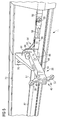
- eine perspektivische Ansicht einer Ausführungsform des Antriebsmechanimus in einer neutralen Position;
- Fig. 4
- eine Ansicht wie in
Fig. 3 des Antriebsmechanismus in einer Position für eine maximale Verformung; - Fig. 5
- eine weitere Ansicht des Antriebsmechanismus, wobei ein Befestigungsbeschlag für eine Lasteinleiteinrichtung zur besseren Darstellung weggelassen worden ist;
- Fig. 6
- eine Darstellung vergleichbar der
Fig. 5 mit beiden Befestigungsbeschlägen; und - Fig. 7
- eine weitere perspektivische Ansicht des Antriebsmechanismus.
- Im Folgenden wird anhand der Darstellungen der
Fig. 1 und 2 ein Ausführungsbeispiel einer adaptiven dünnwandigen Struktur 10 mit einem verformbaren Strukturbauteil 12 am Beispiel eines fluiddynamischen Strömungskörpers - hier z.B. in Form eines aerodynamischen Strömungskörpers 14 mit verformbarer aerodynamischer Fläche - näher erläutert. Die Erfindung ist jedoch allgemein auf alle dünnwandigen adaptiven Struktur mit verformbaren Strukturbauteilen, die eine zu verformende Haut 16 und eine (z.B. indirekte) Lasteinleitung, z.B. über Versteifungsprofile 18, zum Verformen der Haut 16 aufweisen, anwendbar. Insbesondere wird im Folgenden ein Antriebsmechanismus 11 für die adaptive Struktur 10 näher erläutert. Anschließend wird ein Ausführungsbeispiel des Antriebsmechanismus 11 anhand der Darstellung derFig. 3 bis 7 näher erläutert. - Als Beispiel für den fluiddynamischen und insbesondere aerodynamischen Strömungskörper 14 ist in
Fig. 1 ein Luftfahrzeug 20, hier z.B. in Form eines Flugzeuges 22, gezeigt, wobei die Flügel 24 mit Droop-Nose-Auftriebshilfen 26 versehen sind, die durch die adaptive Struktur 10 realisiert werden. - In
Fig. 2 ist eine Querschnittsdarstellung entlang der Linie II-II vonFig. 1 dargestellt. Die adaptive Struktur 10 weist demnach das verformbare Strukturbauteil 12 auf. Das verformbare Strukturbauteil 12 ist als Teil des aerodynamischen Strömungskörpers 14 ausgebildet und weist die Haut 16 auf, die zur Anpassung des aerodynamischen Strömungskörpers 14 an eine gewünschte aerodynamische Wirkung insgesamt großflächig zu verformen ist. - Demnach weist die adaptive Struktur 10 eine zu verformende Primärstruktur 28 auf, die möglichst ungestört verformt werden soll, wobei keine Spalte und keine überhöhten Krümmungsradien an der Oberseite entstehen sollen. Hierzu wird die Verformungskraft über eine Hilfsstruktur 30 nur mittelbar in die Primärstruktur 28 eingeleitet.
- Die Hilfsstruktur 30 weist mehrere Versteifungsprofile 18 auf. Zum Beispiel sind die Versteifungsprofile 18 durch Omegastringer 32 gebildet. Auch andere Versteifungsprofilformen sind möglich; bevorzugt sind jedoch Hohlprofile mit einer auf einer größeren Fläche verteilten Befestigung zu der Haut 16.
- Demnach sind die Versteifungsprofile 18 auf einer inneren Oberfläche 34 der zu verformenden Haut 16 befestigt.
- Der Antriebsmechanismus 11 weist wenigstens einen Aktuator 36 zur Erzeugung einer gewünschten Verformungskraft auf. Der Antriebsmechanismus 11 ist über eine Lasteinleitungseinrichtung 38 zum Einleiten der Verformungslast mit den Versteifungsprofilen 18 verbunden.
- Die Lasteinleitungseinrichtung 38 weist Lasteinleitungselemente 40 auf, die die Last an Angriffspunkten 42 - auch Angriffsstellen genannt - in die Versteifungsprofile 18 oder allgemeiner die Hilfsstruktur 30 einleiten.
- Wie in
Fig. 1 dargestellt ist der Aktuator 36 zum Erzeugen einer Linearbewegung ausgebildet. Z.B. weist der Aktuator 36 einen Stellmotor 44 auf, der über eine motorisch angetrieben Spindel (nicht dargestellt) eine Linearbewegung an dem Antriebsmechanismus 11 antreibt. In anderen Ausgestaltungen ist ein hydraulisch oder pneumatisch oder magnetisch oder sonst wie ausgebildeter Kolbenmechanismus als Aktuator 36 vorgesehen. Auch Linearmotoren oder ein Stellmotor mit einer Zahnstange usw. sind denkbar. - Der Antriebsmechanismus 11 treibt eine Drehbewegung an der Lasteinleitungseinrichtung 38 an, über die Kraft über Streben 48 mit Gelenkkopf 50 in als Beschläge 52 ausgebildete Lasteinleitungselemente 40 am Angriffspunkt 42 einleitet.
- Der Antriebsmechanismus 11 ist zum Antreiben der Verformung der Haut 16 des verformbaren Strukturbauteils 12 des aerodynamischen Strömungskörpers 14 ausgebildet. Das Strukturbauteil 12 weist die zu verformende Haut 16 und die drehbeweglich gelagerte Lasteinleitungseinrichtung 38 zur Einleitung der Verformungskraft auf die Haut 16 auf.
- Wie aus den
Fig. 2 ersichtlich weist der Antriebsmechanismuss 11 weiter eine durch den Aktuator 36 linear beweglich angetriebene Linearbewegungseinheit 60 und ein Getriebeelement 62 zum Umsetzen einer Linearbewegung der Linearbewegungseinheit 60 in eine Drehbewegung der Lasteinleiteinrichtung 38 auf. Das Getriebeelement 62 ist insbesondere durch einen Umsetzhebel 64 gebildet, der einerseits an der Linearbewegungseinheit 60 und andererseits an der Lasteinleiteinrichtung 38 angelenkt ist. - Hierzu weist die Lasteinleiteinrichtung 38 einen Haupthebel 54 auf, der zweiarmig ausgebildet ist, wobei an einem ersten Arm 66 der als Getriebeelement 62 zum Umsetzen der Linearbewegung in eine Drehbewegung wirkende Umsetzhebel 64 angelenkt ist und an einem zweiten Arm 68 die Streben 48 mit den Gelenkköpfen 50 angreifen.
- Der erste Arm 66 und der Umsetzhebel 64 bilden einen Kniehebelmechanismus, mit dem auch hohe Lasten übertragbar sind.
- Die Versteifungsprofile 18 werden jeweils durch einen Omegastringer 32, gebildet, der sich in Längsrichtung des zu verformenden Strukturbauteils 12 erstreckt. Bei der in
Fig. 1 dargestellten beispielhaften Verwendung der adaptiven Struktur 10 entspricht die Längsrichtung der Spannweitenrichtung. An mehreren beabstandeten Stellen sind an von Beschlägen 52 auf, von denen in den Figuren jeweils nur eine dargestellt ist. - Die Linearbewegungsrichtung 68 der Linearbewegungseinheit 60 verläuft parallel zu dieser Längsrichtung und mit wenigstens einer Richtungskompenente auch parallel zu der Drehachse der Drehbewegung der Lasteinleiteinrichtung, d.h. insbesondere der einzelnen Haupthebel 54.
- Bei der gezeigten Ausführungsform einer zu verformenden Flügelkante ist die Li-nearbewegungsrichtung im Wesentlichen parallel zur Richtung der Flügelkante, also im Wesentlichen in Spannweitenrichtung gerichtet. Der Haupthebel 54 ist im Wesentlichen in Flugrichtung gerichtet, wobei seine Drehachse im Wesentlichen parallel zur Linearbewegungsrichtung 58 verläuft
- Wie in
Fig. 2 dargestellt, weist die Lasteinleitungseinrichtung 38 als Lasteinleitungselement 40 den Haupthebel 54 sowie daran am freien Ende angelenkte Streben 48 mit Gelenkkopf 50 zum Verbinden mit dem Beschlag 52 an den Omegastringern 32 auf. - Die Haut 16 ist an Endbereichen oder Übergangsbereichen 70, wo die verformbare Struktur 10 in eine feste Struktur des aerodynamischen Strömungskörpers 14 übergeht, ortsfest fixiert. Zum Beispiel ist die Haut 16 an diesen Übergangsbereichen 70 an einer Wandung 72 der Flügelstruktur befestigt. Von dem unteren Übergangsbereich zu dem oberen Übergangsbereich ist die Haut bogenförmig gekrümmt, um die Flügelvorderkante 74 zu bilden. Der gesamte gekrümmte Bereich der Haut 16 lässt sich insgesamt verformen.
- Die Lasteinleitungseinrichtung 38 weist weiter einen Befestigungsbeschlag 76 auf, der ebenfalls ortsfest, z.B. an der Wandung 72 der Flügelstruktur, befestigt ist. An diesem Befestigungsbeschlag 76 ist die Drehachse 78 der rotatorischen Drehbewegung der Lasteinleitungseinrichtung 38 definiert.
- Im Folgenden wird ein Ausführungsbeispiel des Antriebsmechanismus anhand der Darstellungen in den
Fig. 3 bis 7 näher erläutert. - Die Linearbewegungseinheit 60 des Antriebsmechanismus 11 weist eine Antriebsstange 82 auf, die an einem Ende einen Aktuatoranschluss 84 zum Koppeln an ein Abtriebsglied des Aktuators 86 aufweist.
- Die Antriebsstange 82 ist in Führungsschienen 86, die an dem Befestigungsbeschlag 76 angeordnet sein können, in Linearbewegungsrichtung 58 linear verschiebbar gelagert.
- Die Antriebsstange 82 ist vorzugsweise in mehrere Stangenelemente 87, 88 aufgeteilt, die mittels eines Koppelgelenks 89 gelenkig aneinander gekoppelt sind, um eine Verbiegung des aerodynamischen Strömungskörpers 14, insbesondere eine Verbiegung des Flügels 24 auszugleichen.
- Wie am besten aus
Fig. 7 ersichtlich, kann so die Antriebsstange 82 zu mehreren Haupthebeln 54 geführt werden und somit mehrere Haupthebel 54 gemeinsam antreiben. - Im Bereich der Befestigungsbeschläge 76 eines jeden Haupthebels weist die Antriebsstange 82 einen Gelenkanschluss 90 zum gelenkigen, d.h. z.B. drehbaren, Anlenken eines ersten Endes des Umsetzhebels 64 auf. In einer Ausführungsform ist das durch den Gelenkanschluss 90 gebildete Gelenk zwischen Umsetzhebel 64 und Antriebsstange 82 ein Mehrachsengelenk, um einerseits eine Verdrehung des Umsetzhebels 64 in einer in Linearbewegungsrichtung 58 und in vertikaler Richtung ausgerichteten Ebene zu ermöglichen und außerdem ein Vorschwenken des Umsetzhebels 64 nach vorne, d.h. zu der zu verformenden Haut hin zu ermöglichen, um so die Bewegung des ersten Armes 66 des Haupthebels 54 auszugleichen. Hierzu kann der Gelenkanschluss 90 z.B. ein Teil eines Kreuzgelenks oder eines Kugelgelenks sein. Mit einem entsprechenden Gelenk mit mehreren Freiheitsgraden ist das zweite Ende des Umsetzhebels 64 an dem ersten Arm 66 angelenkt.
- In einer weiteren, hier nicht näher dargestellten Ausführungsform ist das Gelenk am Gelenkanschluss 90 ein reines Scharniergelenk mit nur einem Freiheitsgrad, und die Antriebsstange 82 ist um ihre Längsachse drehbar gelagert.
-
- 10
- adaptive Struktur
- 11
- Antriebsmechanismus
- 12
- verformbares Strukturbauteil
- 14
- aerodynamischer Strömungskörper (Beispiel für einen fluiddynamischen Strömungskörper)
- 16
- zu verformende Haut
- 18
- Versteifungsprofil
- 20
- Luftfahrzeug
- 22
- Flugzeug
- 24
- Flügel
- 26
- Droopnose-Auftriebshilfe
- 28
- zu verformende Primärstruktur
- 30
- Hilfsstruktur
- 32
- Omegastringer
- 34
- Oberfläche
- 36
- Aktuator
- 38
- Lasteinleitungseinrichtung
- 40
- Lasteinleitungselement
- 42
- Angriffspunkt
- 44
- Stellmotor
- 48
- Streben
- 50
- Gelenkkopf
- 52
- Beschlag
- 54
- Haupthebel
- 58
- Linearbewegungsrichtung (Richtung der Linearbewegung)
- 60
- Linearbewegungseinheit
- 62
- Getriebeelement
- 64
- Umsetzhebel
- 66
- erster Arm
- 68
- zweiter Arm
- 70
- Übergangsbereich
- 72
- Wandung
- 74
- Flügelvorderkante
- 76
- Befestigungsbeschlag
- 78
- Drehachse
- 80
- rotatorische Drehbewegung
- 82
- Antriebsstange
- 84
- Aktuatoranschluss
- 86
- Führungsschiene
- 87
- Stangenelement
- 88
- Stangenelement
- 89
- Koppelgelenk
- 90
- Gelenkanschluss
Claims (12)
gekennzeichnet durch eine linear beweglich angetriebenes Linearbewegungseinheit (60) und ein Getriebeelement (62) zum Umsetzen einer Linearbewegung der Linearbewegungseinheit (60) in eine Drehbewegung der Lasteinleiteinrichtung (38).
dadurch gekennzeichnet,
dass das Getriebeelement (62) einen Umsetzhebel (64) zum Umsetzen der Linearbewegung in eine rotatorische Bewegung (80) aufweist.
dadurch gekennzeichnet,
dass der Umsetzhebel (64) an der Linearbewegungseinheit (60) und an der Lasteinleiteinrichtung (38) angreift.
dadurch gekennzeichnet,
dass der Umsetzhebel (64) als Kniehebel oder als Teil eines Kniehebelmechanismus ausgebildet ist.
dadurch gekennzeichnet,
dass die Linearbewegungseinheit derart ausgebildet und angeordnet ist, dass die Bewegungsrichtung der Linearbewegungseinheit zumindest mit einer Bewegungsrichtungskomponente, vorzugsweise mit ihrer größten Bewegungsrichtungskomponente oder insgesamt parallel zu einer Drehachse (78) der Drehbewegung der Lasteinleiteinrichtung (38) verläuft.
dass die Linearbewegungseinheit eine in ihrer Längsrichtung verschiebbar gelagerte Antriebsstange (82) aufweist.
dass die Linearbewegungseinheit mehrere in Bewegungsrichtung aufeinanderfolgende gelenkig aneinander gekoppelte Stangenelemente (87, 88) aufweist.
dass die Haut an ihren Endbereichen ortsfest befestigt ist und der Antriebsmechanismus (11) dazu ausgebildet ist, einen zwischen den Endbereichen gekrümmt verlaufenden Mittelbereich der Haut zu verformen.
Priority Applications (2)
| Application Number | Priority Date | Filing Date | Title |
|---|---|---|---|
| EP13196994.1A EP2883787B1 (de) | 2013-12-12 | 2013-12-12 | Antriebsmechanismus für eine verformbare Tragflächenvorderkante |
| US14/567,361 US9592904B2 (en) | 2013-12-12 | 2014-12-11 | Drive mechanism for a deformable structure, structural component provided therewith and flow body and lift-assisting device |
Applications Claiming Priority (1)
| Application Number | Priority Date | Filing Date | Title |
|---|---|---|---|
| EP13196994.1A EP2883787B1 (de) | 2013-12-12 | 2013-12-12 | Antriebsmechanismus für eine verformbare Tragflächenvorderkante |
Publications (2)
| Publication Number | Publication Date |
|---|---|
| EP2883787A1 true EP2883787A1 (de) | 2015-06-17 |
| EP2883787B1 EP2883787B1 (de) | 2019-06-12 |
Family
ID=49759146
Family Applications (1)
| Application Number | Title | Priority Date | Filing Date |
|---|---|---|---|
| EP13196994.1A Active EP2883787B1 (de) | 2013-12-12 | 2013-12-12 | Antriebsmechanismus für eine verformbare Tragflächenvorderkante |
Country Status (2)
| Country | Link |
|---|---|
| US (1) | US9592904B2 (de) |
| EP (1) | EP2883787B1 (de) |
Cited By (4)
| Publication number | Priority date | Publication date | Assignee | Title |
|---|---|---|---|---|
| CN111597632A (zh) * | 2020-05-08 | 2020-08-28 | 西北工业大学 | 一种基于刚性多连杆机构驱动的变形翼结构设计方法 |
| CN114261507A (zh) * | 2021-12-23 | 2022-04-01 | 北京理工大学 | 一种自适应变形驱动单元及变形驱动机构 |
| US11794908B2 (en) | 2019-08-30 | 2023-10-24 | Airbus Operations Gmbh | Flow body for an aircraft having an integrated de-icing system |
| US12371146B2 (en) | 2022-07-07 | 2025-07-29 | Airbus Operations Gmbh | Wing for an aircraft |
Families Citing this family (1)
| Publication number | Priority date | Publication date | Assignee | Title |
|---|---|---|---|---|
| US11685517B2 (en) * | 2020-08-24 | 2023-06-27 | Embraer S.A. | Actuator mechanism for control surface mass balance alleviation |
Citations (4)
| Publication number | Priority date | Publication date | Assignee | Title |
|---|---|---|---|---|
| DE2026054A1 (de) * | 1969-06-02 | 1970-12-10 | ||
| WO2002047976A2 (de) * | 2000-12-11 | 2002-06-20 | Eads Deutschland Gmbh | Aerodynamischer flügel mit zumindest bereichsweise variabler wölbung sowie struktur-gelenke |
| EP1637450A2 (de) * | 2004-09-21 | 2006-03-22 | Airbus Deutschland GmbH | Flügel, insbesondere Tragflügel eines Flugzeugs, mit veränderbarem Profil |
| US20120091283A1 (en) * | 2010-10-18 | 2012-04-19 | Honda Patents & Technologies North America Llc | Aircraft control surface operating device |
Family Cites Families (6)
| Publication number | Priority date | Publication date | Assignee | Title |
|---|---|---|---|---|
| US2524605A (en) * | 1944-11-23 | 1950-10-03 | Sncaso | Arrangement for securing and controlling a movable flap at the trailing edge of an airplane wing |
| US3836099A (en) * | 1973-09-28 | 1974-09-17 | Us Navy | Airfoil camber change system |
| US4470569A (en) * | 1981-12-28 | 1984-09-11 | Mcdonnell Douglas Corporation | Locking, redundant slat drive mechanism |
| US5651513A (en) * | 1995-03-01 | 1997-07-29 | Northrop Grumman Corporation | Linear flap drive system |
| US5836550A (en) * | 1996-11-27 | 1998-11-17 | Boeing Company | Mechanism for streamwise fowler deployment of the wing trailing or leading edge |
| US6464176B2 (en) * | 2000-07-26 | 2002-10-15 | Honda Giken Kogyo Kabushiki Kaisha | Flap operating device |
-
2013
- 2013-12-12 EP EP13196994.1A patent/EP2883787B1/de active Active
-
2014
- 2014-12-11 US US14/567,361 patent/US9592904B2/en not_active Expired - Fee Related
Patent Citations (4)
| Publication number | Priority date | Publication date | Assignee | Title |
|---|---|---|---|---|
| DE2026054A1 (de) * | 1969-06-02 | 1970-12-10 | ||
| WO2002047976A2 (de) * | 2000-12-11 | 2002-06-20 | Eads Deutschland Gmbh | Aerodynamischer flügel mit zumindest bereichsweise variabler wölbung sowie struktur-gelenke |
| EP1637450A2 (de) * | 2004-09-21 | 2006-03-22 | Airbus Deutschland GmbH | Flügel, insbesondere Tragflügel eines Flugzeugs, mit veränderbarem Profil |
| US20120091283A1 (en) * | 2010-10-18 | 2012-04-19 | Honda Patents & Technologies North America Llc | Aircraft control surface operating device |
Cited By (6)
| Publication number | Priority date | Publication date | Assignee | Title |
|---|---|---|---|---|
| US11794908B2 (en) | 2019-08-30 | 2023-10-24 | Airbus Operations Gmbh | Flow body for an aircraft having an integrated de-icing system |
| CN111597632A (zh) * | 2020-05-08 | 2020-08-28 | 西北工业大学 | 一种基于刚性多连杆机构驱动的变形翼结构设计方法 |
| CN111597632B (zh) * | 2020-05-08 | 2022-08-19 | 西北工业大学 | 一种基于刚性多连杆机构驱动的变形翼结构设计方法 |
| CN114261507A (zh) * | 2021-12-23 | 2022-04-01 | 北京理工大学 | 一种自适应变形驱动单元及变形驱动机构 |
| CN114261507B (zh) * | 2021-12-23 | 2023-11-17 | 北京理工大学 | 一种自适应变形驱动单元及变形驱动机构 |
| US12371146B2 (en) | 2022-07-07 | 2025-07-29 | Airbus Operations Gmbh | Wing for an aircraft |
Also Published As
| Publication number | Publication date |
|---|---|
| EP2883787B1 (de) | 2019-06-12 |
| US20150166172A1 (en) | 2015-06-18 |
| US9592904B2 (en) | 2017-03-14 |
Similar Documents
| Publication | Publication Date | Title |
|---|---|---|
| DE102011082888B4 (de) | Auftriebsklappenanordnung, Tragflügel sowie Flugzeug | |
| EP2274200B1 (de) | Landeklappenkinematik angetrieben über ritzelantrieb | |
| EP2280867B1 (de) | Lateral-kopplungsvorrichtung zum halten und führen zumindest eines aerodynamischen körpers gegenüber dem hauptflügel eines flugzeugs, tragflügel und flugzeug mit einer solchen lateral-kopplungsvorrichtung | |
| EP2467297B1 (de) | Verstellmechanismus einer verstellvorrichtung zur ankopplung einer verstellklappe an einen hauptflügel und eine solche verstellvorrichtung | |
| EP2883787B1 (de) | Antriebsmechanismus für eine verformbare Tragflächenvorderkante | |
| DE102008032750B4 (de) | Parallelausstellfenster | |
| DE102007063583A1 (de) | Hochauftriebssystem für ein Flugzeug | |
| EP2398698B1 (de) | Bootsantrieb mit steuereinrichtung | |
| EP2096027B1 (de) | Klappensteuerung | |
| DE102006011512A1 (de) | Vorrichtung zum Verstellen eines beweglichen Karosserieteils | |
| EP2784234A1 (de) | Verfahrbares Wandelement | |
| EP2411268B1 (de) | Tragflügel mit einer hochauftriebsklappe | |
| DE102008053770A1 (de) | Vorrichtung zum Verstellen eines Spoilers | |
| DE202007010020U1 (de) | Hubvorrichtung zum Heben und Verladen einer Last | |
| EP2540616B1 (de) | Schließmechanismus für eine mit Kraftunterstützung schließende Schiebetüre | |
| EP3448750B1 (de) | Aerodynamischer profilkörper für ein flugzeug | |
| DE2354420A1 (de) | Spaltklappenbetaetigungsanordnung an tragfluegeln fuer luftfahrzeuge | |
| WO2002047976A2 (de) | Aerodynamischer flügel mit zumindest bereichsweise variabler wölbung sowie struktur-gelenke | |
| DE3133961A1 (de) | "betaetigungsanordnung fuer fluegelklappen" | |
| DE102010034755B4 (de) | Anlenkung einers aerodynamischen Bauteils an einem anderen Bauteil nach dem RDS Prinzip | |
| EP2125411A2 (de) | Öffnungsfähiges fahrzeugdach mit einer viergelenkanordnung | |
| EP2252756A1 (de) | Tor mit stabilisierbarer fluchttür | |
| DE102020134716B4 (de) | Verlagerbares Bauteil eines Kraftfahrzeuges | |
| EP2883786B1 (de) | Verformbare Anströmkantenstruktur | |
| AT411459B (de) | Hubantrieb |
Legal Events
| Date | Code | Title | Description |
|---|---|---|---|
| PUAI | Public reference made under article 153(3) epc to a published international application that has entered the european phase |
Free format text: ORIGINAL CODE: 0009012 |
|
| 17P | Request for examination filed |
Effective date: 20131212 |
|
| AK | Designated contracting states |
Kind code of ref document: A1 Designated state(s): AL AT BE BG CH CY CZ DE DK EE ES FI FR GB GR HR HU IE IS IT LI LT LU LV MC MK MT NL NO PL PT RO RS SE SI SK SM TR |
|
| AX | Request for extension of the european patent |
Extension state: BA ME |
|
| R17P | Request for examination filed (corrected) |
Effective date: 20151211 |
|
| RBV | Designated contracting states (corrected) |
Designated state(s): AL AT BE BG CH CY CZ DE DK EE ES FI FR GB GR HR HU IE IS IT LI LT LU LV MC MK MT NL NO PL PT RO RS SE SI SK SM TR |
|
| 17Q | First examination report despatched |
Effective date: 20160824 |
|
| STAA | Information on the status of an ep patent application or granted ep patent |
Free format text: STATUS: EXAMINATION IS IN PROGRESS |
|
| GRAP | Despatch of communication of intention to grant a patent |
Free format text: ORIGINAL CODE: EPIDOSNIGR1 |
|
| STAA | Information on the status of an ep patent application or granted ep patent |
Free format text: STATUS: GRANT OF PATENT IS INTENDED |
|
| INTG | Intention to grant announced |
Effective date: 20190116 |
|
| GRAS | Grant fee paid |
Free format text: ORIGINAL CODE: EPIDOSNIGR3 |
|
| GRAA | (expected) grant |
Free format text: ORIGINAL CODE: 0009210 |
|
| STAA | Information on the status of an ep patent application or granted ep patent |
Free format text: STATUS: THE PATENT HAS BEEN GRANTED |
|
| AK | Designated contracting states |
Kind code of ref document: B1 Designated state(s): AL AT BE BG CH CY CZ DE DK EE ES FI FR GB GR HR HU IE IS IT LI LT LU LV MC MK MT NL NO PL PT RO RS SE SI SK SM TR |
|
| REG | Reference to a national code |
Ref country code: GB Ref legal event code: FG4D Free format text: NOT ENGLISH |
|
| REG | Reference to a national code |
Ref country code: CH Ref legal event code: EP |
|
| REG | Reference to a national code |
Ref country code: AT Ref legal event code: REF Ref document number: 1142215 Country of ref document: AT Kind code of ref document: T Effective date: 20190615 |
|
| REG | Reference to a national code |
Ref country code: DE Ref legal event code: R096 Ref document number: 502013012980 Country of ref document: DE |
|
| REG | Reference to a national code |
Ref country code: IE Ref legal event code: FG4D Free format text: LANGUAGE OF EP DOCUMENT: GERMAN |
|
| REG | Reference to a national code |
Ref country code: NL Ref legal event code: MP Effective date: 20190612 |
|
| REG | Reference to a national code |
Ref country code: LT Ref legal event code: MG4D |
|
| PG25 | Lapsed in a contracting state [announced via postgrant information from national office to epo] |
Ref country code: SE Free format text: LAPSE BECAUSE OF FAILURE TO SUBMIT A TRANSLATION OF THE DESCRIPTION OR TO PAY THE FEE WITHIN THE PRESCRIBED TIME-LIMIT Effective date: 20190612 Ref country code: HR Free format text: LAPSE BECAUSE OF FAILURE TO SUBMIT A TRANSLATION OF THE DESCRIPTION OR TO PAY THE FEE WITHIN THE PRESCRIBED TIME-LIMIT Effective date: 20190612 Ref country code: LT Free format text: LAPSE BECAUSE OF FAILURE TO SUBMIT A TRANSLATION OF THE DESCRIPTION OR TO PAY THE FEE WITHIN THE PRESCRIBED TIME-LIMIT Effective date: 20190612 Ref country code: AL Free format text: LAPSE BECAUSE OF FAILURE TO SUBMIT A TRANSLATION OF THE DESCRIPTION OR TO PAY THE FEE WITHIN THE PRESCRIBED TIME-LIMIT Effective date: 20190612 Ref country code: NO Free format text: LAPSE BECAUSE OF FAILURE TO SUBMIT A TRANSLATION OF THE DESCRIPTION OR TO PAY THE FEE WITHIN THE PRESCRIBED TIME-LIMIT Effective date: 20190912 Ref country code: FI Free format text: LAPSE BECAUSE OF FAILURE TO SUBMIT A TRANSLATION OF THE DESCRIPTION OR TO PAY THE FEE WITHIN THE PRESCRIBED TIME-LIMIT Effective date: 20190612 |
|
| PG25 | Lapsed in a contracting state [announced via postgrant information from national office to epo] |
Ref country code: BG Free format text: LAPSE BECAUSE OF FAILURE TO SUBMIT A TRANSLATION OF THE DESCRIPTION OR TO PAY THE FEE WITHIN THE PRESCRIBED TIME-LIMIT Effective date: 20190912 Ref country code: LV Free format text: LAPSE BECAUSE OF FAILURE TO SUBMIT A TRANSLATION OF THE DESCRIPTION OR TO PAY THE FEE WITHIN THE PRESCRIBED TIME-LIMIT Effective date: 20190612 Ref country code: GR Free format text: LAPSE BECAUSE OF FAILURE TO SUBMIT A TRANSLATION OF THE DESCRIPTION OR TO PAY THE FEE WITHIN THE PRESCRIBED TIME-LIMIT Effective date: 20190913 Ref country code: RS Free format text: LAPSE BECAUSE OF FAILURE TO SUBMIT A TRANSLATION OF THE DESCRIPTION OR TO PAY THE FEE WITHIN THE PRESCRIBED TIME-LIMIT Effective date: 20190612 |
|
| PG25 | Lapsed in a contracting state [announced via postgrant information from national office to epo] |
Ref country code: NL Free format text: LAPSE BECAUSE OF FAILURE TO SUBMIT A TRANSLATION OF THE DESCRIPTION OR TO PAY THE FEE WITHIN THE PRESCRIBED TIME-LIMIT Effective date: 20190612 Ref country code: PT Free format text: LAPSE BECAUSE OF FAILURE TO SUBMIT A TRANSLATION OF THE DESCRIPTION OR TO PAY THE FEE WITHIN THE PRESCRIBED TIME-LIMIT Effective date: 20191014 Ref country code: SK Free format text: LAPSE BECAUSE OF FAILURE TO SUBMIT A TRANSLATION OF THE DESCRIPTION OR TO PAY THE FEE WITHIN THE PRESCRIBED TIME-LIMIT Effective date: 20190612 Ref country code: CZ Free format text: LAPSE BECAUSE OF FAILURE TO SUBMIT A TRANSLATION OF THE DESCRIPTION OR TO PAY THE FEE WITHIN THE PRESCRIBED TIME-LIMIT Effective date: 20190612 Ref country code: RO Free format text: LAPSE BECAUSE OF FAILURE TO SUBMIT A TRANSLATION OF THE DESCRIPTION OR TO PAY THE FEE WITHIN THE PRESCRIBED TIME-LIMIT Effective date: 20190612 Ref country code: EE Free format text: LAPSE BECAUSE OF FAILURE TO SUBMIT A TRANSLATION OF THE DESCRIPTION OR TO PAY THE FEE WITHIN THE PRESCRIBED TIME-LIMIT Effective date: 20190612 |
|
| PG25 | Lapsed in a contracting state [announced via postgrant information from national office to epo] |
Ref country code: IS Free format text: LAPSE BECAUSE OF FAILURE TO SUBMIT A TRANSLATION OF THE DESCRIPTION OR TO PAY THE FEE WITHIN THE PRESCRIBED TIME-LIMIT Effective date: 20191012 Ref country code: SM Free format text: LAPSE BECAUSE OF FAILURE TO SUBMIT A TRANSLATION OF THE DESCRIPTION OR TO PAY THE FEE WITHIN THE PRESCRIBED TIME-LIMIT Effective date: 20190612 Ref country code: ES Free format text: LAPSE BECAUSE OF FAILURE TO SUBMIT A TRANSLATION OF THE DESCRIPTION OR TO PAY THE FEE WITHIN THE PRESCRIBED TIME-LIMIT Effective date: 20190612 Ref country code: IT Free format text: LAPSE BECAUSE OF FAILURE TO SUBMIT A TRANSLATION OF THE DESCRIPTION OR TO PAY THE FEE WITHIN THE PRESCRIBED TIME-LIMIT Effective date: 20190612 |
|
| REG | Reference to a national code |
Ref country code: DE Ref legal event code: R097 Ref document number: 502013012980 Country of ref document: DE |
|
| PG25 | Lapsed in a contracting state [announced via postgrant information from national office to epo] |
Ref country code: TR Free format text: LAPSE BECAUSE OF FAILURE TO SUBMIT A TRANSLATION OF THE DESCRIPTION OR TO PAY THE FEE WITHIN THE PRESCRIBED TIME-LIMIT Effective date: 20190612 |
|
| PLBE | No opposition filed within time limit |
Free format text: ORIGINAL CODE: 0009261 |
|
| STAA | Information on the status of an ep patent application or granted ep patent |
Free format text: STATUS: NO OPPOSITION FILED WITHIN TIME LIMIT |
|
| PG25 | Lapsed in a contracting state [announced via postgrant information from national office to epo] |
Ref country code: DK Free format text: LAPSE BECAUSE OF FAILURE TO SUBMIT A TRANSLATION OF THE DESCRIPTION OR TO PAY THE FEE WITHIN THE PRESCRIBED TIME-LIMIT Effective date: 20190612 Ref country code: PL Free format text: LAPSE BECAUSE OF FAILURE TO SUBMIT A TRANSLATION OF THE DESCRIPTION OR TO PAY THE FEE WITHIN THE PRESCRIBED TIME-LIMIT Effective date: 20190612 |
|
| 26N | No opposition filed |
Effective date: 20200313 |
|
| PG25 | Lapsed in a contracting state [announced via postgrant information from national office to epo] |
Ref country code: IS Free format text: LAPSE BECAUSE OF FAILURE TO SUBMIT A TRANSLATION OF THE DESCRIPTION OR TO PAY THE FEE WITHIN THE PRESCRIBED TIME-LIMIT Effective date: 20200224 Ref country code: SI Free format text: LAPSE BECAUSE OF FAILURE TO SUBMIT A TRANSLATION OF THE DESCRIPTION OR TO PAY THE FEE WITHIN THE PRESCRIBED TIME-LIMIT Effective date: 20190612 |
|
| PG2D | Information on lapse in contracting state deleted |
Ref country code: IS |
|
| REG | Reference to a national code |
Ref country code: CH Ref legal event code: PL |
|
| REG | Reference to a national code |
Ref country code: BE Ref legal event code: MM Effective date: 20191231 |
|
| PG25 | Lapsed in a contracting state [announced via postgrant information from national office to epo] |
Ref country code: MC Free format text: LAPSE BECAUSE OF FAILURE TO SUBMIT A TRANSLATION OF THE DESCRIPTION OR TO PAY THE FEE WITHIN THE PRESCRIBED TIME-LIMIT Effective date: 20190612 |
|
| PG25 | Lapsed in a contracting state [announced via postgrant information from national office to epo] |
Ref country code: LU Free format text: LAPSE BECAUSE OF NON-PAYMENT OF DUE FEES Effective date: 20191212 Ref country code: IE Free format text: LAPSE BECAUSE OF NON-PAYMENT OF DUE FEES Effective date: 20191212 |
|
| PG25 | Lapsed in a contracting state [announced via postgrant information from national office to epo] |
Ref country code: CH Free format text: LAPSE BECAUSE OF NON-PAYMENT OF DUE FEES Effective date: 20191231 Ref country code: BE Free format text: LAPSE BECAUSE OF NON-PAYMENT OF DUE FEES Effective date: 20191231 Ref country code: LI Free format text: LAPSE BECAUSE OF NON-PAYMENT OF DUE FEES Effective date: 20191231 |
|
| REG | Reference to a national code |
Ref country code: AT Ref legal event code: MM01 Ref document number: 1142215 Country of ref document: AT Kind code of ref document: T Effective date: 20191212 |
|
| PG25 | Lapsed in a contracting state [announced via postgrant information from national office to epo] |
Ref country code: CY Free format text: LAPSE BECAUSE OF FAILURE TO SUBMIT A TRANSLATION OF THE DESCRIPTION OR TO PAY THE FEE WITHIN THE PRESCRIBED TIME-LIMIT Effective date: 20190612 Ref country code: AT Free format text: LAPSE BECAUSE OF NON-PAYMENT OF DUE FEES Effective date: 20191212 |
|
| PG25 | Lapsed in a contracting state [announced via postgrant information from national office to epo] |
Ref country code: MT Free format text: LAPSE BECAUSE OF FAILURE TO SUBMIT A TRANSLATION OF THE DESCRIPTION OR TO PAY THE FEE WITHIN THE PRESCRIBED TIME-LIMIT Effective date: 20190612 Ref country code: HU Free format text: LAPSE BECAUSE OF FAILURE TO SUBMIT A TRANSLATION OF THE DESCRIPTION OR TO PAY THE FEE WITHIN THE PRESCRIBED TIME-LIMIT; INVALID AB INITIO Effective date: 20131212 |
|
| PGFP | Annual fee paid to national office [announced via postgrant information from national office to epo] |
Ref country code: DE Payment date: 20211210 Year of fee payment: 9 Ref country code: FR Payment date: 20211224 Year of fee payment: 9 |
|
| PG25 | Lapsed in a contracting state [announced via postgrant information from national office to epo] |
Ref country code: MK Free format text: LAPSE BECAUSE OF FAILURE TO SUBMIT A TRANSLATION OF THE DESCRIPTION OR TO PAY THE FEE WITHIN THE PRESCRIBED TIME-LIMIT Effective date: 20190612 |
|
| REG | Reference to a national code |
Ref country code: DE Ref legal event code: R119 Ref document number: 502013012980 Country of ref document: DE |
|
| PG25 | Lapsed in a contracting state [announced via postgrant information from national office to epo] |
Ref country code: DE Free format text: LAPSE BECAUSE OF NON-PAYMENT OF DUE FEES Effective date: 20230701 |
|
| PG25 | Lapsed in a contracting state [announced via postgrant information from national office to epo] |
Ref country code: FR Free format text: LAPSE BECAUSE OF NON-PAYMENT OF DUE FEES Effective date: 20221231 |
|
| PGFP | Annual fee paid to national office [announced via postgrant information from national office to epo] |
Ref country code: GB Payment date: 20251219 Year of fee payment: 13 |