EP2884012A1 - Dispositif d'alimentation avec canon oscillant - Google Patents
Dispositif d'alimentation avec canon oscillant Download PDFInfo
- Publication number
- EP2884012A1 EP2884012A1 EP14197737.1A EP14197737A EP2884012A1 EP 2884012 A1 EP2884012 A1 EP 2884012A1 EP 14197737 A EP14197737 A EP 14197737A EP 2884012 A1 EP2884012 A1 EP 2884012A1
- Authority
- EP
- European Patent Office
- Prior art keywords
- bush
- main body
- chamber
- tap
- conduit
- Prior art date
- Legal status (The legal status is an assumption and is not a legal conclusion. Google has not performed a legal analysis and makes no representation as to the accuracy of the status listed.)
- Granted
Links
Images




Classifications
-
- E—FIXED CONSTRUCTIONS
- E03—WATER SUPPLY; SEWERAGE
- E03C—DOMESTIC PLUMBING INSTALLATIONS FOR FRESH WATER OR WASTE WATER; SINKS
- E03C1/00—Domestic plumbing installations for fresh water or waste water; Sinks
- E03C1/02—Plumbing installations for fresh water
- E03C1/04—Water-basin installations specially adapted to wash-basins or baths
- E03C1/0412—Constructional or functional features of the faucet handle
-
- E—FIXED CONSTRUCTIONS
- E03—WATER SUPPLY; SEWERAGE
- E03C—DOMESTIC PLUMBING INSTALLATIONS FOR FRESH WATER OR WASTE WATER; SINKS
- E03C1/00—Domestic plumbing installations for fresh water or waste water; Sinks
- E03C1/02—Plumbing installations for fresh water
- E03C1/04—Water-basin installations specially adapted to wash-basins or baths
- E03C1/0404—Constructional or functional features of the spout
-
- F—MECHANICAL ENGINEERING; LIGHTING; HEATING; WEAPONS; BLASTING
- F16—ENGINEERING ELEMENTS AND UNITS; GENERAL MEASURES FOR PRODUCING AND MAINTAINING EFFECTIVE FUNCTIONING OF MACHINES OR INSTALLATIONS; THERMAL INSULATION IN GENERAL
- F16K—VALVES; TAPS; COCKS; ACTUATING-FLOATS; DEVICES FOR VENTING OR AERATING
- F16K19/00—Arrangements of valves and flow lines specially adapted for mixing fluids
- F16K19/006—Specially adapted for faucets
-
- F—MECHANICAL ENGINEERING; LIGHTING; HEATING; WEAPONS; BLASTING
- F16—ENGINEERING ELEMENTS AND UNITS; GENERAL MEASURES FOR PRODUCING AND MAINTAINING EFFECTIVE FUNCTIONING OF MACHINES OR INSTALLATIONS; THERMAL INSULATION IN GENERAL
- F16K—VALVES; TAPS; COCKS; ACTUATING-FLOATS; DEVICES FOR VENTING OR AERATING
- F16K31/00—Actuating devices; Operating means; Releasing devices
- F16K31/44—Mechanical actuating means
- F16K31/58—Mechanical actuating means comprising a movable discharge-nozzle
-
- E—FIXED CONSTRUCTIONS
- E03—WATER SUPPLY; SEWERAGE
- E03C—DOMESTIC PLUMBING INSTALLATIONS FOR FRESH WATER OR WASTE WATER; SINKS
- E03C1/00—Domestic plumbing installations for fresh water or waste water; Sinks
- E03C1/02—Plumbing installations for fresh water
- E03C1/04—Water-basin installations specially adapted to wash-basins or baths
- E03C2001/0414—Water-basin installations specially adapted to wash-basins or baths allowing different orientations of the spout or the outlet nozzle
-
- E—FIXED CONSTRUCTIONS
- E03—WATER SUPPLY; SEWERAGE
- E03C—DOMESTIC PLUMBING INSTALLATIONS FOR FRESH WATER OR WASTE WATER; SINKS
- E03C1/00—Domestic plumbing installations for fresh water or waste water; Sinks
- E03C1/02—Plumbing installations for fresh water
- E03C1/04—Water-basin installations specially adapted to wash-basins or baths
- E03C2001/0417—Water-basin installations specially adapted to wash-basins or baths having space-saving features, e.g. retractable, demountable
-
- E—FIXED CONSTRUCTIONS
- E03—WATER SUPPLY; SEWERAGE
- E03C—DOMESTIC PLUMBING INSTALLATIONS FOR FRESH WATER OR WASTE WATER; SINKS
- E03C2201/00—Details, devices or methods not otherwise provided for
- E03C2201/40—Arrangement of water treatment devices in domestic plumbing installations
Definitions
- This invention relates to a supplying device with tilting barrel, particularly for dispensing and/or mixing at least three different types of liquid (sanitary water), for example hot water, cold water and treated water.
- liquid sanitary water
- this invention can be applied to water and sanitary devices positioned below windows, in order to allow the window being opened without interference by tilting the supply barrel.
- the prior art comprises the published patent No. EP 1491805 showing an example of a single handle tap with tilting barrel.
- DE202004005561 discloses a one-lever mixer, especially for installation in trailers and caravans, including a water discharge fitting comprising a foldable water discharge pipe rotatably connected to a fitting body.
- WO2006072250 discloses a mixer tap including an elongated tap body which is in a stationary position, each end of the tap body being provided with a rotatable adjusting handle, to adjust the supply of hot and cold water, respectively.
- the adjusting handle for cold water can also be operated for supplying filtered water.
- An object of the invention is to provide a supplying device having a tilting barrel for selectively supplying mixed water and treated water.
- An advantage thereof is to provide a supplying device having a tilting barrel which can be installed in a quick and user-friendly manner.
- An advantage thereof is to provide a supplying device having a tilting barrel which operates in a reliable manner without water leakages.
- An advantage thereof is to provide a supplying device having a tilting barrel which is of a simple construction and cost-effective.
- a supplying device comprises a main body carrying a mixing-tap for mixing two streams and a tap for adjusting a third stream, wherein the path of the two-stream mix and the path of the third stream pass, for example, the one separated from the other, through a bush rotatably mounted to the main body and then merge inside a hollow barrel-holding element interposed between the barrel and the bush.
- the supplying device comprises a main body, a bush rotatably mounted to the main body, a barrel-holding shank rotatably integral with the bush and a tilting barrel mounted to the shank; the main body carries, on the one side, a mixing-tap for mixing cold water and hot water and, on the opposite side, a tap for adjusting treated water, wherein the path of the mixed cold/hot water and the path of the treated water pass through the bush, for example being separated from one another by sealing means arranged between the bush and the main body.
- the mixed treated water then merges into a hollow area inside the barrel-holding shank interposed between the bush and the tilting barrel, whereas the mixed water inflows, in a separate manner from the treated water, into an annular area surrounding the shank.
- the tilting barrel is defined by two co-axial tubular elements defining two distinct and separate supplying conduits which are axially arranged relative to one another.
- a more internal first conduit results defined, which is in fluid communication with said individual internal hollow area, which conduit is intended to be passed through only by the treated water, and a second co-axial external conduit, in fluid communication with said individual annular area, which conduit is intended to be passed through only by the mixed water. Accordingly, the mixed water and the treated water thereby flow along distinct and separate dispensing paths.
- a supplying device has been indicated as a whole with 1, which selectively supplies at least four different types of liquid (sanitary water), particularly: cold water, hot water, mixed hot/cold water, treated water.
- the treated water can comprise, for example, purified water and/or carbonated water and/or refrigerated water and/or boiling water and/or water treated by means of other types of processes.
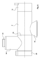
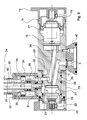
- the supplying device 1 comprises a main body 2 having at least one (cylindrical) external surface which presents a first inlet 3 (cold water inlet), a second inlet 4 (hot water inlet), a third inlet 5 (treated water inlet), a first outlet 6 (mixed water outlet) and a second outlet 7 (treated water outlet).
- the main body 2 can define, particularly, a first tap seat 8 (mixing tap seat) and a second tap seat 9 (treated water adjusting tap seat).
- the main body 2 can have, for example, a first conduit 10 (cold water conduit) therein, which is arranged to connect the first inlet 3 to the first tap seat 8.
- the main body 2 can have, for example, a second conduit 11 (hot water conduit) therein, which is arranged to connect the second inlet 4 to the first tap seat 8.
- the main body 2 can have, for example, a third conduit 12 (treated water conduit) therein, which is arranged to connect the third inlet 5 to the second tap seat 9.
- the first tap seat 8 can be, particularly, in fluid communication (directly, without the interposition of valve means or other flow-adjusting means) with the first outlet 6.
- the second tap seat 9 can be, particularly, in fluid communication (directly, without the interposition of valve means or other flow-adjusting means) with the second outlet 7.
- the two tap seats 8 and 9 can be, as in this example, arranged at the opposite ends of a longitudinal axis of the main body 2.
- the supplying device 1 can comprise a first tap 13 (particularly, a mixing tap for at least two streams) arranged in the first tap seat 8 and/or a second (flow-adjusting) tap 14 arranged in the second tap seat 9.
- Each tap 13 or 14 can have a control axis, particularly a rotation axis, by means of which a user can control the supply/mixing operations.
- the taps 13 and 14 can have two control axes parallel to each other. In this particular case, the two taps 13 and 14 have control axes which are co-axial or coincident with each other.
- the first tap 13 can comprise, as in this example, a control handle 15 for the mixed water and a mixing-adjustment cartridge 16 rotatably coupled with the first tap seat 8.
- the cartridge 16 can be fastened to the main body 2 by means of a ring nut 17 and to the control handle 15 by means of a dowel 18 with the interposition of a cartridge cap 19.
- the second tap 14 can comprise, as in this example, a control handle 20 for the treated (purified) water and a stream-adjustment (ceramic) headwork 21 coupled with the second tap seat 9.
- the control handle 20 of the treated water can be fastened to the ceramic headwork 21 through a dowel 22.
- the supplying device 1 can comprise a rotatable bush 23 arranged to carry a tilting supply barrel 24.
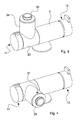
- the rotatable (barrel-holding) bush 23 can rotate about the main body 2 between at least a first angular position ( Fig. 1 ) and a second angular position ( Fig. 2 ) at which positions the tilting barrel 24 takes at least a first raised position ( Fig. 1 ) and a second lowered position ( Fig. 2 ), respectively.
- the rotatable bush 23 can be locked to the main body 2 by means of a ring nut 25.
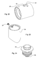
- the bush 23 has a (cylindrical) side wall which has at least two distinct (through) holes, wherein a first hole 41 (for example, ovoid- or elongated-shaped) is passed through by the cold/hot water mixture, and a second hole 42 (for example, having a circular shape) is passed through by the treated water.
- the supplying device 1 can comprise at least one first chamber 26 and at least one second chamber 27 which are defined between the bush 23 and the main body 2.
- the first and second chambers 26 and 27 can be in fluid communication with the first hole 41 and second hole 42, respectively.
- the first and second chamber 26 and 27 can be in fluid communication with the first outlet 6 and second outlet 7, respectively.
- the two chambers 26 and 27 can be in fluid communication with the two outlets 6 and 7, respectively, in all the angular positions taken by the bush 23 while rotating between the first and second angular positions.
- the two outlets 6 and 7 provided on the main body 2 can be in fluid communication with the two holes 41 and 42 provided on the bush 23 in all the angular positions taken by the bush 23 while rotating between the first and second angular positions, thereby allowing the mixture stream and/or the treated water stream to be supplied irrespectively of the position of the tilting barrel between the first raised position and the second lowered position.
- the supplying device 1 can comprise sealing means 28 (for example, an O-ring) which are arranged to provide a sealing between the bush 23 and main body 2 in a sealing area comprised between the first chamber 26 and second chamber 27.
- sealing means 28 for example, an O-ring
- the supplying device 1 can comprise, as stated above, a tilting supply barrel 24 carried by the bush 23 with the possibility of taking the first raised position and the second lowered position (whereas the rotatable bush, while rotating, takes the first angular position and second angular position).
- the supply barrel 24 can be in fluid communication with the first chamber 26 and/or second chamber 27, particularly in all the positions comprised between the first raised position and the second lowered position.
- the supplying device 1 can comprise signaling means (for example, of the snap type) to signal when the bush 23 (and consequently the barrel 24 as well) is in at least one set angular position relative to the main body 2, particularly to signal when the barrel 24 is in a predetermined desired position (for example, in an upright raised position).
- signaling means can comprise, for example, elastic snap engaging means arranged between the main body 2 and the bush 23 only to intervene in one (or more than one) set angular position.
- these engagement means can comprise an elastic pin 29 arranged in a recess 43 (of the main body 2, as in this case, or of the bush 23) and having a (rounded) end which can be inserted in a notch (on the bush 23, as in this case, or on the main body 2) in the preset angular position in which the notch results to be directly facing the elastic pin 29.
- the snap of the pin 29, which is due to the pin end being inserted in the notch while the bush 23 rotates, determines a signal that is perceived by the user when the barrel 24 is in the desired position.
- This signal can comprise an acoustic signal (the snap sound) and/or a mechanical signal provided by the (slight) mechanical resistance to the rotation which the user perceives, while he rotates the barrel 24, upon the pin 29 being engaged in the notch.
- the elastic pin 29 can be disengaged from the notch by re-entering the inside of the recess 43 (in the main body 2), by means of a slight effort exerted by the user rotating the barrel 24 (in either direction) around the axis of rotation of the bush 23.
- the supplying device 1 can comprise connecting means interposed between the rotatable bush 23 and the tilting barrel 24.
- This connecting means can define, as in the specific example, a central conduit 30 and a peripheral (annular) conduit 31 having inside at least one part of the central conduit 30.
- the connecting means comprise a manifold conduit 32 coupled to the tilting barrel 24.
- the tilting barrel 24 is defined by two tubular elements, which are co-axially arranged one inside the other.
- the two tubular elements define two distinct supply conduits which are co-axially arranged one inside the other and separated from each other, which allow the mixed water and treated water, respectively, to separately flow along two respective distinct and separated dispensing paths.
- the barrel 24 comprises a first more internal tubular conduit 60, in fluid communication with the central conduit 30, which is intended to be passed through only by the treated water.
- the barrel 24 further comprises a second external co-axial conduit 61, in fluid communication only with said peripheral (annular) conduit 31, which is intended to be passed through only by the mixed water.
- the mixed water and the treated water can thus flow along distinct and separated dispensing paths until they reach two respective outlet mouths at the end of the barrel 24.
- the central conduit 30 can be in fluid communication with one of the two outlets (the second outlet 7 in the specific case) and with one of the two holes on the bush (the second hole 42 in the specific case); the peripheral conduit 31 can be in fluid communication with the other of the two outlets (the first outlet 6 in the specific case) and with the other of the two holes on the bush (the first hole 41 in the specific case).
- connection means can comprise, as in the specific example, a (rotatable) barrel-holding connection 33 to which an end of the barrel 24 is fastened (for example, by means of a screw coupling).
- the barrel-holding connection 33 can be rotatable about a rotation axis (parallel to at least one straight portion of the barrel 24) in order to allow the barrel 24 to rotate on itself.
- the barrel-holding connection 33 can be rotatably mounted to a barrel-holding shank 34 (integrally rotatable with the bush 23) which can be, in turn, fastened to the bush 23 by means of a connection for the shank 35 (for example, provided with screw coupling means).
- the barrel-holding connection 33 can be particularly provided with a (central, for example cylindrical) portion 36 rotatably coupled within a (cylindrical) seat of the shank connection 35.
- the barrel-holding connection 33 can be fastened to the barrel-holding shank 34 by means, for example, a locking screw 37 that can be engaged in an (annular) groove 38 provided on the outside of the barrel-holding connection 33.
- the central conduit 30 can be provided, for example, at least partially in the shank connection 35 and/or in the barrel-holding connection portion 36 which is rotatably coupled to the barrel-holding connection 33.
- the manifold conduit 32 can be provided, for example, at least partially in the barrel-holding connection 33.
- the peripheral conduit 31 can be provided, for example, at least partially, in an annular space comprised between the barrel-holding shank 34 and the shank connection 35 and/or in an (annular) fluid passage area interposed between the central portion 36 of the barrel-holding connection and a peripheral (annular) portion of the barrel-holding connection 33.
- Sealing means can be provided (for example, one or more O-rings) operating between said peripheral portion (annular) of the barrel-holding connection 33 and the barrel-holding shank 34.
- the first chamber 26 and/or the second chamber 27 extend in length, particularly, each at least partially developing as a circumference arc co-axial with the axis of rotation of the bush 23 rotatable about the main body 2.
- the first chamber 26 can be defined, as in this case, by a recessed groove provided in an internal cylindrical surface of the bush 23 and facing a cylindrical surface of the main body 2.
- the second chamber 27 can also be defined as a recessed groove provided in an internal cylindrical surface of the bush 23 and facing a cylindrical surface of the main body 2.
- the supplying device 1 can comprise a fourth conduit 39 arranged inside the main body 2 in order to connect the first tap seat 8 (in the cold/hot water mixing area) to the first outlet 6.
- the fourth conduit 39 can have, as in this case, at least one (straight) portion that is alongside, for example in a substantially parallel manner, to at least one (straight) portion of the third conduit 12.
- the fourth conduit 39 can have, particularly, at least one oblique portion starting from the first tap seat 8 and being arranged obliquely relative to a control axis of the first tap 13.
- the third conduit 12 can have, as in this example, at least one oblique portion which ends in the second tap seat 9 and which is obliquely arranged relative to a control axis of the second tap 14.
- the first chamber 26 and the second chamber 27 can be in fluid communication, respectively, with the first outlet 6 and with the second outlet 7, in all the angular positions taken by the bush 23 and comprised between the first angular position and the second angular position.
- the main body 2 can be integrally provided in one piece and/or the rotatable bush 23 can be integrally provided in one piece.
- the supplying device 1 can have, as in the example described herein, a base 40 fastened to the main body 2 (for example, by means of screw fixing means) and having inside three conduits connected to the supply of the three liquids to be supplied/mixed (cold water, hot water, treated water).
- first hole 41 and the second hole 42 can be seen, which are provided in a (side, for example cylindrical) wall of the bush 23.
- the device described herein is an example of a supplying device with tilting barrel which allows the selective supply of a mixture of two liquids (cold water and hot water) and a third liquid (treated water).
Landscapes
- Engineering & Computer Science (AREA)
- General Engineering & Computer Science (AREA)
- Public Health (AREA)
- Health & Medical Sciences (AREA)
- Life Sciences & Earth Sciences (AREA)
- Hydrology & Water Resources (AREA)
- Mechanical Engineering (AREA)
- Water Supply & Treatment (AREA)
- Multiple-Way Valves (AREA)
- Processing Of Meat And Fish (AREA)
- Crystals, And After-Treatments Of Crystals (AREA)
- Fish Paste Products (AREA)
- Devices For Dispensing Beverages (AREA)
Applications Claiming Priority (1)
| Application Number | Priority Date | Filing Date | Title |
|---|---|---|---|
| IT002072A ITMI20132072A1 (it) | 2013-12-12 | 2013-12-12 | Dispositivo di erogazione con canna abbattibile |
Publications (2)
| Publication Number | Publication Date |
|---|---|
| EP2884012A1 true EP2884012A1 (fr) | 2015-06-17 |
| EP2884012B1 EP2884012B1 (fr) | 2016-11-30 |
Family
ID=50073297
Family Applications (1)
| Application Number | Title | Priority Date | Filing Date |
|---|---|---|---|
| EP14197737.1A Active EP2884012B1 (fr) | 2013-12-12 | 2014-12-12 | Dispositif d'alimentation avec canon oscillant |
Country Status (3)
| Country | Link |
|---|---|
| EP (1) | EP2884012B1 (fr) |
| DK (1) | DK2884012T3 (fr) |
| IT (1) | ITMI20132072A1 (fr) |
Cited By (7)
| Publication number | Priority date | Publication date | Assignee | Title |
|---|---|---|---|---|
| CN106894473A (zh) * | 2015-12-21 | 2017-06-27 | 汉斯格罗欧洲公司 | 卫生的出水口配件 |
| ITUB20161165A1 (it) * | 2016-02-29 | 2017-08-29 | Ib Rubinetterie S P A | Gruppo miscelatore erogatore monocomando |
| EP3269883A1 (fr) * | 2016-07-15 | 2018-01-17 | GM Rubinetterie S.r.l. | Robinet avec dispositif de traitement d'eau pour le montage mural |
| EP3351694A1 (fr) * | 2017-01-11 | 2018-07-25 | Kohler Co. | Robinet à commandes multidirectionnelles |
| CN109522638A (zh) * | 2018-12-14 | 2019-03-26 | 中国航发贵州红林航空动力控制科技有限公司 | 一种分圈分压式计量活门衬套型孔结构及设计方法 |
| IT201800011074A1 (it) | 2018-12-13 | 2020-06-13 | Vizio Gmbh | Dispositivo di erogazione |
| IT201900024310A1 (it) | 2019-12-17 | 2021-06-17 | Vizio Gmbh | Dispositivo di erogazione |
Citations (7)
| Publication number | Priority date | Publication date | Assignee | Title |
|---|---|---|---|---|
| EP0200895A2 (fr) | 1985-03-26 | 1986-11-12 | Holzer, Walter, Senator h.c. Dr.h.c.Ing. | Dispositif et procédé d'actionnement d'un robinet d'eau |
| EP0577164A1 (fr) | 1992-06-02 | 1994-01-05 | TELMA GUZZINI S.r.l. | Soupape de double manoeuvre avec sélecteur |
| DE202004005561U1 (de) | 2004-04-07 | 2004-07-01 | Reich Kg, Regel- Und Sicherheitstechnik | Wasserauslaufarmatur |
| EP1491805A1 (fr) | 2003-06-10 | 2004-12-29 | Gallazzini S.p.A. | Robinet à commande unique |
| WO2006072250A1 (fr) | 2005-01-05 | 2006-07-13 | Damixa Aps | Robinet melangeur |
| EP2472150A1 (fr) | 2010-12-30 | 2012-07-04 | GM Rubinetterie S.r.l. | Système et unité de soupape |
| EP2672027A1 (fr) | 2012-06-04 | 2013-12-11 | Daalderop B.V. | Robinet pour eau chaude, froide et préparée |
-
2013
- 2013-12-12 IT IT002072A patent/ITMI20132072A1/it unknown
-
2014
- 2014-12-12 DK DK14197737.1T patent/DK2884012T3/en active
- 2014-12-12 EP EP14197737.1A patent/EP2884012B1/fr active Active
Patent Citations (7)
| Publication number | Priority date | Publication date | Assignee | Title |
|---|---|---|---|---|
| EP0200895A2 (fr) | 1985-03-26 | 1986-11-12 | Holzer, Walter, Senator h.c. Dr.h.c.Ing. | Dispositif et procédé d'actionnement d'un robinet d'eau |
| EP0577164A1 (fr) | 1992-06-02 | 1994-01-05 | TELMA GUZZINI S.r.l. | Soupape de double manoeuvre avec sélecteur |
| EP1491805A1 (fr) | 2003-06-10 | 2004-12-29 | Gallazzini S.p.A. | Robinet à commande unique |
| DE202004005561U1 (de) | 2004-04-07 | 2004-07-01 | Reich Kg, Regel- Und Sicherheitstechnik | Wasserauslaufarmatur |
| WO2006072250A1 (fr) | 2005-01-05 | 2006-07-13 | Damixa Aps | Robinet melangeur |
| EP2472150A1 (fr) | 2010-12-30 | 2012-07-04 | GM Rubinetterie S.r.l. | Système et unité de soupape |
| EP2672027A1 (fr) | 2012-06-04 | 2013-12-11 | Daalderop B.V. | Robinet pour eau chaude, froide et préparée |
Cited By (13)
| Publication number | Priority date | Publication date | Assignee | Title |
|---|---|---|---|---|
| CN106894473B (zh) * | 2015-12-21 | 2020-06-05 | 汉斯格罗欧洲公司 | 卫生的出水口配件 |
| EP3184704A1 (fr) * | 2015-12-21 | 2017-06-28 | Hansgrohe SE | Robinetterie sanitaire |
| CN106894473A (zh) * | 2015-12-21 | 2017-06-27 | 汉斯格罗欧洲公司 | 卫生的出水口配件 |
| ITUB20161165A1 (it) * | 2016-02-29 | 2017-08-29 | Ib Rubinetterie S P A | Gruppo miscelatore erogatore monocomando |
| EP3269883A1 (fr) * | 2016-07-15 | 2018-01-17 | GM Rubinetterie S.r.l. | Robinet avec dispositif de traitement d'eau pour le montage mural |
| US10927967B2 (en) | 2017-01-11 | 2021-02-23 | Kohler Co. | Faucet with multi-directional controls |
| US10184575B2 (en) | 2017-01-11 | 2019-01-22 | Kohler Co. | Faucet with multi-directional controls |
| EP3351694A1 (fr) * | 2017-01-11 | 2018-07-25 | Kohler Co. | Robinet à commandes multidirectionnelles |
| US12038092B2 (en) | 2017-01-11 | 2024-07-16 | Kohler Co. | Faucet with multi-directional controls |
| IT201800011074A1 (it) | 2018-12-13 | 2020-06-13 | Vizio Gmbh | Dispositivo di erogazione |
| CN109522638A (zh) * | 2018-12-14 | 2019-03-26 | 中国航发贵州红林航空动力控制科技有限公司 | 一种分圈分压式计量活门衬套型孔结构及设计方法 |
| CN109522638B (zh) * | 2018-12-14 | 2022-12-06 | 中国航发贵州红林航空动力控制科技有限公司 | 一种分圈分压式计量活门衬套型孔结构及设计方法 |
| IT201900024310A1 (it) | 2019-12-17 | 2021-06-17 | Vizio Gmbh | Dispositivo di erogazione |
Also Published As
| Publication number | Publication date |
|---|---|
| DK2884012T3 (en) | 2017-02-27 |
| EP2884012B1 (fr) | 2016-11-30 |
| ITMI20132072A1 (it) | 2015-06-13 |
Similar Documents
| Publication | Publication Date | Title |
|---|---|---|
| EP2884012B1 (fr) | Dispositif d'alimentation avec canon oscillant | |
| US10655310B2 (en) | Shower bar system | |
| US20070235091A1 (en) | Water tap assembly having a pull-out water-discharge head | |
| US10718439B2 (en) | Water tap body and installation | |
| CN103574097A (zh) | 单杆混合水龙头 | |
| US7775462B2 (en) | Spray device | |
| US12006669B2 (en) | Bridge-style faucet for single-hole installation | |
| CN108779866A (zh) | 冷热水混合水栓 | |
| US7082626B2 (en) | Diverter assembly for roman tub | |
| JP5577929B2 (ja) | 湯水混合水栓 | |
| CA2979011A1 (fr) | Raccord d'ecoulement double variable | |
| US11396740B2 (en) | Independent control free standing bath filler | |
| CN210106676U (zh) | 一种龙头 | |
| KR20220011565A (ko) | 정수필터 내장형 욕조수전 | |
| US7406984B2 (en) | Fluid distribution device | |
| US8939175B2 (en) | Fluid delivery systems | |
| JP2009287358A (ja) | 弁体と流量制御弁 | |
| JP2016050408A (ja) | 止水栓及び水栓装置 | |
| CN211599632U (zh) | 一种双出水龙头 | |
| JP2006169762A (ja) | 分岐接続具 | |
| CN110094551B (zh) | 一种龙头 | |
| CN109812600A (zh) | 水龙头 | |
| JPH0712671U (ja) | 湯水混合栓 | |
| TWI571299B (zh) | Can be drinking drink faucet structure | |
| EP3390733B1 (fr) | Accessoires de plomberie |
Legal Events
| Date | Code | Title | Description |
|---|---|---|---|
| PUAI | Public reference made under article 153(3) epc to a published international application that has entered the european phase |
Free format text: ORIGINAL CODE: 0009012 |
|
| 17P | Request for examination filed |
Effective date: 20141212 |
|
| AK | Designated contracting states |
Kind code of ref document: A1 Designated state(s): AL AT BE BG CH CY CZ DE DK EE ES FI FR GB GR HR HU IE IS IT LI LT LU LV MC MK MT NL NO PL PT RO RS SE SI SK SM TR |
|
| AX | Request for extension of the european patent |
Extension state: BA ME |
|
| R17P | Request for examination filed (corrected) |
Effective date: 20151216 |
|
| RAX | Requested extension states of the european patent have changed |
Extension state: BA Payment date: 20151216 Extension state: ME |
|
| RBV | Designated contracting states (corrected) |
Designated state(s): AL AT BE BG CH CY CZ DE DK EE ES FI FR GB GR HR HU IE IS IT LI LT LU LV MC MK MT NL NO PL PT RO RS SE SI SK SM TR |
|
| GRAP | Despatch of communication of intention to grant a patent |
Free format text: ORIGINAL CODE: EPIDOSNIGR1 |
|
| RAP1 | Party data changed (applicant data changed or rights of an application transferred) |
Owner name: GM RUBINETTERIE S.R.L. |
|
| INTG | Intention to grant announced |
Effective date: 20160621 |
|
| RIN1 | Information on inventor provided before grant (corrected) |
Inventor name: GIOIRA, MARCO Inventor name: GIOIRA, LUIGI |
|
| GRAS | Grant fee paid |
Free format text: ORIGINAL CODE: EPIDOSNIGR3 |
|
| GRAA | (expected) grant |
Free format text: ORIGINAL CODE: 0009210 |
|
| AK | Designated contracting states |
Kind code of ref document: B1 Designated state(s): AL AT BE BG CH CY CZ DE DK EE ES FI FR GB GR HR HU IE IS IT LI LT LU LV MC MK MT NL NO PL PT RO RS SE SI SK SM TR |
|
| AX | Request for extension of the european patent |
Extension state: BA |
|
| REG | Reference to a national code |
Ref country code: CH Ref legal event code: EP Ref country code: GB Ref legal event code: FG4D |
|
| REG | Reference to a national code |
Ref country code: AT Ref legal event code: REF Ref document number: 849936 Country of ref document: AT Kind code of ref document: T Effective date: 20161215 |
|
| REG | Reference to a national code |
Ref country code: IE Ref legal event code: FG4D |
|
| REG | Reference to a national code |
Ref country code: DE Ref legal event code: R096 Ref document number: 602014005182 Country of ref document: DE |
|
| REG | Reference to a national code |
Ref country code: CH Ref legal event code: PCOW Free format text: NEW ADDRESS: C/O COLOBERTI E LUPPI S.R.L. VIA E. DE AMICIS 25, 20123 MILANO (IT) |
|
| REG | Reference to a national code |
Ref country code: FR Ref legal event code: PLFP Year of fee payment: 3 |
|
| REG | Reference to a national code |
Ref country code: DK Ref legal event code: T3 Effective date: 20170221 |
|
| PG25 | Lapsed in a contracting state [announced via postgrant information from national office to epo] |
Ref country code: LV Free format text: LAPSE BECAUSE OF FAILURE TO SUBMIT A TRANSLATION OF THE DESCRIPTION OR TO PAY THE FEE WITHIN THE PRESCRIBED TIME-LIMIT Effective date: 20161130 |
|
| REG | Reference to a national code |
Ref country code: NL Ref legal event code: FP |
|
| REG | Reference to a national code |
Ref country code: LT Ref legal event code: MG4D |
|
| REG | Reference to a national code |
Ref country code: NO Ref legal event code: T2 Effective date: 20161130 |
|
| REG | Reference to a national code |
Ref country code: NO Ref legal event code: T2 Effective date: 20161130 |
|
| REG | Reference to a national code |
Ref country code: AT Ref legal event code: MK05 Ref document number: 849936 Country of ref document: AT Kind code of ref document: T Effective date: 20161130 |
|
| PG25 | Lapsed in a contracting state [announced via postgrant information from national office to epo] |
Ref country code: LT Free format text: LAPSE BECAUSE OF FAILURE TO SUBMIT A TRANSLATION OF THE DESCRIPTION OR TO PAY THE FEE WITHIN THE PRESCRIBED TIME-LIMIT Effective date: 20161130 Ref country code: SE Free format text: LAPSE BECAUSE OF FAILURE TO SUBMIT A TRANSLATION OF THE DESCRIPTION OR TO PAY THE FEE WITHIN THE PRESCRIBED TIME-LIMIT Effective date: 20161130 Ref country code: GR Free format text: LAPSE BECAUSE OF FAILURE TO SUBMIT A TRANSLATION OF THE DESCRIPTION OR TO PAY THE FEE WITHIN THE PRESCRIBED TIME-LIMIT Effective date: 20170301 |
|
| PG25 | Lapsed in a contracting state [announced via postgrant information from national office to epo] |
Ref country code: PL Free format text: LAPSE BECAUSE OF FAILURE TO SUBMIT A TRANSLATION OF THE DESCRIPTION OR TO PAY THE FEE WITHIN THE PRESCRIBED TIME-LIMIT Effective date: 20161130 Ref country code: ES Free format text: LAPSE BECAUSE OF FAILURE TO SUBMIT A TRANSLATION OF THE DESCRIPTION OR TO PAY THE FEE WITHIN THE PRESCRIBED TIME-LIMIT Effective date: 20161130 Ref country code: RS Free format text: LAPSE BECAUSE OF FAILURE TO SUBMIT A TRANSLATION OF THE DESCRIPTION OR TO PAY THE FEE WITHIN THE PRESCRIBED TIME-LIMIT Effective date: 20161130 Ref country code: HR Free format text: LAPSE BECAUSE OF FAILURE TO SUBMIT A TRANSLATION OF THE DESCRIPTION OR TO PAY THE FEE WITHIN THE PRESCRIBED TIME-LIMIT Effective date: 20161130 Ref country code: PT Free format text: LAPSE BECAUSE OF FAILURE TO SUBMIT A TRANSLATION OF THE DESCRIPTION OR TO PAY THE FEE WITHIN THE PRESCRIBED TIME-LIMIT Effective date: 20170330 Ref country code: AT Free format text: LAPSE BECAUSE OF FAILURE TO SUBMIT A TRANSLATION OF THE DESCRIPTION OR TO PAY THE FEE WITHIN THE PRESCRIBED TIME-LIMIT Effective date: 20161130 |
|
| PG25 | Lapsed in a contracting state [announced via postgrant information from national office to epo] |
Ref country code: SK Free format text: LAPSE BECAUSE OF FAILURE TO SUBMIT A TRANSLATION OF THE DESCRIPTION OR TO PAY THE FEE WITHIN THE PRESCRIBED TIME-LIMIT Effective date: 20161130 Ref country code: EE Free format text: LAPSE BECAUSE OF FAILURE TO SUBMIT A TRANSLATION OF THE DESCRIPTION OR TO PAY THE FEE WITHIN THE PRESCRIBED TIME-LIMIT Effective date: 20161130 Ref country code: CZ Free format text: LAPSE BECAUSE OF FAILURE TO SUBMIT A TRANSLATION OF THE DESCRIPTION OR TO PAY THE FEE WITHIN THE PRESCRIBED TIME-LIMIT Effective date: 20161130 Ref country code: RO Free format text: LAPSE BECAUSE OF FAILURE TO SUBMIT A TRANSLATION OF THE DESCRIPTION OR TO PAY THE FEE WITHIN THE PRESCRIBED TIME-LIMIT Effective date: 20161130 |
|
| PG25 | Lapsed in a contracting state [announced via postgrant information from national office to epo] |
Ref country code: BG Free format text: LAPSE BECAUSE OF FAILURE TO SUBMIT A TRANSLATION OF THE DESCRIPTION OR TO PAY THE FEE WITHIN THE PRESCRIBED TIME-LIMIT Effective date: 20170228 Ref country code: SM Free format text: LAPSE BECAUSE OF FAILURE TO SUBMIT A TRANSLATION OF THE DESCRIPTION OR TO PAY THE FEE WITHIN THE PRESCRIBED TIME-LIMIT Effective date: 20161130 |
|
| REG | Reference to a national code |
Ref country code: DE Ref legal event code: R097 Ref document number: 602014005182 Country of ref document: DE |
|
| PG25 | Lapsed in a contracting state [announced via postgrant information from national office to epo] |
Ref country code: MC Free format text: LAPSE BECAUSE OF FAILURE TO SUBMIT A TRANSLATION OF THE DESCRIPTION OR TO PAY THE FEE WITHIN THE PRESCRIBED TIME-LIMIT Effective date: 20161130 |
|
| REG | Reference to a national code |
Ref country code: IE Ref legal event code: MM4A |
|
| PLBE | No opposition filed within time limit |
Free format text: ORIGINAL CODE: 0009261 |
|
| STAA | Information on the status of an ep patent application or granted ep patent |
Free format text: STATUS: NO OPPOSITION FILED WITHIN TIME LIMIT |
|
| 26N | No opposition filed |
Effective date: 20170831 |
|
| REG | Reference to a national code |
Ref country code: FR Ref legal event code: PLFP Year of fee payment: 4 |
|
| PG25 | Lapsed in a contracting state [announced via postgrant information from national office to epo] |
Ref country code: SI Free format text: LAPSE BECAUSE OF FAILURE TO SUBMIT A TRANSLATION OF THE DESCRIPTION OR TO PAY THE FEE WITHIN THE PRESCRIBED TIME-LIMIT Effective date: 20161130 Ref country code: IE Free format text: LAPSE BECAUSE OF NON-PAYMENT OF DUE FEES Effective date: 20161212 |
|
| PG25 | Lapsed in a contracting state [announced via postgrant information from national office to epo] |
Ref country code: HU Free format text: LAPSE BECAUSE OF FAILURE TO SUBMIT A TRANSLATION OF THE DESCRIPTION OR TO PAY THE FEE WITHIN THE PRESCRIBED TIME-LIMIT; INVALID AB INITIO Effective date: 20141212 |
|
| PG25 | Lapsed in a contracting state [announced via postgrant information from national office to epo] |
Ref country code: MK Free format text: LAPSE BECAUSE OF FAILURE TO SUBMIT A TRANSLATION OF THE DESCRIPTION OR TO PAY THE FEE WITHIN THE PRESCRIBED TIME-LIMIT Effective date: 20161130 Ref country code: IS Free format text: LAPSE BECAUSE OF FAILURE TO SUBMIT A TRANSLATION OF THE DESCRIPTION OR TO PAY THE FEE WITHIN THE PRESCRIBED TIME-LIMIT Effective date: 20161130 Ref country code: CY Free format text: LAPSE BECAUSE OF FAILURE TO SUBMIT A TRANSLATION OF THE DESCRIPTION OR TO PAY THE FEE WITHIN THE PRESCRIBED TIME-LIMIT Effective date: 20161130 |
|
| PG25 | Lapsed in a contracting state [announced via postgrant information from national office to epo] |
Ref country code: MT Free format text: LAPSE BECAUSE OF NON-PAYMENT OF DUE FEES Effective date: 20161212 |
|
| PG25 | Lapsed in a contracting state [announced via postgrant information from national office to epo] |
Ref country code: TR Free format text: LAPSE BECAUSE OF FAILURE TO SUBMIT A TRANSLATION OF THE DESCRIPTION OR TO PAY THE FEE WITHIN THE PRESCRIBED TIME-LIMIT Effective date: 20161130 |
|
| PG25 | Lapsed in a contracting state [announced via postgrant information from national office to epo] |
Ref country code: AL Free format text: LAPSE BECAUSE OF FAILURE TO SUBMIT A TRANSLATION OF THE DESCRIPTION OR TO PAY THE FEE WITHIN THE PRESCRIBED TIME-LIMIT Effective date: 20161130 |
|
| PGFP | Annual fee paid to national office [announced via postgrant information from national office to epo] |
Ref country code: GB Payment date: 20231227 Year of fee payment: 10 |
|
| PGFP | Annual fee paid to national office [announced via postgrant information from national office to epo] |
Ref country code: NO Payment date: 20231227 Year of fee payment: 10 Ref country code: NL Payment date: 20231226 Year of fee payment: 10 Ref country code: LU Payment date: 20231227 Year of fee payment: 10 Ref country code: IT Payment date: 20231220 Year of fee payment: 10 Ref country code: FR Payment date: 20231227 Year of fee payment: 10 Ref country code: FI Payment date: 20231227 Year of fee payment: 10 Ref country code: DK Payment date: 20231229 Year of fee payment: 10 |
|
| PGFP | Annual fee paid to national office [announced via postgrant information from national office to epo] |
Ref country code: BE Payment date: 20231227 Year of fee payment: 10 |
|
| PGFP | Annual fee paid to national office [announced via postgrant information from national office to epo] |
Ref country code: DE Payment date: 20231229 Year of fee payment: 10 Ref country code: CH Payment date: 20240101 Year of fee payment: 10 |
|
| REG | Reference to a national code |
Ref country code: DE Ref legal event code: R119 Ref document number: 602014005182 Country of ref document: DE |
|
| PG25 | Lapsed in a contracting state [announced via postgrant information from national office to epo] |
Ref country code: FI Free format text: LAPSE BECAUSE OF NON-PAYMENT OF DUE FEES Effective date: 20241212 |
|
| REG | Reference to a national code |
Ref country code: DK Ref legal event code: EBP Effective date: 20241231 |
|
| REG | Reference to a national code |
Ref country code: CH Ref legal event code: PL |
|
| REG | Reference to a national code |
Ref country code: NL Ref legal event code: MM Effective date: 20250101 |
|
| PG25 | Lapsed in a contracting state [announced via postgrant information from national office to epo] |
Ref country code: LU Free format text: LAPSE BECAUSE OF NON-PAYMENT OF DUE FEES Effective date: 20241212 |
|
| GBPC | Gb: european patent ceased through non-payment of renewal fee |
Effective date: 20241212 |
|
| PG25 | Lapsed in a contracting state [announced via postgrant information from national office to epo] |
Ref country code: NL Free format text: LAPSE BECAUSE OF NON-PAYMENT OF DUE FEES Effective date: 20250101 |
|
| REG | Reference to a national code |
Ref country code: BE Ref legal event code: MM Effective date: 20241231 |
|
| PG25 | Lapsed in a contracting state [announced via postgrant information from national office to epo] |
Ref country code: DE Free format text: LAPSE BECAUSE OF NON-PAYMENT OF DUE FEES Effective date: 20250701 |
|
| PG25 | Lapsed in a contracting state [announced via postgrant information from national office to epo] |
Ref country code: IT Free format text: LAPSE BECAUSE OF NON-PAYMENT OF DUE FEES Effective date: 20241212 Ref country code: NO Free format text: LAPSE BECAUSE OF NON-PAYMENT OF DUE FEES Effective date: 20241231 |
|
| PG25 | Lapsed in a contracting state [announced via postgrant information from national office to epo] |
Ref country code: GB Free format text: LAPSE BECAUSE OF NON-PAYMENT OF DUE FEES Effective date: 20241212 Ref country code: BE Free format text: LAPSE BECAUSE OF NON-PAYMENT OF DUE FEES Effective date: 20241231 |
|
| PG25 | Lapsed in a contracting state [announced via postgrant information from national office to epo] |
Ref country code: FR Free format text: LAPSE BECAUSE OF NON-PAYMENT OF DUE FEES Effective date: 20241231 |
|
| PG25 | Lapsed in a contracting state [announced via postgrant information from national office to epo] |
Ref country code: CH Free format text: LAPSE BECAUSE OF NON-PAYMENT OF DUE FEES Effective date: 20241231 |
|
| PG25 | Lapsed in a contracting state [announced via postgrant information from national office to epo] |
Ref country code: DK Free format text: LAPSE BECAUSE OF NON-PAYMENT OF DUE FEES Effective date: 20241231 |