EP2884140A1 - Soupape de dosage pour perçage diamant - Google Patents
Soupape de dosage pour perçage diamant Download PDFInfo
- Publication number
- EP2884140A1 EP2884140A1 EP13197047.7A EP13197047A EP2884140A1 EP 2884140 A1 EP2884140 A1 EP 2884140A1 EP 13197047 A EP13197047 A EP 13197047A EP 2884140 A1 EP2884140 A1 EP 2884140A1
- Authority
- EP
- European Patent Office
- Prior art keywords
- passage opening
- blocking device
- fluid
- shut
- fluid line
- Prior art date
- Legal status (The legal status is an assumption and is not a legal conclusion. Google has not performed a legal analysis and makes no representation as to the accuracy of the status listed.)
- Withdrawn
Links
- 238000005553 drilling Methods 0.000 title description 6
- 229910003460 diamond Inorganic materials 0.000 title 1
- 239000010432 diamond Substances 0.000 title 1
- 239000012530 fluid Substances 0.000 claims abstract description 108
- 230000000903 blocking effect Effects 0.000 claims abstract description 99
- 230000002441 reversible effect Effects 0.000 claims abstract description 3
- 239000000110 cooling liquid Substances 0.000 description 10
- 239000002826 coolant Substances 0.000 description 8
- 238000001816 cooling Methods 0.000 description 7
- 239000007788 liquid Substances 0.000 description 5
- 230000001105 regulatory effect Effects 0.000 description 4
- 239000000463 material Substances 0.000 description 3
- XLYOFNOQVPJJNP-UHFFFAOYSA-N water Substances O XLYOFNOQVPJJNP-UHFFFAOYSA-N 0.000 description 3
- 239000012809 cooling fluid Substances 0.000 description 2
- 230000001419 dependent effect Effects 0.000 description 1
- 239000011435 rock Substances 0.000 description 1
- 238000010408 sweeping Methods 0.000 description 1
Images







Classifications
-
- F—MECHANICAL ENGINEERING; LIGHTING; HEATING; WEAPONS; BLASTING
- F16—ENGINEERING ELEMENTS AND UNITS; GENERAL MEASURES FOR PRODUCING AND MAINTAINING EFFECTIVE FUNCTIONING OF MACHINES OR INSTALLATIONS; THERMAL INSULATION IN GENERAL
- F16K—VALVES; TAPS; COCKS; ACTUATING-FLOATS; DEVICES FOR VENTING OR AERATING
- F16K5/00—Plug valves; Taps or cocks comprising only cut-off apparatus having at least one of the sealing faces shaped as a more or less complete surface of a solid of revolution, the opening and closing movement being predominantly rotary
- F16K5/04—Plug valves; Taps or cocks comprising only cut-off apparatus having at least one of the sealing faces shaped as a more or less complete surface of a solid of revolution, the opening and closing movement being predominantly rotary with plugs having cylindrical surfaces; Packings therefor
- F16K5/0407—Plug valves; Taps or cocks comprising only cut-off apparatus having at least one of the sealing faces shaped as a more or less complete surface of a solid of revolution, the opening and closing movement being predominantly rotary with plugs having cylindrical surfaces; Packings therefor with particular plug arrangements, e.g. particular shape or built-in means
-
- F—MECHANICAL ENGINEERING; LIGHTING; HEATING; WEAPONS; BLASTING
- F16—ENGINEERING ELEMENTS AND UNITS; GENERAL MEASURES FOR PRODUCING AND MAINTAINING EFFECTIVE FUNCTIONING OF MACHINES OR INSTALLATIONS; THERMAL INSULATION IN GENERAL
- F16K—VALVES; TAPS; COCKS; ACTUATING-FLOATS; DEVICES FOR VENTING OR AERATING
- F16K27/00—Construction of housing; Use of materials therefor
- F16K27/06—Construction of housing; Use of materials therefor of taps or cocks
- F16K27/065—Construction of housing; Use of materials therefor of taps or cocks with cylindrical plugs
-
- F—MECHANICAL ENGINEERING; LIGHTING; HEATING; WEAPONS; BLASTING
- F16—ENGINEERING ELEMENTS AND UNITS; GENERAL MEASURES FOR PRODUCING AND MAINTAINING EFFECTIVE FUNCTIONING OF MACHINES OR INSTALLATIONS; THERMAL INSULATION IN GENERAL
- F16K—VALVES; TAPS; COCKS; ACTUATING-FLOATS; DEVICES FOR VENTING OR AERATING
- F16K31/00—Actuating devices; Operating means; Releasing devices
- F16K31/44—Mechanical actuating means
- F16K31/60—Handles
- F16K31/602—Pivoting levers, e.g. single-sided
-
- F—MECHANICAL ENGINEERING; LIGHTING; HEATING; WEAPONS; BLASTING
- F16—ENGINEERING ELEMENTS AND UNITS; GENERAL MEASURES FOR PRODUCING AND MAINTAINING EFFECTIVE FUNCTIONING OF MACHINES OR INSTALLATIONS; THERMAL INSULATION IN GENERAL
- F16K—VALVES; TAPS; COCKS; ACTUATING-FLOATS; DEVICES FOR VENTING OR AERATING
- F16K5/00—Plug valves; Taps or cocks comprising only cut-off apparatus having at least one of the sealing faces shaped as a more or less complete surface of a solid of revolution, the opening and closing movement being predominantly rotary
- F16K5/08—Details
- F16K5/12—Arrangements for modifying the way in which the rate of flow varies during the actuation of the valve
Definitions
- the present invention relates to a shut-off device for at least partially blocking a fluid in a fluid line.
- the shut-off device contains a blocking device with a substantially cylindrical base body containing a first end and a second end, wherein the blocking device is positionable in the fluid line and reversible by rotating in a rotational direction about an axis of rotation of a blocking position in which no fluid through the blocking device can flow, is adjustable in a flow position in which fluid can flow through the blocking device.
- the cooling liquid is usually water.
- Such cooling systems consist essentially of a supply of cooling liquid, which is normally realized by a connection to a water line, a device (eg a pump) for conveying the cooling liquid to the tool and at least one cooling liquid line for the supply of the cooling liquid to the tool.
- the size of the supply of cooling liquid, the performance of the device for conveying the cooling liquid and the amount (volume) of supplied coolant to the tool is among other things of the material to be machined, the size and performance of the machine tool and the desired operating speed (progress of Tool in the material).
- the metering of the amount of coolant supplied to the tool for the user of the cooling system poses a recurring problem because the amount of coolant supplied should be neither too high nor too low.
- shut-off device which is usually positioned in the form of a manually operable control valve in the coolant line and controls the amount or volume of coolant to the tool.
- This commonly used as a control valve configured shut-off devices do not allow a sufficient enemy discharge of small quantities of coolant, so that either the control valve can only be completely closed or opened too far. As a result, either no coolant or too much coolant flows to the tool.
- Such a shut-off device in a liquid line is for example in the PCT patent application WO 2011/091798 disclosed.
- the WO 2011/091798 shows a discharge valve, with which the volume of a liquid flowing through the valve can be regulated.
- the drain valve includes a valve housing having an input and output port. Both at the inlet and at the outlet opening in each case a liquid line is connected.
- a plate-shaped regulating element which can be rotated by a hand element in the valve housing and serves to regulate the volume of the liquid flowing through the discharge valve.
- the plate-shaped regulating element is rotated in front of the inlet and outlet openings so that the cross-section of the flow opening at the inlet and outlet openings is reduced. Reducing the cross section reduces the amount of fluid that can pass through the drain valve.
- a shut-off device for at least partially blocking a fluid in a fluid line containing a blocking device with a substantially cylindrical base body which includes a first end and a second end, wherein the blocking device is positionable in the fluid line and by turning in a direction (A) about a rotation axis (R) is reversibly adjustable from a blocking position, in which no fluid can flow through the blocking device, into a flow position in which fluid can flow through the blocking device.
- the blocking device contains a first passage opening and a second passage opening, wherein the cross section of the first passage opening is smaller than the cross section of the second passage opening.
- the smaller cross-section of the first passage opening improves the controllability of the flow of smaller amounts of fluid through the blocking device.
- the first passage opening and the second passage opening communicate with each other via a passage opening along the lateral surface of the cylindrical base body are connected.
- the first passage opening has a substantially wedge-shaped cross-section.
- the wedge-shaped cross section of the first passage opening can be used to set the effective size of the first passage opening and thus the amount of fluid which can flow through the blocking device and to the tool.
- the wedge-shaped cross-section contains at least a first surface having a first surface edge and a second surface edge and a second surface having a first surface edge, a second surface edge and a third surface edge, wherein the first Surface parallel to the axis of rotation extends and the second surface extends at an angle to the axis of rotation, that a first end of the second surface edge and a first end of the third surface edge substantially coincide at a point at the second end of the cylindrical base body.
- the first passage opening is positioned in front of the second passage opening. This ensures that with a corresponding rotation of the blocking device in the Fluid line first fluid through the first passage opening and only upon further rotation of the blocking device flows through the second passage opening. Consequently, only a correspondingly small amount of fluid flows through the blocking device to the tool.
- the first surface of the first passage opening is positioned in front of the second surface of the first passage opening. This ensures that the enlargement of the cross section of the first passage opening by a corresponding rotation of the blocking device is always carried out by an increase with a smaller and smaller cross-sectional portion.
- the blocking device is aligned by rotation in the fluid line so that only through the first passage opening, through the first passage opening and the second passage opening or only through the second passage opening, a flow through the fluid the blocking device is possible. This ensures either a continuous or an abrupt increase in the flow volume of fluid through the blocking device.
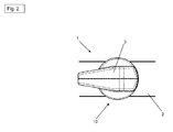
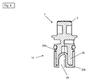
- Fig. 1 to 4 shows a shut-off device 1 for at least partially blocking a fluid (not shown) in a fluid line 2.
- the fluid may be water or another fluid.
- a gas is used.
- the shut-off device 1 may be part of a cooling or rinsing system, not shown, which can be used to cool a machine tool, not shown, with the fluid or to rinse the tool of the machine tool (eg a drill bit) and to clean it from drilling mud.
- the machine tool may be a sweeping machine or the like.
- the shut-off device 1 contains an operating element 3 and a blocking device 10 with a substantially cylindrical main body 20.
- the main body 20 has a first end 20a and a second end 20b.
- the blocking device 10 is positioned in a fluid line 2 such that the first end 20a of the main body 20 protrudes from the fluid line 2 and the second end 20b of the main body 20 is rotatably arranged in the fluid line 2 (cf. Fig. 5 and 6 ).
- the operating element 3 is configured in the form of a rotary lever and positioned at the first end 20 a of the cylindrical base body 20. Trained as a rotary lever control element 3 serves to rotate the blocking device 10 in the fluid line 2 or align.
- the blocking device 10 is positioned in a fluid line 2 to control the flow of the fluid, i. E., Depending on the position of the blocking device 10 in the fluid line 2. a liquid or gas, to block or release. Thereby, the amount of fluid flowing through the blocking device 10 and to the machine tool can be regulated.
- the fluid is not shown in the figures.
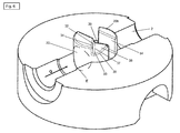
- the cylindrical basic body 20 of the blocking device 10 contains a first passage opening 30 and a second passage opening 50 (cf. Fig. 5 and 6 ).
- Both the first passage opening 30 and the second passage opening 50 include a passage through the cylindrical base body 20 of the blocking device 10, through which the fluid can flow.
- the cross section of the first passage opening 30 is smaller than the cross section of the second passage opening 50, whereby a small volume of fluid per unit time can flow through the first (smaller) passage opening 30.
- the first passage opening 30 contains a substantially wedge-shaped cross section, whereby the first passage opening 30 along the bottom of the cylindrical base body 20 has a first surface 32 and a second surface 36.
- the first surface 32 contains
- the second surface 36 has a first surface edge 37, a second surface edge 38, and a third surface edge 39.
- the second surface 36 thus substantially contains a triangular shape (cf. Fig. 5 . 6 and 18 ).
- the first surface edge 33 of the first surface 32 adjoins the first surface edge 37 of the second surface 36.
- the second surface edge 38 of the second surface 36 extends along the lateral surface of the cylindrical base body 20.
- the third surface edge 39 of the second surface 36 extends along the second passage opening 50.
- the second passage opening 50 includes a substantially rectangular cross-section having a first wall surface 52, a second wall surface 54 and a third wall surface 56.
- the first wall surface 52 and the second wall surface 54 face each other.
- the third wall surface 56 is configured substantially in an arc shape and connects the first wall surface 52 with the second wall surface 54.
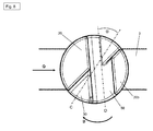
- the first through hole 30 crosses the second through hole 50. As in FIG Fig. 8 2, the center line C of the first through hole 30 crosses the center line D of the second through hole 50 at an obtuse angle ( ⁇ ).
- the shut-off device 1 is rotatably positioned on the fluid line 2.
- the blocking device 10 is thereby rotatably mounted in the fluid line 2.
- the blocking device 10 is aligned in the fluid line 2 accordingly.
- the respective rotational position of the blocking device 10 either a larger or smaller cross-section of the first passage opening 30 for the fluid for flowing through the blocking device 10 is released.
- the blocking device 10 may also be completely blocked, so that no fluid can flow through the blocking device 10.
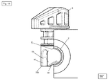
- Fig. 15 it is also possible in a corresponding rotational position (55 ° position) of the blocking device 10 that the fluid flows through both the first passage opening 30 and through the second passage opening 50.
- the first passage opening 30 is connected to the second passage opening 50 through a passage opening (not shown).
- a faster increase in the flow volume of the fluid per unit time can be achieved by the blocking device, since the cross section of the first passage opening 30 through a corresponding alignment of the blocking device 10 in the fluid line 2 is increased faster than without additional passage opening.
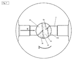
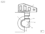
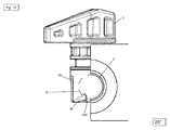
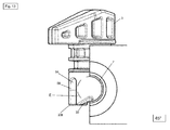
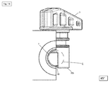
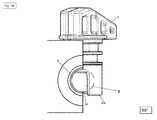
- FIGS. 9 to 18 are different rotational positions of the blocking device 10 shown in the fluid line 2.
- the circle E indicates in each case the contact surface of the fluid line 2 to the blocking device 10 (see. Fig. 5 . 6 . 9 to 18 ).
- the subsequent degree positions refer to the respective rotation of the blocking device 10 in the fluid line 2 in degrees (°) with respect to the starting position (0 °), in which the blocking device 10 is completely closed, ie no fluid flow through the blocking device 10 can.
- To open the blocking device 10 in the fluid line 2 in the blocking device 10 in the direction B see. Fig. 5 . 7 . 8th ) turned.
- Fig. 9 is the view in the flow direction Q of the fluid through the fluid line.
- Fig. 10 is the view opposite to the flow direction Q of the fluid through the fluid line. 2
- the blocking device 10 is in a 25 ° position, so that the first passage opening 30 can be opened and a little fluid can flow through the blocking device 10.
- Fig. 11 is the view in the flow direction Q of the fluid through the fluid line.
- Fig. 12 is the view opposite to the flow direction Q of the fluid through the fluid line 2.
- the blocking device 10 is in a 45 ° position in which the first passage opening 30 is opened a little further and a little more fluid per unit time can flow through the blocking device 10.
- Fig. 13 is the view in the flow direction Q of the fluid through the fluid line.
- Fig. 14 is the view opposite to the flow direction Q of the fluid through the fluid line. 2
- the blocking device 10 is in a 55 ° position in which the first passage opening 30 is opened to the maximum.
- Fig. 15 is the view in the flow direction Q of the fluid through the fluid line.
- Fig. 16 is the view opposite to the flow direction Q of the fluid through the fluid line. 2
- the blocking device 10 is in a 90 ° position, in which the second passage opening 50 is opened maximum and the first passage opening 30 is in turn closed. In this 90 ° position, the maximum volume of fluid per unit time flows through the blocking device 10.
- Fig. 17 is the view in the flow direction Q of Fluids through the fluid line.
- Fig. 18 is the view opposite to the flow direction Q of the fluid through the fluid line. 2
- the amount of fluid that flows through the blocking device 10 and is conveyed to the machine tool for cooling or rinsing can be metered very accurately.
- small amounts of cooling fluid (fluid) which are conveyed to the tool for cooling, can be optimally adjusted.
Landscapes
- Engineering & Computer Science (AREA)
- General Engineering & Computer Science (AREA)
- Mechanical Engineering (AREA)
- Auxiliary Devices For Machine Tools (AREA)
- Pipe Accessories (AREA)
- Taps Or Cocks (AREA)
Priority Applications (5)
| Application Number | Priority Date | Filing Date | Title |
|---|---|---|---|
| EP13197047.7A EP2884140A1 (fr) | 2013-12-13 | 2013-12-13 | Soupape de dosage pour perçage diamant |
| US15/102,679 US20160305556A1 (en) | 2013-12-13 | 2014-12-09 | Metering valve for diamond drilling |
| JP2016538528A JP2016540172A (ja) | 2013-12-13 | 2014-12-09 | ダイヤモンドボーリング用注入バルブ |
| PCT/EP2014/076995 WO2015086572A1 (fr) | 2013-12-13 | 2014-12-09 | Vanne de dosage pour sondage au diamant |
| EP14809392.5A EP3080493A1 (fr) | 2013-12-13 | 2014-12-09 | Vanne de dosage pour sondage au diamant |
Applications Claiming Priority (1)
| Application Number | Priority Date | Filing Date | Title |
|---|---|---|---|
| EP13197047.7A EP2884140A1 (fr) | 2013-12-13 | 2013-12-13 | Soupape de dosage pour perçage diamant |
Publications (1)
| Publication Number | Publication Date |
|---|---|
| EP2884140A1 true EP2884140A1 (fr) | 2015-06-17 |
Family
ID=49841498
Family Applications (2)
| Application Number | Title | Priority Date | Filing Date |
|---|---|---|---|
| EP13197047.7A Withdrawn EP2884140A1 (fr) | 2013-12-13 | 2013-12-13 | Soupape de dosage pour perçage diamant |
| EP14809392.5A Withdrawn EP3080493A1 (fr) | 2013-12-13 | 2014-12-09 | Vanne de dosage pour sondage au diamant |
Family Applications After (1)
| Application Number | Title | Priority Date | Filing Date |
|---|---|---|---|
| EP14809392.5A Withdrawn EP3080493A1 (fr) | 2013-12-13 | 2014-12-09 | Vanne de dosage pour sondage au diamant |
Country Status (4)
| Country | Link |
|---|---|
| US (1) | US20160305556A1 (fr) |
| EP (2) | EP2884140A1 (fr) |
| JP (1) | JP2016540172A (fr) |
| WO (1) | WO2015086572A1 (fr) |
Families Citing this family (1)
| Publication number | Priority date | Publication date | Assignee | Title |
|---|---|---|---|---|
| US11073442B2 (en) | 2017-12-21 | 2021-07-27 | Swagelok Company | Systems and methods for control and monitoring of actuated valves |
Citations (3)
| Publication number | Priority date | Publication date | Assignee | Title |
|---|---|---|---|---|
| EP0335090A2 (fr) * | 1988-03-30 | 1989-10-04 | Total Walther Feuerschutz GmbH | Organe de commande pour le réglage de débits |
| US20030205685A1 (en) * | 2002-02-13 | 2003-11-06 | Whang Cheol H. | Finite control hydraulic valve |
| US20050166964A1 (en) * | 2004-01-30 | 2005-08-04 | Scania Cv Ab (Publ) | Valve |
Family Cites Families (6)
| Publication number | Priority date | Publication date | Assignee | Title |
|---|---|---|---|---|
| US3409270A (en) * | 1965-10-04 | 1968-11-05 | Eldon E. Hulsey | Variable orifice plug-type valve |
| US3540694A (en) * | 1968-01-05 | 1970-11-17 | Cornelius Co | Dispensing valve assembly |
| JPS5241486B1 (fr) * | 1969-12-29 | 1977-10-19 | ||
| US4262880A (en) * | 1979-06-29 | 1981-04-21 | Nupro Company | Plug valve |
| US4522232A (en) * | 1982-04-30 | 1985-06-11 | Ferguson Kenneth F | Shower flow controller |
| US4699358A (en) * | 1986-08-15 | 1987-10-13 | Stanadyne, Inc. | Faucet valve with noise reduction structure |
-
2013
- 2013-12-13 EP EP13197047.7A patent/EP2884140A1/fr not_active Withdrawn
-
2014
- 2014-12-09 EP EP14809392.5A patent/EP3080493A1/fr not_active Withdrawn
- 2014-12-09 US US15/102,679 patent/US20160305556A1/en not_active Abandoned
- 2014-12-09 JP JP2016538528A patent/JP2016540172A/ja active Pending
- 2014-12-09 WO PCT/EP2014/076995 patent/WO2015086572A1/fr not_active Ceased
Patent Citations (3)
| Publication number | Priority date | Publication date | Assignee | Title |
|---|---|---|---|---|
| EP0335090A2 (fr) * | 1988-03-30 | 1989-10-04 | Total Walther Feuerschutz GmbH | Organe de commande pour le réglage de débits |
| US20030205685A1 (en) * | 2002-02-13 | 2003-11-06 | Whang Cheol H. | Finite control hydraulic valve |
| US20050166964A1 (en) * | 2004-01-30 | 2005-08-04 | Scania Cv Ab (Publ) | Valve |
Also Published As
| Publication number | Publication date |
|---|---|
| EP3080493A1 (fr) | 2016-10-19 |
| JP2016540172A (ja) | 2016-12-22 |
| US20160305556A1 (en) | 2016-10-20 |
| WO2015086572A1 (fr) | 2015-06-18 |
Similar Documents
| Publication | Publication Date | Title |
|---|---|---|
| DE2612512A1 (de) | Einstellbare drossel fuer die stroemungsdosierung bzw. -regelung von bohrlochstroemungsmitteln | |
| DE2236726A1 (de) | Vorrichtung zur kontrolle einer durchflussrate | |
| DE2063589C3 (de) | Hahn oder Schieber zum genauen Einstellen der DurchfluBmenge einer Betriebsflüssigkeit für hydraulische Systeme | |
| EP0061415A1 (fr) | Soupape pour systèmes hydrauliques | |
| DE102010005459A1 (de) | Absperrarmatur | |
| DE2414020C3 (de) | Vorrichtung zur Steuerung eines doppelt wirkenden Hydraulikzylinders bei einem von der einen in die andere Arbeitsstellung schwenkbaren Drehpflug | |
| DE102012112338A1 (de) | Strömungsbegrenzer und Bohraufbau | |
| DE212016000124U1 (de) | Rohrabschneider | |
| EP3080493A1 (fr) | Vanne de dosage pour sondage au diamant | |
| DE102009050590B4 (de) | Dosierventil | |
| EP3100770B1 (fr) | Melangeur pour un dispositif de lutte contre l'incendie | |
| DE102025101782A1 (de) | Intuitiv bedienbares Wassersprühschaltgerät, mit dem die Durchflussmenge vorab geregelt werden kann | |
| DE2844142A1 (de) | Durchfluss-steuerventil | |
| EP3060355B1 (fr) | Dispositif de controle d'un flux de fluide, en particulier de controle d'un flux de fluide pour douche | |
| DE202007007036U1 (de) | Mikrobreitenverstellbare Schlitzdüse | |
| DE3220081C1 (de) | Vorrichtung zur Reinigung von Turbinen, insbesondere von Abgasturboladern an Brennkraftmaschinen | |
| DE102006026197A1 (de) | Zumischer für eine Feuerlöschvorrichtung | |
| AT514694B1 (de) | Stufenloses Schaumdosier-System | |
| DE147206C (fr) | ||
| DE60204386T2 (de) | Vorrichtung zur Durchflussteuerung in einem hydraulischen Verteiler | |
| DE102004027081B4 (de) | Absperrorgan zum Absperren einer Rohrleitung | |
| DE3211307A1 (de) | Einstellbare axialkolbenpumpe mit einem regelorgan und regelorgan fuer solche | |
| DE102005004275B4 (de) | Vorrichtung zum Anschließen von Anordnungen zur Behandlung von Flüssigkeiten an hydraulischen Systemen | |
| DE10064620A1 (de) | Flüssigkeitsventil für Heiz- und/oder Kühlanlagen | |
| DE10025013C2 (de) | Zahnärztliches Instrument mit Mitteln zur Kühlung der Präparationsstelle |
Legal Events
| Date | Code | Title | Description |
|---|---|---|---|
| PUAI | Public reference made under article 153(3) epc to a published international application that has entered the european phase |
Free format text: ORIGINAL CODE: 0009012 |
|
| 17P | Request for examination filed |
Effective date: 20131213 |
|
| AK | Designated contracting states |
Kind code of ref document: A1 Designated state(s): AL AT BE BG CH CY CZ DE DK EE ES FI FR GB GR HR HU IE IS IT LI LT LU LV MC MK MT NL NO PL PT RO RS SE SI SK SM TR |
|
| AX | Request for extension of the european patent |
Extension state: BA ME |
|
| STAA | Information on the status of an ep patent application or granted ep patent |
Free format text: STATUS: THE APPLICATION IS DEEMED TO BE WITHDRAWN |
|
| 18D | Application deemed to be withdrawn |
Effective date: 20151218 |