EP2884144A1 - Valve - Google Patents
Valve Download PDFInfo
- Publication number
- EP2884144A1 EP2884144A1 EP14198304.9A EP14198304A EP2884144A1 EP 2884144 A1 EP2884144 A1 EP 2884144A1 EP 14198304 A EP14198304 A EP 14198304A EP 2884144 A1 EP2884144 A1 EP 2884144A1
- Authority
- EP
- European Patent Office
- Prior art keywords
- obturator
- valve
- bypass
- duct
- command
- Prior art date
- Legal status (The legal status is an assumption and is not a legal conclusion. Google has not performed a legal analysis and makes no representation as to the accuracy of the status listed.)
- Granted
Links
- 239000012530 fluid Substances 0.000 claims abstract description 17
- 230000008878 coupling Effects 0.000 claims description 6
- 238000010168 coupling process Methods 0.000 claims description 6
- 238000005859 coupling reaction Methods 0.000 claims description 6
- 238000004891 communication Methods 0.000 claims description 4
- 238000007789 sealing Methods 0.000 description 9
- 230000000694 effects Effects 0.000 description 4
- 230000007704 transition Effects 0.000 description 2
- 230000006978 adaptation Effects 0.000 description 1
- 230000001419 dependent effect Effects 0.000 description 1
- 238000012986 modification Methods 0.000 description 1
- 230000004048 modification Effects 0.000 description 1
Images




Classifications
-
- F—MECHANICAL ENGINEERING; LIGHTING; HEATING; WEAPONS; BLASTING
- F16—ENGINEERING ELEMENTS AND UNITS; GENERAL MEASURES FOR PRODUCING AND MAINTAINING EFFECTIVE FUNCTIONING OF MACHINES OR INSTALLATIONS; THERMAL INSULATION IN GENERAL
- F16K—VALVES; TAPS; COCKS; ACTUATING-FLOATS; DEVICES FOR VENTING OR AERATING
- F16K5/00—Plug valves; Taps or cocks comprising only cut-off apparatus having at least one of the sealing faces shaped as a more or less complete surface of a solid of revolution, the opening and closing movement being predominantly rotary
- F16K5/08—Details
- F16K5/14—Special arrangements for separating the sealing faces or for pressing them together
- F16K5/20—Special arrangements for separating the sealing faces or for pressing them together for plugs with spherical surfaces
-
- F—MECHANICAL ENGINEERING; LIGHTING; HEATING; WEAPONS; BLASTING
- F16—ENGINEERING ELEMENTS AND UNITS; GENERAL MEASURES FOR PRODUCING AND MAINTAINING EFFECTIVE FUNCTIONING OF MACHINES OR INSTALLATIONS; THERMAL INSULATION IN GENERAL
- F16K—VALVES; TAPS; COCKS; ACTUATING-FLOATS; DEVICES FOR VENTING OR AERATING
- F16K39/00—Devices for relieving the pressure on the sealing faces
- F16K39/06—Devices for relieving the pressure on the sealing faces for taps or cocks
Definitions
- the present invention relates to an intercepting valve of a fluid, of the type comprising a valve body in which an inlet duct, an outlet duct, and an obturator seat are made between said inlet and outlet ducts, where an obturator is placed in said obturator seat, rotatable between a closed valve position, wherein it prevents the passage of the fluid from said inlet duct to said outlet duct, and an open valve position, wherein it sets said inlet and outlet ducts in fluidic communication.
- valve obturator which in a usual embodiment is a ball obturator, is supported in the obturator seat by sealing gaskets which prevent leakages of fluid between the inlet and outlet ducts through said seat when the obturator is rotated in the closed position.
- the rotation of the valve obturator is usually performed manually by an operator or by means of a servo-mechanism, for example by means of a command device coupled to the obturator through a command shaft.
- the intercepting valves can remain in the closed position under pressure for a long time; in this scenario, a sticking effect (known in the jargon by "lips sticker” wording) is created between the obturator and the relative gaskets, which entails a torque increase of up to 50% to open the valve. Longer command levers are thus used to increase the opening torque of the valve which however often cause the command shaft to break or cause damage in the coupling area between the shaft and the obturator.
- intercepting valves have been proposed, especially in the high-pressure sector, to which a bypass valve of reduced size is applied which, when the obturator valve is in the closed position, can be opened by the operator so as to place the inlet duct of the intercepting valve in communication with the outlet duct so as to release the pressure acting on the obturator.
- the command lever of the intercepting valve can be manoeuvred with a torque equal to that of a non-pressurised valve.
- the purpose of the present invention is to propose an intercepting valve of a fluid, particularly for high pressures, which can be operated with a reduced torque on the command device and which is able at the same time to overcome the drawbacks complained of above.
- the basic idea of the present invention is to make a bypass duct intercepted by a bypass valve in the valve body of the intercepting valve which is adjustable in rotation by the same command device which commands the valve obturator and simultaneously to the opening/closing of the valve obturator.
- a first rotation phase of the command device only the bypass obturator is actuated, opening the bypass duct while the valve obturator is still closed.
- both the obturators are rotated. At the end of the rotation of the command device, the obturator valve is completely open while the bypass obturator is completely closed.
- reference numeral 1 globally denotes an intercepting valve of a fluid according to the invention.
- the valve 1 comprises a valve body 10 in which an inlet duct 12 and an outlet duct 14 for the fluid are made.
- said inlet and outlet ducts 12, 14 are coaxial to each other.
- an obturator seat 16 is made between the inlet 12 and outlet 14 ducts in which a valve obturator 18 is housed.
- the valve obturator 18 is rotatable between a closed valve position, in which it prevents the passage of the fluid from said inlet duct 12 to said outlet duct 14, and an open valve position, in which it places said inlet 12 and outlet 14 ducts in fluidic communication.
- valve obturator 18 is a ball obturator.
- valve obturator 18 is crossed by a valve obturator passage 182 which, when the valve is in the open position, is aligned with the inlet 12 and outlet 14 ducts.
- Said ducts 12, 14 and said valve obturator passage 182 form a main passage for the fluid.
- said main passage extends along a main axis X orthogonal to the rotation axis Y of the valve obturator.
- valve obturator 18 is supported in the obturator seat 16 by means of sealing gaskets 20, e.g. toroidal in shape, respectively facing the inlet duct 12 and outlet duct 14.
- the valve 1 comprises a bypass duct 30 made in the valve body 10 to fluidically connect the inlet duct 12 and the outlet duct 14 without passing through the valve obturator 18.
- bypass obturator 32 is placed, rotatable between a closed position of said bypass duct 30, and an open position of said bypass duct 30.
- the valve 1 comprises a command element 40 suitable to cause a rotation both of the valve obturator 18 and of the bypass obturator 32.
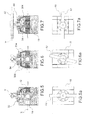
- This command element 40 can be rotated between a first position, in which both the valve obturator 18 and the bypass obturator 32 are in the closed position ( figures 2 and 5 ), and a second position, in which the valve obturator 18 is in the open position and the bypass obturator 32 is in the closed position figures 4 and 7 ), passing through an intermediate position, in which the valve obturator 18 is still in the closed position while the bypass obturator 32 is in the open position ( figures 3 and 6 ).
- the command element 40 causes the rotation of the bypass obturator 32 only.
- the command element 40 causes the rotation both of the valve obturator 18 and of the bypass obturator 32. It should be noted that, as shown in figures 4, 4a and 7 , upon reaching the second position the bypass duct 30 is closed again and the valve works normally in its open configuration.
- command element 40 is integral in rotation with the bypass obturator 32 and engages the valve obturator 18 angularly only upon reaching the intermediate position.
- the bypass duct 30 has a through cross-section of the fluid smaller than the through cross-section of the inlet duct 12. Therefore, the first phase of rotation of the command element 40, which concerns only the bypass obturator 32, requires a torque on the command element 40 significantly lower than the torque needed to rotate the valve obturator 18.
- the command element 40 comprises a rotatable command device 42, such as a lever, and a command shaft 44 which transmits the rotation of said command device to the valve obturator 18.
- the bypass obturator 32 is made in said command shaft 42.
- the command shaft 44 and bypass obturator 32 are made integrally in a single body.
- the command shaft 44 has a (lower) end portion 442 having a substantially rectangular cross section housed in a shaft seat 184 made in the valve obturator 18. Said end portion 442 is free to rotate in said shaft seat 184 by an angle equal to the shift from the first position to the intermediate position.
- the shaft seat 184 consists of a recess made in the valve obturator 18 and delimited by inclined walls.
- the command shaft 44 is housed in a shaft seat 444 made in the valve body 10.
- Said shaft seat 444 delimits an intermediate portion 302 of the bypass duct 30.
- Said intermediate portion 302 of the bypass duct houses the bypass obturator 32.
- said intermediate portion 302 of the bypass duct 30 extends in a direction substantially orthogonal to the rotation axis Y of the command shaft 44.
- said intermediate portion 302 of the bypass duct 30 communicates fluidically with an inlet portion 304 of the bypass duct 30 made in the valve body 10 and with an outlet portion 306 of the bypass duct 30, made in the valve body 10.
- bypass obturator 32 interfaces with said inlet 304 and outlet 306 portions of the bypass duct 30 by means of bypass gaskets 308. It is to be noted that the contact surface of said bypass gaskets 308 with the bypass obturator 32 is considerably smaller than the contact surface of the gaskets of the valve obturator 20. The sticking effect between the bypass gaskets 308 and the bypass obturator 32 is thus considerably reduced compared to that generated between the valve obturator 18 and relative gaskets 20.
- the command shaft 44 comprises a lower portion 442 coupling to the valve obturator 18, an upper portion 446 coupling to the command device 42, and an intermediate portion which forms the bypass obturator 32 and which is housed in said intermediate portion 302 of the bypass duct 30.
- a transversal bypass passage 34 is made in the bypass obturator 32.
- the bypass obturator 32 is disc-shaped with its rotation axis coinciding with the rotation axis Y of the command element. Such disc shape facilitates the guided rotation of the command element, which the bypass obturator is part of, and at the same time enables a limitation of the dimensions of the valve in height.
- the bypass passage 34 is aligned with the inlet 304 and outlet 306 portions of the bypass duct 30, and the latter is thus opened ( figure 3a ).
- the valve obturator 18 is still in its starting position of valve closed. The pressure of the fluid acting on the valve obturator can be released downstream of the valve obturator, as shown in figure 6 , through the bypass duct 30.
- bypass duct has exhausted its task and the valve obturator 18 can be rotated with a significantly lower torque than would be needed in the presence of pressure in the inlet duct 12 only.
- command element 40 causes the rotation both of the valve obturator 18 and of the bypass obturator 32.
- valve obturator 18 At the end of the rotation, for example equal to 90°, of the command element 40 ( figures 4 , 7, 7a ), the valve obturator 18 is in the open position of the main passage, while the bypass passage 442 is offset again (substantially orthogonal) to the inlet 304 and outlet 306 portions of the bypass duct 30.
- figures 8 and 8a illustrate the application of the technical solution of the present invention to a "guided" ball intercepting valve 100 i.e. a valve where the ball obturator 180 is engaged, as well as by the command shaft 44, by a counter-shaft 440 aligned and opposite the command shaft.
- Shaft 44 and counter-shaft 440 ensure the continued alignment of the centre of the ball obturator 180 with the rotation axis Y of the command shaft. Consequently, the only movement that the ball obturator is able to perform is the rotation around the rotation axis Y.
- the seal on the ball obturator 180 is guaranteed for each of the inlet and outlet ducts, by a sealing ring 200, for example made of plastic, housed in a respective annular shape ring seat 202.
- the assembly of the sealing ring 200 and of the relative seat 202 is mounted between the ball obturator and the valve body 10 with the possibility of axial translation along the main axis X.
- an elastic means 204 for example a plurality of springs housed in respective spring seats made in the valve body 10, act, suitable to keep the sealing ring 200 pressed against the surface of the ball obturator 180.
- the presence of the elastic means 204 acting on the sealing assembly ensures the seal even in the presence of a low fluid pressure acting on the ball obturator.
- bypass circuit described above facilitates the actuation of the command shaft 44 to rotate the ball obturator 180, even in the case of valves with a particularly large through diameter.
Landscapes
- Engineering & Computer Science (AREA)
- General Engineering & Computer Science (AREA)
- Mechanical Engineering (AREA)
- Taps Or Cocks (AREA)
- Multiple-Way Valves (AREA)
- Fluid-Driven Valves (AREA)
Applications Claiming Priority (1)
| Application Number | Priority Date | Filing Date | Title |
|---|---|---|---|
| IT000182A ITBS20130182A1 (it) | 2013-12-16 | 2013-12-16 | Valvola di intercettazione di un fluido |
Publications (2)
| Publication Number | Publication Date |
|---|---|
| EP2884144A1 true EP2884144A1 (fr) | 2015-06-17 |
| EP2884144B1 EP2884144B1 (fr) | 2017-01-04 |
Family
ID=50115965
Family Applications (1)
| Application Number | Title | Priority Date | Filing Date |
|---|---|---|---|
| EP14198304.9A Not-in-force EP2884144B1 (fr) | 2013-12-16 | 2014-12-16 | Valve |
Country Status (4)
| Country | Link |
|---|---|
| EP (1) | EP2884144B1 (fr) |
| DK (1) | DK2884144T3 (fr) |
| ES (1) | ES2620973T3 (fr) |
| IT (1) | ITBS20130182A1 (fr) |
Citations (2)
| Publication number | Priority date | Publication date | Assignee | Title |
|---|---|---|---|---|
| BE498186A (fr) * | ||||
| FR857607A (fr) * | 1939-07-10 | 1940-09-21 | Vanne équilibrée pivotante |
-
2013
- 2013-12-16 IT IT000182A patent/ITBS20130182A1/it unknown
-
2014
- 2014-12-16 EP EP14198304.9A patent/EP2884144B1/fr not_active Not-in-force
- 2014-12-16 DK DK14198304.9T patent/DK2884144T3/en active
- 2014-12-16 ES ES14198304.9T patent/ES2620973T3/es active Active
Patent Citations (2)
| Publication number | Priority date | Publication date | Assignee | Title |
|---|---|---|---|---|
| BE498186A (fr) * | ||||
| FR857607A (fr) * | 1939-07-10 | 1940-09-21 | Vanne équilibrée pivotante |
Also Published As
| Publication number | Publication date |
|---|---|
| EP2884144B1 (fr) | 2017-01-04 |
| ITBS20130182A1 (it) | 2015-06-17 |
| ES2620973T3 (es) | 2017-06-30 |
| DK2884144T3 (en) | 2017-03-27 |
Similar Documents
| Publication | Publication Date | Title |
|---|---|---|
| EP3295067B1 (fr) | Robinet à bille avec élément limiteur de pression | |
| CN102292582B (zh) | 具有失控设备的致动器 | |
| EP2519752B1 (fr) | Appareil pour augmenter la force d'un actionneur comportant un dispositif de neutralisation | |
| JPH10504875A (ja) | 減衰器およびダイナミックシールを有する流体制御弁 | |
| KR102375630B1 (ko) | 로크아웃 표지 장치 및 밸브 | |
| US9297461B2 (en) | Block and bleed valve assembly | |
| KR102166939B1 (ko) | 멀티 포트 밸브 | |
| US20190107214A1 (en) | Manifolds for pressure relief systems | |
| CN107366750B (zh) | 一种制冷系统用截止阀 | |
| US10550945B2 (en) | Emergency shutdown valves with bypass features | |
| KR20180029714A (ko) | 직각 밸브 | |
| WO2015157228A1 (fr) | Régulation de fluide à bouchage et écoulement | |
| EP2884144B1 (fr) | Valve | |
| US20160319941A1 (en) | Ball valve assembly | |
| US9970553B2 (en) | Pressure balancing gate valve | |
| US20120180888A1 (en) | High flow service valve | |
| ZA200501106B (en) | Valve, in particular steam valve | |
| US20100147388A1 (en) | Directional gate valve | |
| CN109404567B (zh) | 一种三通电磁阀 | |
| EP3260750B1 (fr) | Ensemble de soupape ayant une unité de commande prioritaire manuelle | |
| CN211117837U (zh) | 流体控制设备和紧急关断阀 | |
| JP2024528749A (ja) | 安全弁 | |
| KR100775014B1 (ko) | 유로 전환이 가능한 밸브 | |
| US20200182378A1 (en) | Retention mechanism for noise attenuation dome in fluid flow control device | |
| CN121701677A (zh) | 一种阀装置 |
Legal Events
| Date | Code | Title | Description |
|---|---|---|---|
| PUAI | Public reference made under article 153(3) epc to a published international application that has entered the european phase |
Free format text: ORIGINAL CODE: 0009012 |
|
| 17P | Request for examination filed |
Effective date: 20141216 |
|
| AK | Designated contracting states |
Kind code of ref document: A1 Designated state(s): AL AT BE BG CH CY CZ DE DK EE ES FI FR GB GR HR HU IE IS IT LI LT LU LV MC MK MT NL NO PL PT RO RS SE SI SK SM TR |
|
| AX | Request for extension of the european patent |
Extension state: BA ME |
|
| R17P | Request for examination filed (corrected) |
Effective date: 20151215 |
|
| RBV | Designated contracting states (corrected) |
Designated state(s): AL AT BE BG CH CY CZ DE DK EE ES FI FR GB GR HR HU IE IS IT LI LT LU LV MC MK MT NL NO PL PT RO RS SE SI SK SM TR |
|
| 17Q | First examination report despatched |
Effective date: 20160114 |
|
| GRAP | Despatch of communication of intention to grant a patent |
Free format text: ORIGINAL CODE: EPIDOSNIGR1 |
|
| INTG | Intention to grant announced |
Effective date: 20160725 |
|
| GRAS | Grant fee paid |
Free format text: ORIGINAL CODE: EPIDOSNIGR3 |
|
| GRAA | (expected) grant |
Free format text: ORIGINAL CODE: 0009210 |
|
| AK | Designated contracting states |
Kind code of ref document: B1 Designated state(s): AL AT BE BG CH CY CZ DE DK EE ES FI FR GB GR HR HU IE IS IT LI LT LU LV MC MK MT NL NO PL PT RO RS SE SI SK SM TR |
|
| REG | Reference to a national code |
Ref country code: GB Ref legal event code: FG4D |
|
| REG | Reference to a national code |
Ref country code: CH Ref legal event code: EP |
|
| REG | Reference to a national code |
Ref country code: AT Ref legal event code: REF Ref document number: 859585 Country of ref document: AT Kind code of ref document: T Effective date: 20170115 |
|
| REG | Reference to a national code |
Ref country code: IE Ref legal event code: FG4D |
|
| REG | Reference to a national code |
Ref country code: DE Ref legal event code: R096 Ref document number: 602014006018 Country of ref document: DE |
|
| REG | Reference to a national code |
Ref country code: DK Ref legal event code: T3 Effective date: 20170321 |
|
| REG | Reference to a national code |
Ref country code: SE Ref legal event code: TRGR |
|
| REG | Reference to a national code |
Ref country code: CH Ref legal event code: NV Representative=s name: JACOBACCI AND PARTNERS SA, CH |
|
| REG | Reference to a national code |
Ref country code: NL Ref legal event code: FP |
|
| REG | Reference to a national code |
Ref country code: NO Ref legal event code: T2 Effective date: 20170104 |
|
| REG | Reference to a national code |
Ref country code: LT Ref legal event code: MG4D |
|
| REG | Reference to a national code |
Ref country code: ES Ref legal event code: FG2A Ref document number: 2620973 Country of ref document: ES Kind code of ref document: T3 Effective date: 20170630 |
|
| PG25 | Lapsed in a contracting state [announced via postgrant information from national office to epo] |
Ref country code: GR Free format text: LAPSE BECAUSE OF FAILURE TO SUBMIT A TRANSLATION OF THE DESCRIPTION OR TO PAY THE FEE WITHIN THE PRESCRIBED TIME-LIMIT Effective date: 20170405 Ref country code: FI Free format text: LAPSE BECAUSE OF FAILURE TO SUBMIT A TRANSLATION OF THE DESCRIPTION OR TO PAY THE FEE WITHIN THE PRESCRIBED TIME-LIMIT Effective date: 20170104 Ref country code: LT Free format text: LAPSE BECAUSE OF FAILURE TO SUBMIT A TRANSLATION OF THE DESCRIPTION OR TO PAY THE FEE WITHIN THE PRESCRIBED TIME-LIMIT Effective date: 20170104 Ref country code: HR Free format text: LAPSE BECAUSE OF FAILURE TO SUBMIT A TRANSLATION OF THE DESCRIPTION OR TO PAY THE FEE WITHIN THE PRESCRIBED TIME-LIMIT Effective date: 20170104 Ref country code: IS Free format text: LAPSE BECAUSE OF FAILURE TO SUBMIT A TRANSLATION OF THE DESCRIPTION OR TO PAY THE FEE WITHIN THE PRESCRIBED TIME-LIMIT Effective date: 20170504 |
|
| PG25 | Lapsed in a contracting state [announced via postgrant information from national office to epo] |
Ref country code: BG Free format text: LAPSE BECAUSE OF FAILURE TO SUBMIT A TRANSLATION OF THE DESCRIPTION OR TO PAY THE FEE WITHIN THE PRESCRIBED TIME-LIMIT Effective date: 20170404 Ref country code: LV Free format text: LAPSE BECAUSE OF FAILURE TO SUBMIT A TRANSLATION OF THE DESCRIPTION OR TO PAY THE FEE WITHIN THE PRESCRIBED TIME-LIMIT Effective date: 20170104 Ref country code: PT Free format text: LAPSE BECAUSE OF FAILURE TO SUBMIT A TRANSLATION OF THE DESCRIPTION OR TO PAY THE FEE WITHIN THE PRESCRIBED TIME-LIMIT Effective date: 20170504 Ref country code: RS Free format text: LAPSE BECAUSE OF FAILURE TO SUBMIT A TRANSLATION OF THE DESCRIPTION OR TO PAY THE FEE WITHIN THE PRESCRIBED TIME-LIMIT Effective date: 20170104 Ref country code: PL Free format text: LAPSE BECAUSE OF FAILURE TO SUBMIT A TRANSLATION OF THE DESCRIPTION OR TO PAY THE FEE WITHIN THE PRESCRIBED TIME-LIMIT Effective date: 20170104 |
|
| REG | Reference to a national code |
Ref country code: DE Ref legal event code: R097 Ref document number: 602014006018 Country of ref document: DE |
|
| PG25 | Lapsed in a contracting state [announced via postgrant information from national office to epo] |
Ref country code: CZ Free format text: LAPSE BECAUSE OF FAILURE TO SUBMIT A TRANSLATION OF THE DESCRIPTION OR TO PAY THE FEE WITHIN THE PRESCRIBED TIME-LIMIT Effective date: 20170104 Ref country code: SK Free format text: LAPSE BECAUSE OF FAILURE TO SUBMIT A TRANSLATION OF THE DESCRIPTION OR TO PAY THE FEE WITHIN THE PRESCRIBED TIME-LIMIT Effective date: 20170104 Ref country code: RO Free format text: LAPSE BECAUSE OF FAILURE TO SUBMIT A TRANSLATION OF THE DESCRIPTION OR TO PAY THE FEE WITHIN THE PRESCRIBED TIME-LIMIT Effective date: 20170104 Ref country code: IT Free format text: LAPSE BECAUSE OF FAILURE TO SUBMIT A TRANSLATION OF THE DESCRIPTION OR TO PAY THE FEE WITHIN THE PRESCRIBED TIME-LIMIT Effective date: 20170104 Ref country code: EE Free format text: LAPSE BECAUSE OF FAILURE TO SUBMIT A TRANSLATION OF THE DESCRIPTION OR TO PAY THE FEE WITHIN THE PRESCRIBED TIME-LIMIT Effective date: 20170104 |
|
| PLBE | No opposition filed within time limit |
Free format text: ORIGINAL CODE: 0009261 |
|
| STAA | Information on the status of an ep patent application or granted ep patent |
Free format text: STATUS: NO OPPOSITION FILED WITHIN TIME LIMIT |
|
| PG25 | Lapsed in a contracting state [announced via postgrant information from national office to epo] |
Ref country code: SM Free format text: LAPSE BECAUSE OF FAILURE TO SUBMIT A TRANSLATION OF THE DESCRIPTION OR TO PAY THE FEE WITHIN THE PRESCRIBED TIME-LIMIT Effective date: 20170104 |
|
| REG | Reference to a national code |
Ref country code: FR Ref legal event code: PLFP Year of fee payment: 4 |
|
| PG25 | Lapsed in a contracting state [announced via postgrant information from national office to epo] |
Ref country code: SI Free format text: LAPSE BECAUSE OF FAILURE TO SUBMIT A TRANSLATION OF THE DESCRIPTION OR TO PAY THE FEE WITHIN THE PRESCRIBED TIME-LIMIT Effective date: 20170104 |
|
| REG | Reference to a national code |
Ref country code: IE Ref legal event code: MM4A |
|
| PG25 | Lapsed in a contracting state [announced via postgrant information from national office to epo] |
Ref country code: MT Free format text: LAPSE BECAUSE OF NON-PAYMENT OF DUE FEES Effective date: 20171216 |
|
| REG | Reference to a national code |
Ref country code: BE Ref legal event code: MM Effective date: 20171231 |
|
| PG25 | Lapsed in a contracting state [announced via postgrant information from national office to epo] |
Ref country code: IE Free format text: LAPSE BECAUSE OF NON-PAYMENT OF DUE FEES Effective date: 20171216 |
|
| PG25 | Lapsed in a contracting state [announced via postgrant information from national office to epo] |
Ref country code: BE Free format text: LAPSE BECAUSE OF NON-PAYMENT OF DUE FEES Effective date: 20171231 |
|
| PG25 | Lapsed in a contracting state [announced via postgrant information from national office to epo] |
Ref country code: MC Free format text: LAPSE BECAUSE OF FAILURE TO SUBMIT A TRANSLATION OF THE DESCRIPTION OR TO PAY THE FEE WITHIN THE PRESCRIBED TIME-LIMIT Effective date: 20170104 Ref country code: HU Free format text: LAPSE BECAUSE OF FAILURE TO SUBMIT A TRANSLATION OF THE DESCRIPTION OR TO PAY THE FEE WITHIN THE PRESCRIBED TIME-LIMIT; INVALID AB INITIO Effective date: 20141216 |
|
| REG | Reference to a national code |
Ref country code: AT Ref legal event code: UEP Ref document number: 859585 Country of ref document: AT Kind code of ref document: T Effective date: 20170104 |
|
| PG25 | Lapsed in a contracting state [announced via postgrant information from national office to epo] |
Ref country code: CY Free format text: LAPSE BECAUSE OF FAILURE TO SUBMIT A TRANSLATION OF THE DESCRIPTION OR TO PAY THE FEE WITHIN THE PRESCRIBED TIME-LIMIT Effective date: 20170104 |
|
| PG25 | Lapsed in a contracting state [announced via postgrant information from national office to epo] |
Ref country code: MK Free format text: LAPSE BECAUSE OF FAILURE TO SUBMIT A TRANSLATION OF THE DESCRIPTION OR TO PAY THE FEE WITHIN THE PRESCRIBED TIME-LIMIT Effective date: 20170104 |
|
| PG25 | Lapsed in a contracting state [announced via postgrant information from national office to epo] |
Ref country code: TR Free format text: LAPSE BECAUSE OF FAILURE TO SUBMIT A TRANSLATION OF THE DESCRIPTION OR TO PAY THE FEE WITHIN THE PRESCRIBED TIME-LIMIT Effective date: 20170104 |
|
| PG25 | Lapsed in a contracting state [announced via postgrant information from national office to epo] |
Ref country code: AL Free format text: LAPSE BECAUSE OF FAILURE TO SUBMIT A TRANSLATION OF THE DESCRIPTION OR TO PAY THE FEE WITHIN THE PRESCRIBED TIME-LIMIT Effective date: 20170104 |
|
| PGFP | Annual fee paid to national office [announced via postgrant information from national office to epo] |
Ref country code: FR Payment date: 20201228 Year of fee payment: 7 Ref country code: NO Payment date: 20201222 Year of fee payment: 7 Ref country code: AT Payment date: 20201218 Year of fee payment: 7 Ref country code: DK Payment date: 20201223 Year of fee payment: 7 Ref country code: SE Payment date: 20201216 Year of fee payment: 7 Ref country code: CH Payment date: 20201221 Year of fee payment: 7 Ref country code: GB Payment date: 20201223 Year of fee payment: 7 |
|
| PGFP | Annual fee paid to national office [announced via postgrant information from national office to epo] |
Ref country code: LU Payment date: 20201223 Year of fee payment: 7 Ref country code: NL Payment date: 20201229 Year of fee payment: 7 |
|
| PGFP | Annual fee paid to national office [announced via postgrant information from national office to epo] |
Ref country code: ES Payment date: 20210105 Year of fee payment: 7 Ref country code: DE Payment date: 20201229 Year of fee payment: 7 |
|
| REG | Reference to a national code |
Ref country code: DE Ref legal event code: R119 Ref document number: 602014006018 Country of ref document: DE |
|
| REG | Reference to a national code |
Ref country code: NO Ref legal event code: MMEP Ref country code: DK Ref legal event code: EBP Effective date: 20211231 |
|
| REG | Reference to a national code |
Ref country code: CH Ref legal event code: PL |
|
| REG | Reference to a national code |
Ref country code: SE Ref legal event code: EUG |
|
| REG | Reference to a national code |
Ref country code: NL Ref legal event code: MM Effective date: 20220101 |
|
| REG | Reference to a national code |
Ref country code: AT Ref legal event code: MM01 Ref document number: 859585 Country of ref document: AT Kind code of ref document: T Effective date: 20211216 |
|
| GBPC | Gb: european patent ceased through non-payment of renewal fee |
Effective date: 20211216 |
|
| PG25 | Lapsed in a contracting state [announced via postgrant information from national office to epo] |
Ref country code: NL Free format text: LAPSE BECAUSE OF NON-PAYMENT OF DUE FEES Effective date: 20220101 |
|
| PG25 | Lapsed in a contracting state [announced via postgrant information from national office to epo] |
Ref country code: SE Free format text: LAPSE BECAUSE OF NON-PAYMENT OF DUE FEES Effective date: 20211217 Ref country code: NO Free format text: LAPSE BECAUSE OF NON-PAYMENT OF DUE FEES Effective date: 20211231 Ref country code: LU Free format text: LAPSE BECAUSE OF NON-PAYMENT OF DUE FEES Effective date: 20211216 Ref country code: GB Free format text: LAPSE BECAUSE OF NON-PAYMENT OF DUE FEES Effective date: 20211216 Ref country code: DE Free format text: LAPSE BECAUSE OF NON-PAYMENT OF DUE FEES Effective date: 20220701 Ref country code: AT Free format text: LAPSE BECAUSE OF NON-PAYMENT OF DUE FEES Effective date: 20211216 |
|
| PG25 | Lapsed in a contracting state [announced via postgrant information from national office to epo] |
Ref country code: FR Free format text: LAPSE BECAUSE OF NON-PAYMENT OF DUE FEES Effective date: 20211231 |
|
| PG25 | Lapsed in a contracting state [announced via postgrant information from national office to epo] |
Ref country code: LI Free format text: LAPSE BECAUSE OF NON-PAYMENT OF DUE FEES Effective date: 20211231 Ref country code: CH Free format text: LAPSE BECAUSE OF NON-PAYMENT OF DUE FEES Effective date: 20211231 |
|
| PG25 | Lapsed in a contracting state [announced via postgrant information from national office to epo] |
Ref country code: DK Free format text: LAPSE BECAUSE OF NON-PAYMENT OF DUE FEES Effective date: 20211231 |
|
| REG | Reference to a national code |
Ref country code: ES Ref legal event code: FD2A Effective date: 20230301 |
|
| PG25 | Lapsed in a contracting state [announced via postgrant information from national office to epo] |
Ref country code: ES Free format text: LAPSE BECAUSE OF NON-PAYMENT OF DUE FEES Effective date: 20211217 |