EP2884183A1 - Bündelrohrkraftstoffinjektor - Google Patents
Bündelrohrkraftstoffinjektor Download PDFInfo
- Publication number
- EP2884183A1 EP2884183A1 EP14197247.1A EP14197247A EP2884183A1 EP 2884183 A1 EP2884183 A1 EP 2884183A1 EP 14197247 A EP14197247 A EP 14197247A EP 2884183 A1 EP2884183 A1 EP 2884183A1
- Authority
- EP
- European Patent Office
- Prior art keywords
- tube
- mix
- fuel injector
- bundled
- tip
- Prior art date
- Legal status (The legal status is an assumption and is not a legal conclusion. Google has not performed a legal analysis and makes no representation as to the accuracy of the status listed.)
- Granted
Links
Images


Classifications
-
- F—MECHANICAL ENGINEERING; LIGHTING; HEATING; WEAPONS; BLASTING
- F23—COMBUSTION APPARATUS; COMBUSTION PROCESSES
- F23R—GENERATING COMBUSTION PRODUCTS OF HIGH PRESSURE OR HIGH VELOCITY, e.g. GAS-TURBINE COMBUSTION CHAMBERS
- F23R3/00—Continuous combustion chambers using liquid or gaseous fuel
- F23R3/28—Continuous combustion chambers using liquid or gaseous fuel characterised by the fuel supply
- F23R3/283—Attaching or cooling of fuel injecting means including supports for fuel injectors, stems, or lances
-
- F—MECHANICAL ENGINEERING; LIGHTING; HEATING; WEAPONS; BLASTING
- F23—COMBUSTION APPARATUS; COMBUSTION PROCESSES
- F23R—GENERATING COMBUSTION PRODUCTS OF HIGH PRESSURE OR HIGH VELOCITY, e.g. GAS-TURBINE COMBUSTION CHAMBERS
- F23R3/00—Continuous combustion chambers using liquid or gaseous fuel
- F23R3/28—Continuous combustion chambers using liquid or gaseous fuel characterised by the fuel supply
- F23R3/286—Continuous combustion chambers using liquid or gaseous fuel characterised by the fuel supply having fuel-air premixing devices
Definitions
- the present invention generally involves a bundled tube fuel injector such as may be incorporated into a combustor of a gas turbine or other turbomachine. Specifically, the invention relates to a tube tip for pre-mix tubes of the bundled tube fuel injector.
- a typical gas turbine may include a compressor section, a combustion section disposed downstream from the compressor section, and a turbine section disposed downstream from the combustion section.
- a working fluid such as ambient air flows into the compressor section where it is progressively compressed before flowing into the combustion section.
- the compressed working fluid is mixed with a fuel and burned within one or more combustors of the combustion section to generate combustion gases having a high temperature, pressure, and velocity.
- the combustion gases flow from the combustors and expand through the turbine section to produce thrust and/or to rotate a shaft, thus producing work.
- the combustors may be annularly arranged between the compressor section and the turbine section.
- the combustors include one or more axially extending bundled tube fuel injectors that extend downstream from an end cover.
- the bundled tube fuel injector generally includes a plurality of pre-mix tubes arranged radially and circumferentially across the bundled tube fuel injector.
- the pre-mix tubes extend generally parallel to one another.
- An outer shroud extends circumferentially around the pre-mix tubes downstream from a fuel distribution module of the bundled tube fuel injector.
- An aft plate extends radially and circumferentially across a downstream end of the outer shroud adjacent to a combustion chamber or zone defined within the combustor.
- a cooling air or purge air plenum is at least partially defined within the outer shroud between the fuel distribution manifold and the aft plate.
- each pre-mix tube extends through the aft plate such that an outlet of each tube is downstream from a hot side surface of the aft plate, thus providing for fluid communication into the combustion chamber or zone.
- Each of the pre-mix tubes extends generally axially through the fuel distribution module and the cooling air plenum.
- the compressed working fluid is routed through inlets of each of the parallel pre-mix tubes upstream from the fuel distribution module.
- Fuel is supplied to the fuel plenum through the fluid conduit and the fuel is injected into the pre-mix tubes through one or more fuel ports defined within each of the pre-mix tubes.
- the fuel and compressed working fluid mix inside the pre-mix tubes before flowing out of the outlet which is defined at the downstream or end portion of each of the pre-mix tubes and into the combustion chamber or zone for combustion.
- the downstream or end portion of the pre-mix tubes is exposed to extreme temperatures due their proximity to the combustion chamber and/or the combustion flame. Over time, the downstream or end portion of the pre-mix tubes degrades due to the thermal stresses, thus requiring scheduled inspection and in some cases repair or refurbishment of the bundled tube fuel injectors. Materials that are suitable for high or extreme temperatures and that may enhance the life of the pre-mix tubes are relatively expensive. As a result it may be impractical and/or cost prohibitive to manufacture the pre-mix tubes entirely from these materials. Therefore, an improved bundled tube fuel injector would be useful.
- the bundled tube fuel injector includes a fuel plenum that is defined within the bundled tube fuel injector and a plurality of pre-mix tubes that extend downstream from the fuel plenum substantially parallel to one another.
- Each pre-mix tube includes an end portion and a radially extending end surface.
- the bundled tube fuel injector further includes a tube tip that is fixedly connected to the end portion of a corresponding pre-mix tube.
- a combustor having an outer casing, an end cover coupled to the outer casing and a bundled tube fuel injector coupled to the end cover and extending axially downstream from the end cover.
- the bundled tube fuel injector comprises a fuel plenum that is defined within the bundled tube fuel injector and a plurality of pre-mix tubes that extend downstream from the fuel plenum substantially parallel to one another.
- Each pre-mix tube includes an end portion and a radially extending end surface.
- the bundled tube fuel injector further includes a tube tip that is fixedly connected to the end portion of a corresponding pre-mix tube.
- the combustor may be coupled to a turbomachine such as a gas turbine.
- upstream refers to the direction from which the fluid flows
- downstream refers to the direction to which the fluid flows.
- radially refers to the relative direction that is substantially perpendicular to an axial centerline of a particular component
- axially refers to the relative direction that is substantially parallel to an axial centerline of a particular component.
- FIG. 1 provides a functional block diagram of an exemplary gas turbine 10 that may incorporate various embodiments of the present invention.
- the gas turbine 10 generally includes an inlet section 12 that may include a series of filters, cooling coils, moisture separators, and/or other devices to purify and otherwise condition a working fluid (e.g., air) 14 entering the gas turbine 10.
- the working fluid 14 flows to a compressor section where a compressor 16 progressively imparts kinetic energy to the working fluid 14 to produce a compressed working fluid 18.
- the compressed working fluid 18 is mixed with a fuel 20 from a fuel source 22 such as a fuel skid to form a combustible mixture within one or more combustors 24.
- the combustible mixture is burned to produce combustion gases 26 having a high temperature, pressure and velocity.
- the combustion gases 26 flow through a turbine 28 of a turbine section to produce work.
- the turbine 28 may be connected to a shaft 30 so that rotation of the turbine 28 drives the compressor 16 to produce the compressed working fluid 18.
- the shaft 30 may connect the turbine 28 to a generator 32 for producing electricity.
- Exhaust gases 34 from the turbine 28 flow through an exhaust section 36 that connects the turbine 28 to an exhaust stack 38 downstream from the turbine 28.
- the exhaust section 36 may include, for example, a heat recovery steam generator (not shown) for cleaning and extracting additional heat from the exhaust gases 34 prior to release to the environment.
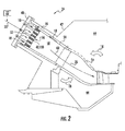
- FIG. 2 provides a simplified cross section of an exemplary combustor 24 as may incorporate a bundled tube fuel injector 40 configured according to at least one embodiment of the present disclosure.
- the combustor 24 is at least partially surrounded by an outer casing 42.
- the outer casing 42 at least partially forms a high pressure plenum 44 around the combustor 24.
- the high pressure plenum 44 may be in fluid communication with the compressor 16 or other source for supplying the compressed working fluid 18 to the combustor 24.
- an end cover 48 is coupled to the outer casing 42.
- the end cover 48 may be in fluid communication with the fuel supply 22.
- the bundled tube fuel injector 40 extends downstream from the end cover 48.
- the bundled tube fuel injector 40 may be fluidly connected to the end cover 48 so as to receive fuel from the fuel supply 22.
- a fluid conduit 52 may provide for fluid communication between the end cover 48 and/or the fuel supply 22 and the bundled tube fuel injector 40.
- One end of an annular liner 54 such as a combustion liner and/or a transition duct surrounds a downstream end 56 of the bundled tube fuel injector 40 so as to at least partially define a combustion chamber 58 within the combustor 24.
- the liner 54 at least partially defines a hot gas path 60 for directing the combustion gases 26 from the combustion chamber 58 through the combustor 24.
- the hot gas path 60 may be configured to route the combustion gases 26 towards the turbine 28 and/or the exhaust section.
- the compressed working fluid 18 is routed towards the end cover 48 where it reverses direction and flows through one or more of the bundled tube fuel injectors 40.
- the fuel 20 is provided to the bundled tube fuel injector 40 and the fuel 20 and the compressed working fluid 18 are premixed or combined within the bundled tube fuel injector 40 before being injected into a combustion chamber 58 for combustion.
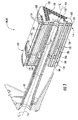
- FIG. 3 is a cross section perspective view of an exemplary bundled tube fuel injector 100 herein referred to as "fuel injector” as may be incorporated into the combustor 24 as described in FIG. 2 , according to various embodiments of the present disclosure.
- the fuel injector 100 generally includes a fuel distribution module 102 that is in fluid communication with the fluid conduit 52.
- the fuel distribution module 102 includes an upstream plate 104 that is axially separated from a downstream plate 106.
- the upstream and downstream plates 104, 106 extend generally radially and circumferentially within the fuel injector 100.
- An outer band 108 circumferentially surrounds and extends axially between the upstream and downstream plates 104, 106.
- the outer band 108 may extend axially beyond either one or both of the upstream and downstream plates 104, 106.
- a fuel plenum 110 may be at least partially defined between the upstream and downstream plates 104, 106 and the outer band 108.
- the fluid conduit 52 provides for fluid communication between the fuel supply 22 ( FIG. 1 ) and the fuel plenum 110.
- an aft plate 112 is disposed at a downstream or aft end 114 of the fuel injector 100.
- the aft plate 112 extends radially outwardly and circumferentially across the aft end 114 with respect an axial centerline 116 of the fuel injector 100.
- the aft plate 112 at least partially defines a plurality of tube tip passages 118 that extend generally axially through the aft plate 112.
- an impingement plate 120 is disposed upstream from the aft plate 112.
- the impingement plate 120 may be welded, brazed or otherwise coupled to the aft plate 112.
- the aft plate 112 and/or the impingement plate 120 may at least partially define a cartridge or fuel nozzle passage 122 that extends generally axially therethrough.
- a fluid cartridge or fuel nozzle 124 may be coupled to the aft plate 112 at the center nozzle passage 122.
- An outer shroud 126 may extend generally axially between the fuel distribution module 102 and the aft plate 112.
- the outer shroud 126 may be coupled to the aft plate 112 and/or the fuel distribution module 102 via welding, brazing, mechanical fasteners or by any suitable means for the operating environment of the fuel injector 100.
- the fuel injector 100 includes a pre-mix tube bundle 128.
- the pre-mix tube bundle 128 comprises a plurality of pre-mix tubes 130 that extend generally parallel to one another along or parallel to the axial centerline 116 of the fuel injector 100.
- the pre-mix tubes 130 extend downstream from the fuel plenum 110 towards the aft plate 112 and/or the combustion chamber 58 ( FIG. 2 ). A portion of the pre-mix tubes 130 extends through the fuel plenum 110.
- the pre-mix tubes 130 may be formed from a single continuous tube or may be formed from two or more coaxially aligned tubes fixedly joined together. Although generally illustrated as cylindrical, the pre-mix tubes 130 may be any geometric shape, and the present invention is not limited to any particular cross-section unless specifically recited in the claims. In addition, the pre-mix tubes 130 may be grouped or arranged in circular, triangular, square, or other geometric shapes, and may be arranged in various numbers and geometries.
- each pre-mix tube 130 is generally aligned with a corresponding tube tip passage 118.
- the pre-mix tubes 130 are arranged in multiple rows 132.
- Each row 132 may include one or more of the pre-mix tubes 130.
- each row 132 is radially spaced with respect to the axial centerline 116 from an adjacent row 132.
- the pre-mix tubes 130 of at least some of the rows 132 may be arranged annularly around the axial centerline 116.
- the pre-mix tubes 130 of each row 132 may be arranged generally circumferentially across the fuel injector 100 with respect to an axial centerline of the combustor 24 and/or the axial centerline 116 of the fuel injector 100.
- An exemplary pre-mix tube 130 generally includes an inlet 134 defined upstream from the fuel plenum 110 and/or the upstream plate 104.
- the inlet 134 may be in fluid communication with the high pressure plenum 44 and/or the compressor 16.
- a downstream or end portion 136 is defined downstream from the fuel plenum 110.
- a radially extending surface 138 is defined between an inner and outer diameter of the pre-mix tube 130 at a distal end of the end portion 136.
- One or more fuel ports 140 may provide for fluid communication between the fuel plenum 110 and a corresponding pre-mix passage 142 within the pre-mix tubes 130.
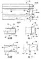
- FIG. 4 is an enlarged cross sectional side view of a portion of the fuel injector 100 as shown in FIG. 3 , according to various embodiments of the present disclosure.
- a tube tip 200 is fixedly connected to the end portion 136 of a corresponding pre-mix tube 130.
- the tube tip 200 may comprise high temperature alloys that are dissimilar to a material that forms the corresponding pre-mix tube.
- the tube tip 200 may comprise of at least one of nickel, cobalt, chromium, molybdenum or stainless steel based alloys.
- the fuel injector 100 may include a plurality of tube tips 200 in one or more configurations, as described below, each coupled to a corresponding end portion 136 of a corresponding pre-mix tube 130.
- an exemplary tube tip 210 comprises a mating end 212, an opposing outlet end 214 and a pre-mix portion 216 that extends therebetween.
- the outlet end 214 extends axially through a corresponding tube tip passage 118 of the aft plate 112.
- the mating end 212 of the tube tip 210 defines a socket 218.
- the socket 218 is configured to receive a portion of the end portion 136 of the corresponding pre-mix tube 130.
- the socket 218 generally has an inner diameter that is greater than an outer diameter of the end portion 136 of the pre-mix tube 130.
- the socket 218 also extends axially across the end portion 136 with respect to an axial centerline of the pre-mix tube 130 and/or the tube tip 210.
- the tube tip 210 may be fixedly connected to the pre-mix tube 130 via brazing, welding, adhesive cladding or by any means and/or process suitable for joining the two components.
- the end portion 136 of a corresponding pre-mix tube 130 extends through a corresponding tube tip passage 118.
- an exemplary tube tip 220 extends circumferentially around and axially along the end portion 136 of the pre-mix tube 130, thereby forming a collar or sleeve around the end portion 136.
- the tube tip 220 may be fixedly connected to the pre-mix tube 130 via brazing, welding, adhesive cladding or by any means or process suitable for joining the two components.
- the tube tip 220 may extend through the aft plate 112 and/or the impingement plate 120.
- the tube tip 220 extends radially inwardly with respect to an axial centerline of the pre-mix tube 130 across the radially extending surface 138 of the pre-mix tube 130, thereby thermally shielding the radially extending surface 138 of the pre-mix tube 130 from the combustion flame and/or the combustion gases 26, thus enhancing thermal and/or mechanical performance of the pre-mix tube 130.
- the tube tip 220 includes a retention feature 222.
- the retention feature 222 may comprise a collar 224 that extends radially outwardly from a main body 226 of the tube tip 220.
- the retention feature 222 may be disposed upstream from the aft plate 112.
- the retention feature 222 may be disposed adjacent to a cool or upstream side 228 of the aft plate 112.
- the retention feature 222 may be disposed adjacent to an upstream side of the impingement plate 120.
- the retention feature may prevent the tube tip 220 from flowing downstream in case the tube tip 220 prematurely liberates from the pre-mix tube 130 during operation of the combustor 24, thereby potentially preventing damage to downstream components such as the liner 54 and/or the turbine 28.
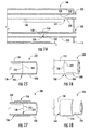
- an exemplary tube tip 230 comprises a radially extending mating surface 232 and a step 234 defined along the radially extending mating surface, wherein the downstream end 136 of the pre-mix tube 130 is seated adjacent to the step 234.
- the tube tip 230 may be fixedly connected to the pre-mix tube 130 via brazing, welding, adhesive cladding or by any means and/or process suitable for joining the two components.
- the tube tip 230 may extend through the aft plate 112 and/or the impingement plate 120.
- an exemplary tube tip 240 comprises a radially extending mating surface 242 that forms a butt joint 244 with the radially extending end surface 138 of the pre-mix tube.
- the tube tip comprises a radially extending mating surface that forms a butt joint with the radially extending end surface of the pre-mix tube.
- the tube tip 240 may be fixedly connected to the pre-mix tube 130 via brazing, welding, adhesive cladding or by any means and/or process suitable for joining the two components.
- the tube tip may extend through the aft plate 112 and/or the impingement plate 120.
- an exemplary tube tip 250 comprises a radially extending mating surface 252 that forms a joint 254 with the radially extending end surface 138 of the pre-mix tube 130.
- a coupling sleeve 256 circumferentially surrounds the joint 254.
- the coupling sleeve 256 may be fixedly connected to the pre-mix tube 130 via brazing, welding, adhesive cladding or by any means and/or process suitable for joining the two components.
- the tube tip may extend through the aft plate 112 and/or the impingement plate 120.
- the coupling sleeve 256 provides structural support the connection between the pre-mix tube 130 and the tube tip.
- the tube tips 200 may reduce costs currently associated with the repair and/or replacement of pre-mix tubes.
- the tube tips 200 provide a two part tubing system that allows for design flexibility in material selection which may enhance mechanical and thermal performance of the bundled tube fuel injector 100, thus increasing part life.
- Another technical benefit of the various tube tip geometries may include improvements in disassembly, repair and assembly time of the bundled tube fuel injector 100.
Landscapes
- Engineering & Computer Science (AREA)
- Chemical & Material Sciences (AREA)
- Combustion & Propulsion (AREA)
- Mechanical Engineering (AREA)
- General Engineering & Computer Science (AREA)
- Fuel-Injection Apparatus (AREA)
- Gas Burners (AREA)
Applications Claiming Priority (1)
| Application Number | Priority Date | Filing Date | Title |
|---|---|---|---|
| US14/105,327 US9423134B2 (en) | 2013-12-13 | 2013-12-13 | Bundled tube fuel injector with a multi-configuration tube tip |
Publications (2)
| Publication Number | Publication Date |
|---|---|
| EP2884183A1 true EP2884183A1 (de) | 2015-06-17 |
| EP2884183B1 EP2884183B1 (de) | 2016-09-21 |
Family
ID=52021078
Family Applications (1)
| Application Number | Title | Priority Date | Filing Date |
|---|---|---|---|
| EP14197247.1A Active EP2884183B1 (de) | 2013-12-13 | 2014-12-10 | Bündelrohrkraftstoffinjektor |
Country Status (3)
| Country | Link |
|---|---|
| US (1) | US9423134B2 (de) |
| EP (1) | EP2884183B1 (de) |
| CN (1) | CN104713129B (de) |
Cited By (1)
| Publication number | Priority date | Publication date | Assignee | Title |
|---|---|---|---|---|
| EP3961103A1 (de) * | 2020-08-28 | 2022-03-02 | General Electric Company | Verfahren zur wartung einer kraftstoffdüsenspitze |
Families Citing this family (14)
| Publication number | Priority date | Publication date | Assignee | Title |
|---|---|---|---|---|
| US9599343B2 (en) * | 2012-11-28 | 2017-03-21 | General Electric Company | Fuel nozzle for use in a turbine engine and method of assembly |
| US9664392B2 (en) * | 2013-12-13 | 2017-05-30 | General Electric Company | Bundled tube fuel injector with outer shroud and outer band connection |
| US9259807B2 (en) | 2013-12-13 | 2016-02-16 | General Electric Company | Method for repairing a bundled tube fuel injector |
| US20150167983A1 (en) * | 2013-12-13 | 2015-06-18 | General Electric Company | Bundled tube fuel injector tube tip |
| US10161626B2 (en) * | 2015-07-01 | 2018-12-25 | National Technology & Engineering Solutions Of Sandia, Llc | Ducted fuel injection |
| US20170350321A1 (en) * | 2016-06-02 | 2017-12-07 | General Electric Company | Bundled Tube Fuel Nozzle Assembly with Tube Extensions |
| US10669942B2 (en) | 2017-02-23 | 2020-06-02 | General Electric Company | Endcover assembly for a combustor |
| US11156360B2 (en) * | 2019-02-18 | 2021-10-26 | General Electric Company | Fuel nozzle assembly |
| US11060460B1 (en) | 2019-04-01 | 2021-07-13 | Marine Turbine Technologies, LLC | Fuel distribution system for gas turbine engine |
| KR102437977B1 (ko) * | 2021-01-18 | 2022-08-30 | 두산에너빌리티 주식회사 | 노즐 어셈블리, 연소기 및 이를 포함하는 가스터빈 |
| KR102583223B1 (ko) | 2022-01-28 | 2023-09-25 | 두산에너빌리티 주식회사 | 연소기용 노즐, 연소기 및 이를 포함하는 가스터빈 |
| US12083640B1 (en) | 2023-08-09 | 2024-09-10 | Ge Infrastructure Technology Llc | Methods of repairing tubes in bundled tube fuel injectors |
| US12103148B1 (en) | 2023-10-02 | 2024-10-01 | Ge Infrastructure Technology Llc | Aft inner cap plate removal method and tooling for a combustor with micromixer tubes |
| US12434362B2 (en) | 2023-10-02 | 2025-10-07 | Ge Infrastructure Technology Llc | Aft inner cap plate removal method and tooling for a combustor with micromixer tubes |
Citations (2)
| Publication number | Priority date | Publication date | Assignee | Title |
|---|---|---|---|---|
| EP2587153A2 (de) * | 2011-10-26 | 2013-05-01 | General Electric Company | Kraftstoffdüsenanordnung zur Verwendung in Turbinenmotoren und Verfahren zu ihrem Zusammenbau |
| US20130227951A1 (en) * | 2012-03-01 | 2013-09-05 | Solar Turbines Incorporated | Laser clad fuel injector premix barrel |
Family Cites Families (32)
| Publication number | Priority date | Publication date | Assignee | Title |
|---|---|---|---|---|
| US4100733A (en) * | 1976-10-04 | 1978-07-18 | United Technologies Corporation | Premix combustor |
| FR2648268B1 (de) | 1989-06-12 | 1991-09-27 | Framatome Sa | |
| US5094801A (en) | 1990-01-22 | 1992-03-10 | The Babcock & Wilcox Company | Two piece pressurizer heater sleeve |
| FR2666879B1 (fr) | 1990-09-19 | 1993-03-19 | Framatome Sa | Procede de remplacement d'un tube d'un echangeur de chaleur a tubes droits et utilisation de ce procede. |
| DE4236005C2 (de) | 1992-10-24 | 1994-08-25 | Bbc Reaktor Gmbh | Verfahren zum Austausch eines einen Deckel eines Kernreaktordruckbehälters durchsetzenden Stutzens |
| US5367768A (en) | 1992-12-17 | 1994-11-29 | Mpr Associates, Inc. | Methods of repairing inconel 600 nozzles of pressurized water reactor vessels |
| US5271048A (en) | 1992-12-21 | 1993-12-14 | B&W Nuclear Service Company | Replacement nozzle and method for replacing a nozzle in a pressure vessel |
| US5605361A (en) | 1994-05-06 | 1997-02-25 | Entergy Operations, Inc. | Replacement nozzle for pressure vessels and method of a attaching same |
| US5596873A (en) * | 1994-09-14 | 1997-01-28 | General Electric Company | Gas turbine combustor with a plurality of circumferentially spaced pre-mixers |
| US5833141A (en) * | 1997-05-30 | 1998-11-10 | General Electric Company | Anti-coking dual-fuel nozzle for a gas turbine combustor |
| US6345084B1 (en) | 1999-11-19 | 2002-02-05 | General Electric Company | Apparatus and methods for replacing a core spray T-box/thermal sleeve in a nuclear reactor |
| US6298667B1 (en) * | 2000-06-22 | 2001-10-09 | General Electric Company | Modular combustor dome |
| US7551705B2 (en) | 2003-12-11 | 2009-06-23 | Areva Np, Inc. | Fuel assembly top nozzle repair sleeve and method for repairing a fuel assembly |
| US7757491B2 (en) * | 2008-05-09 | 2010-07-20 | General Electric Company | Fuel nozzle for a gas turbine engine and method for fabricating the same |
| US8661779B2 (en) * | 2008-09-26 | 2014-03-04 | Siemens Energy, Inc. | Flex-fuel injector for gas turbines |
| US8209986B2 (en) * | 2008-10-29 | 2012-07-03 | General Electric Company | Multi-tube thermal fuse for nozzle protection from a flame holding or flashback event |
| US8539773B2 (en) * | 2009-02-04 | 2013-09-24 | General Electric Company | Premixed direct injection nozzle for highly reactive fuels |
| US20110197587A1 (en) * | 2010-02-18 | 2011-08-18 | General Electric Company | Multi-tube premixing injector |
| US8925324B2 (en) * | 2010-10-05 | 2015-01-06 | General Electric Company | Turbomachine including a mixing tube element having a vortex generator |
| US9506654B2 (en) * | 2011-08-19 | 2016-11-29 | General Electric Company | System and method for reducing combustion dynamics in a combustor |
| US20130283810A1 (en) * | 2012-04-30 | 2013-10-31 | General Electric Company | Combustion nozzle and a related method thereof |
| DE102012216080A1 (de) * | 2012-08-17 | 2014-02-20 | Dürr Systems GmbH | Brenner |
| US9353950B2 (en) * | 2012-12-10 | 2016-05-31 | General Electric Company | System for reducing combustion dynamics and NOx in a combustor |
| US9528444B2 (en) * | 2013-03-12 | 2016-12-27 | General Electric Company | System having multi-tube fuel nozzle with floating arrangement of mixing tubes |
| US9366439B2 (en) * | 2013-03-12 | 2016-06-14 | General Electric Company | Combustor end cover with fuel plenums |
| US9759425B2 (en) * | 2013-03-12 | 2017-09-12 | General Electric Company | System and method having multi-tube fuel nozzle with multiple fuel injectors |
| US9371997B2 (en) * | 2013-07-01 | 2016-06-21 | General Electric Company | System for supporting a bundled tube fuel injector within a combustor |
| US9476592B2 (en) * | 2013-09-19 | 2016-10-25 | General Electric Company | System for injecting fuel in a gas turbine combustor |
| US9664392B2 (en) * | 2013-12-13 | 2017-05-30 | General Electric Company | Bundled tube fuel injector with outer shroud and outer band connection |
| US20150167983A1 (en) * | 2013-12-13 | 2015-06-18 | General Electric Company | Bundled tube fuel injector tube tip |
| US9259807B2 (en) * | 2013-12-13 | 2016-02-16 | General Electric Company | Method for repairing a bundled tube fuel injector |
| US9528704B2 (en) * | 2014-02-21 | 2016-12-27 | General Electric Company | Combustor cap having non-round outlets for mixing tubes |
-
2013
- 2013-12-13 US US14/105,327 patent/US9423134B2/en active Active
-
2014
- 2014-12-10 EP EP14197247.1A patent/EP2884183B1/de active Active
- 2014-12-12 CN CN201410760483.5A patent/CN104713129B/zh active Active
Patent Citations (2)
| Publication number | Priority date | Publication date | Assignee | Title |
|---|---|---|---|---|
| EP2587153A2 (de) * | 2011-10-26 | 2013-05-01 | General Electric Company | Kraftstoffdüsenanordnung zur Verwendung in Turbinenmotoren und Verfahren zu ihrem Zusammenbau |
| US20130227951A1 (en) * | 2012-03-01 | 2013-09-05 | Solar Turbines Incorporated | Laser clad fuel injector premix barrel |
Cited By (2)
| Publication number | Priority date | Publication date | Assignee | Title |
|---|---|---|---|---|
| EP3961103A1 (de) * | 2020-08-28 | 2022-03-02 | General Electric Company | Verfahren zur wartung einer kraftstoffdüsenspitze |
| US11435081B2 (en) | 2020-08-28 | 2022-09-06 | General Electric Company | Methods of servicing a fuel nozzle tip |
Also Published As
| Publication number | Publication date |
|---|---|
| US9423134B2 (en) | 2016-08-23 |
| CN104713129B (zh) | 2019-02-19 |
| EP2884183B1 (de) | 2016-09-21 |
| US20150167981A1 (en) | 2015-06-18 |
| CN104713129A (zh) | 2015-06-17 |
Similar Documents
| Publication | Publication Date | Title |
|---|---|---|
| US10072847B2 (en) | Method for repairing a bundled tube fuel injector | |
| US9423134B2 (en) | Bundled tube fuel injector with a multi-configuration tube tip | |
| US9664392B2 (en) | Bundled tube fuel injector with outer shroud and outer band connection | |
| US9371997B2 (en) | System for supporting a bundled tube fuel injector within a combustor | |
| US20150167983A1 (en) | Bundled tube fuel injector tube tip | |
| US10087844B2 (en) | Bundled tube fuel nozzle assembly with liquid fuel capability | |
| US9291103B2 (en) | Fuel nozzle for a combustor of a gas turbine engine | |
| US9273868B2 (en) | System for supporting bundled tube segments within a combustor | |
| US20150027126A1 (en) | System for providing fuel to a combustor | |
| US9423136B2 (en) | Bundled tube fuel injector aft plate retention | |
| EP3339609A1 (de) | Montageanordnung für eine fluidleitung eines gasturbinenmotor | |
| EP2657610B1 (de) | Brennkammer und Verfahren zur Montage der Brennkammer | |
| US10634344B2 (en) | Fuel nozzle assembly with fuel purge | |
| US9400112B2 (en) | Method for disassembling a bundled tube fuel injector | |
| US9581335B2 (en) | Fuel nozzle tube retention | |
| US9322555B2 (en) | Cap assembly for a bundled tube fuel injector | |
| EP3943816B1 (de) | Brennkammer und kraftstoffverteilerleitung | |
| US20170356655A1 (en) | Fuel nozzle assembly with fuel inlet slots |
Legal Events
| Date | Code | Title | Description |
|---|---|---|---|
| PUAI | Public reference made under article 153(3) epc to a published international application that has entered the european phase |
Free format text: ORIGINAL CODE: 0009012 |
|
| 17P | Request for examination filed |
Effective date: 20141210 |
|
| AK | Designated contracting states |
Kind code of ref document: A1 Designated state(s): AL AT BE BG CH CY CZ DE DK EE ES FI FR GB GR HR HU IE IS IT LI LT LU LV MC MK MT NL NO PL PT RO RS SE SI SK SM TR |
|
| AX | Request for extension of the european patent |
Extension state: BA ME |
|
| R17P | Request for examination filed (corrected) |
Effective date: 20151217 |
|
| RBV | Designated contracting states (corrected) |
Designated state(s): AL AT BE BG CH CY CZ DE DK EE ES FI FR GB GR HR HU IE IS IT LI LT LU LV MC MK MT NL NO PL PT RO RS SE SI SK SM TR |
|
| GRAP | Despatch of communication of intention to grant a patent |
Free format text: ORIGINAL CODE: EPIDOSNIGR1 |
|
| INTG | Intention to grant announced |
Effective date: 20160520 |
|
| GRAS | Grant fee paid |
Free format text: ORIGINAL CODE: EPIDOSNIGR3 |
|
| GRAA | (expected) grant |
Free format text: ORIGINAL CODE: 0009210 |
|
| AK | Designated contracting states |
Kind code of ref document: B1 Designated state(s): AL AT BE BG CH CY CZ DE DK EE ES FI FR GB GR HR HU IE IS IT LI LT LU LV MC MK MT NL NO PL PT RO RS SE SI SK SM TR |
|
| REG | Reference to a national code |
Ref country code: GB Ref legal event code: FG4D |
|
| REG | Reference to a national code |
Ref country code: CH Ref legal event code: EP |
|
| REG | Reference to a national code |
Ref country code: AT Ref legal event code: REF Ref document number: 831364 Country of ref document: AT Kind code of ref document: T Effective date: 20161015 |
|
| REG | Reference to a national code |
Ref country code: IE Ref legal event code: FG4D |
|
| REG | Reference to a national code |
Ref country code: DE Ref legal event code: R096 Ref document number: 602014003830 Country of ref document: DE |
|
| REG | Reference to a national code |
Ref country code: FR Ref legal event code: PLFP Year of fee payment: 3 |
|
| REG | Reference to a national code |
Ref country code: LT Ref legal event code: MG4D Ref country code: NL Ref legal event code: MP Effective date: 20160921 |
|
| PG25 | Lapsed in a contracting state [announced via postgrant information from national office to epo] |
Ref country code: FI Free format text: LAPSE BECAUSE OF FAILURE TO SUBMIT A TRANSLATION OF THE DESCRIPTION OR TO PAY THE FEE WITHIN THE PRESCRIBED TIME-LIMIT Effective date: 20160921 Ref country code: NO Free format text: LAPSE BECAUSE OF FAILURE TO SUBMIT A TRANSLATION OF THE DESCRIPTION OR TO PAY THE FEE WITHIN THE PRESCRIBED TIME-LIMIT Effective date: 20161221 Ref country code: RS Free format text: LAPSE BECAUSE OF FAILURE TO SUBMIT A TRANSLATION OF THE DESCRIPTION OR TO PAY THE FEE WITHIN THE PRESCRIBED TIME-LIMIT Effective date: 20160921 Ref country code: LT Free format text: LAPSE BECAUSE OF FAILURE TO SUBMIT A TRANSLATION OF THE DESCRIPTION OR TO PAY THE FEE WITHIN THE PRESCRIBED TIME-LIMIT Effective date: 20160921 |
|
| REG | Reference to a national code |
Ref country code: AT Ref legal event code: MK05 Ref document number: 831364 Country of ref document: AT Kind code of ref document: T Effective date: 20160921 |
|
| PG25 | Lapsed in a contracting state [announced via postgrant information from national office to epo] |
Ref country code: GR Free format text: LAPSE BECAUSE OF FAILURE TO SUBMIT A TRANSLATION OF THE DESCRIPTION OR TO PAY THE FEE WITHIN THE PRESCRIBED TIME-LIMIT Effective date: 20161222 Ref country code: SE Free format text: LAPSE BECAUSE OF FAILURE TO SUBMIT A TRANSLATION OF THE DESCRIPTION OR TO PAY THE FEE WITHIN THE PRESCRIBED TIME-LIMIT Effective date: 20160921 Ref country code: NL Free format text: LAPSE BECAUSE OF FAILURE TO SUBMIT A TRANSLATION OF THE DESCRIPTION OR TO PAY THE FEE WITHIN THE PRESCRIBED TIME-LIMIT Effective date: 20160921 Ref country code: LV Free format text: LAPSE BECAUSE OF FAILURE TO SUBMIT A TRANSLATION OF THE DESCRIPTION OR TO PAY THE FEE WITHIN THE PRESCRIBED TIME-LIMIT Effective date: 20160921 |
|
| PG25 | Lapsed in a contracting state [announced via postgrant information from national office to epo] |
Ref country code: EE Free format text: LAPSE BECAUSE OF FAILURE TO SUBMIT A TRANSLATION OF THE DESCRIPTION OR TO PAY THE FEE WITHIN THE PRESCRIBED TIME-LIMIT Effective date: 20160921 Ref country code: RO Free format text: LAPSE BECAUSE OF FAILURE TO SUBMIT A TRANSLATION OF THE DESCRIPTION OR TO PAY THE FEE WITHIN THE PRESCRIBED TIME-LIMIT Effective date: 20160921 |
|
| PG25 | Lapsed in a contracting state [announced via postgrant information from national office to epo] |
Ref country code: IS Free format text: LAPSE BECAUSE OF FAILURE TO SUBMIT A TRANSLATION OF THE DESCRIPTION OR TO PAY THE FEE WITHIN THE PRESCRIBED TIME-LIMIT Effective date: 20170121 Ref country code: BE Free format text: LAPSE BECAUSE OF FAILURE TO SUBMIT A TRANSLATION OF THE DESCRIPTION OR TO PAY THE FEE WITHIN THE PRESCRIBED TIME-LIMIT Effective date: 20160921 Ref country code: AT Free format text: LAPSE BECAUSE OF FAILURE TO SUBMIT A TRANSLATION OF THE DESCRIPTION OR TO PAY THE FEE WITHIN THE PRESCRIBED TIME-LIMIT Effective date: 20160921 Ref country code: ES Free format text: LAPSE BECAUSE OF FAILURE TO SUBMIT A TRANSLATION OF THE DESCRIPTION OR TO PAY THE FEE WITHIN THE PRESCRIBED TIME-LIMIT Effective date: 20160921 Ref country code: PT Free format text: LAPSE BECAUSE OF FAILURE TO SUBMIT A TRANSLATION OF THE DESCRIPTION OR TO PAY THE FEE WITHIN THE PRESCRIBED TIME-LIMIT Effective date: 20170123 Ref country code: SM Free format text: LAPSE BECAUSE OF FAILURE TO SUBMIT A TRANSLATION OF THE DESCRIPTION OR TO PAY THE FEE WITHIN THE PRESCRIBED TIME-LIMIT Effective date: 20160921 Ref country code: BG Free format text: LAPSE BECAUSE OF FAILURE TO SUBMIT A TRANSLATION OF THE DESCRIPTION OR TO PAY THE FEE WITHIN THE PRESCRIBED TIME-LIMIT Effective date: 20161221 Ref country code: CZ Free format text: LAPSE BECAUSE OF FAILURE TO SUBMIT A TRANSLATION OF THE DESCRIPTION OR TO PAY THE FEE WITHIN THE PRESCRIBED TIME-LIMIT Effective date: 20160921 Ref country code: SK Free format text: LAPSE BECAUSE OF FAILURE TO SUBMIT A TRANSLATION OF THE DESCRIPTION OR TO PAY THE FEE WITHIN THE PRESCRIBED TIME-LIMIT Effective date: 20160921 Ref country code: PL Free format text: LAPSE BECAUSE OF FAILURE TO SUBMIT A TRANSLATION OF THE DESCRIPTION OR TO PAY THE FEE WITHIN THE PRESCRIBED TIME-LIMIT Effective date: 20160921 |
|
| REG | Reference to a national code |
Ref country code: DE Ref legal event code: R097 Ref document number: 602014003830 Country of ref document: DE |
|
| PLBE | No opposition filed within time limit |
Free format text: ORIGINAL CODE: 0009261 |
|
| STAA | Information on the status of an ep patent application or granted ep patent |
Free format text: STATUS: NO OPPOSITION FILED WITHIN TIME LIMIT |
|
| PG25 | Lapsed in a contracting state [announced via postgrant information from national office to epo] |
Ref country code: DK Free format text: LAPSE BECAUSE OF FAILURE TO SUBMIT A TRANSLATION OF THE DESCRIPTION OR TO PAY THE FEE WITHIN THE PRESCRIBED TIME-LIMIT Effective date: 20160921 |
|
| 26N | No opposition filed |
Effective date: 20170622 |
|
| PG25 | Lapsed in a contracting state [announced via postgrant information from national office to epo] |
Ref country code: MC Free format text: LAPSE BECAUSE OF FAILURE TO SUBMIT A TRANSLATION OF THE DESCRIPTION OR TO PAY THE FEE WITHIN THE PRESCRIBED TIME-LIMIT Effective date: 20160921 |
|
| REG | Reference to a national code |
Ref country code: IE Ref legal event code: MM4A |
|
| PG25 | Lapsed in a contracting state [announced via postgrant information from national office to epo] |
Ref country code: LU Free format text: LAPSE BECAUSE OF NON-PAYMENT OF DUE FEES Effective date: 20161210 |
|
| PG25 | Lapsed in a contracting state [announced via postgrant information from national office to epo] |
Ref country code: IE Free format text: LAPSE BECAUSE OF NON-PAYMENT OF DUE FEES Effective date: 20161210 Ref country code: SI Free format text: LAPSE BECAUSE OF FAILURE TO SUBMIT A TRANSLATION OF THE DESCRIPTION OR TO PAY THE FEE WITHIN THE PRESCRIBED TIME-LIMIT Effective date: 20160921 |
|
| REG | Reference to a national code |
Ref country code: FR Ref legal event code: PLFP Year of fee payment: 4 |
|
| PG25 | Lapsed in a contracting state [announced via postgrant information from national office to epo] |
Ref country code: HU Free format text: LAPSE BECAUSE OF FAILURE TO SUBMIT A TRANSLATION OF THE DESCRIPTION OR TO PAY THE FEE WITHIN THE PRESCRIBED TIME-LIMIT; INVALID AB INITIO Effective date: 20141210 |
|
| PG25 | Lapsed in a contracting state [announced via postgrant information from national office to epo] |
Ref country code: HR Free format text: LAPSE BECAUSE OF FAILURE TO SUBMIT A TRANSLATION OF THE DESCRIPTION OR TO PAY THE FEE WITHIN THE PRESCRIBED TIME-LIMIT Effective date: 20160921 Ref country code: MK Free format text: LAPSE BECAUSE OF FAILURE TO SUBMIT A TRANSLATION OF THE DESCRIPTION OR TO PAY THE FEE WITHIN THE PRESCRIBED TIME-LIMIT Effective date: 20160921 Ref country code: CY Free format text: LAPSE BECAUSE OF FAILURE TO SUBMIT A TRANSLATION OF THE DESCRIPTION OR TO PAY THE FEE WITHIN THE PRESCRIBED TIME-LIMIT Effective date: 20160921 |
|
| REG | Reference to a national code |
Ref country code: CH Ref legal event code: PL |
|
| PG25 | Lapsed in a contracting state [announced via postgrant information from national office to epo] |
Ref country code: MT Free format text: LAPSE BECAUSE OF NON-PAYMENT OF DUE FEES Effective date: 20161210 |
|
| PG25 | Lapsed in a contracting state [announced via postgrant information from national office to epo] |
Ref country code: AL Free format text: LAPSE BECAUSE OF FAILURE TO SUBMIT A TRANSLATION OF THE DESCRIPTION OR TO PAY THE FEE WITHIN THE PRESCRIBED TIME-LIMIT Effective date: 20160921 Ref country code: TR Free format text: LAPSE BECAUSE OF FAILURE TO SUBMIT A TRANSLATION OF THE DESCRIPTION OR TO PAY THE FEE WITHIN THE PRESCRIBED TIME-LIMIT Effective date: 20160921 |
|
| PG25 | Lapsed in a contracting state [announced via postgrant information from national office to epo] |
Ref country code: CH Free format text: LAPSE BECAUSE OF NON-PAYMENT OF DUE FEES Effective date: 20171231 Ref country code: LI Free format text: LAPSE BECAUSE OF NON-PAYMENT OF DUE FEES Effective date: 20171231 |
|
| GBPC | Gb: european patent ceased through non-payment of renewal fee |
Effective date: 20181210 |
|
| PG25 | Lapsed in a contracting state [announced via postgrant information from national office to epo] |
Ref country code: GB Free format text: LAPSE BECAUSE OF NON-PAYMENT OF DUE FEES Effective date: 20181210 |
|
| REG | Reference to a national code |
Ref country code: DE Ref legal event code: R081 Ref document number: 602014003830 Country of ref document: DE Owner name: GENERAL ELECTRIC TECHNOLOGY GMBH, CH Free format text: FORMER OWNER: GENERAL ELECTRIC COMPANY, SCHENECTADY, NY, US |
|
| PGFP | Annual fee paid to national office [announced via postgrant information from national office to epo] |
Ref country code: DE Payment date: 20251126 Year of fee payment: 12 |
|
| PGFP | Annual fee paid to national office [announced via postgrant information from national office to epo] |
Ref country code: IT Payment date: 20251119 Year of fee payment: 12 |
|
| PGFP | Annual fee paid to national office [announced via postgrant information from national office to epo] |
Ref country code: FR Payment date: 20251120 Year of fee payment: 12 |