EP2884233A2 - Mesure de paramètres dans un entraînement électromagnétique d'un appareil de commutation - Google Patents
Mesure de paramètres dans un entraînement électromagnétique d'un appareil de commutation Download PDFInfo
- Publication number
- EP2884233A2 EP2884233A2 EP14197061.6A EP14197061A EP2884233A2 EP 2884233 A2 EP2884233 A2 EP 2884233A2 EP 14197061 A EP14197061 A EP 14197061A EP 2884233 A2 EP2884233 A2 EP 2884233A2
- Authority
- EP
- European Patent Office
- Prior art keywords
- drive
- coil
- electromagnetic drive
- electromagnetic
- measuring device
- Prior art date
- Legal status (The legal status is an assumption and is not a legal conclusion. Google has not performed a legal analysis and makes no representation as to the accuracy of the status listed.)
- Granted
Links
Images



Classifications
-
- H—ELECTRICITY
- H01—ELECTRIC ELEMENTS
- H01H—ELECTRIC SWITCHES; RELAYS; SELECTORS; EMERGENCY PROTECTIVE DEVICES
- H01H71/00—Details of the protective switches or relays covered by groups H01H73/00 - H01H83/00
- H01H71/04—Means for indicating condition of the switching device
-
- G—PHYSICS
- G01—MEASURING; TESTING
- G01K—MEASURING TEMPERATURE; MEASURING QUANTITY OF HEAT; THERMALLY-SENSITIVE ELEMENTS NOT OTHERWISE PROVIDED FOR
- G01K7/00—Measuring temperature based on the use of electric or magnetic elements directly sensitive to heat ; Power supply therefor, e.g. using thermoelectric elements
- G01K7/16—Measuring temperature based on the use of electric or magnetic elements directly sensitive to heat ; Power supply therefor, e.g. using thermoelectric elements using resistive elements
-
- G—PHYSICS
- G01—MEASURING; TESTING
- G01R—MEASURING ELECTRIC VARIABLES; MEASURING MAGNETIC VARIABLES
- G01R31/00—Arrangements for testing electric properties; Arrangements for locating electric faults; Arrangements for electrical testing characterised by what is being tested not provided for elsewhere
- G01R31/327—Testing of circuit interrupters, switches or circuit-breakers
- G01R31/3277—Testing of circuit interrupters, switches or circuit-breakers of low voltage devices, e.g. domestic or industrial devices, such as motor protections, relays, rotation switches
- G01R31/3278—Testing of circuit interrupters, switches or circuit-breakers of low voltage devices, e.g. domestic or industrial devices, such as motor protections, relays, rotation switches of relays, solenoids or reed switches
-
- H—ELECTRICITY
- H01—ELECTRIC ELEMENTS
- H01F—MAGNETS; INDUCTANCES; TRANSFORMERS; SELECTION OF MATERIALS FOR THEIR MAGNETIC PROPERTIES
- H01F7/00—Magnets
- H01F7/06—Electromagnets; Actuators including electromagnets
- H01F7/08—Electromagnets; Actuators including electromagnets with armatures
- H01F7/18—Circuit arrangements for obtaining desired operating characteristics, e.g. for slow operation, for sequential energisation of windings, for high-speed energisation of windings
- H01F7/1844—Monitoring or fail-safe circuits
-
- H—ELECTRICITY
- H01—ELECTRIC ELEMENTS
- H01H—ELECTRIC SWITCHES; RELAYS; SELECTORS; EMERGENCY PROTECTIVE DEVICES
- H01H47/00—Circuit arrangements not adapted to a particular application of the relay and designed to obtain desired operating characteristics or to provide energising current
- H01H47/002—Monitoring or fail-safe circuits
-
- H—ELECTRICITY
- H01—ELECTRIC ELEMENTS
- H01H—ELECTRIC SWITCHES; RELAYS; SELECTORS; EMERGENCY PROTECTIVE DEVICES
- H01H47/00—Circuit arrangements not adapted to a particular application of the relay and designed to obtain desired operating characteristics or to provide energising current
- H01H47/007—Circuit arrangements not adapted to a particular application of the relay and designed to obtain desired operating characteristics or to provide energising current with galvanic isolation between controlling and controlled circuit, e.g. transformer relay
-
- H—ELECTRICITY
- H01—ELECTRIC ELEMENTS
- H01H—ELECTRIC SWITCHES; RELAYS; SELECTORS; EMERGENCY PROTECTIVE DEVICES
- H01H47/00—Circuit arrangements not adapted to a particular application of the relay and designed to obtain desired operating characteristics or to provide energising current
- H01H47/02—Circuit arrangements not adapted to a particular application of the relay and designed to obtain desired operating characteristics or to provide energising current for modifying the operation of the relay
-
- G—PHYSICS
- G01—MEASURING; TESTING
- G01D—MEASURING NOT SPECIALLY ADAPTED FOR A SPECIFIC VARIABLE; ARRANGEMENTS FOR MEASURING TWO OR MORE VARIABLES NOT COVERED IN A SINGLE OTHER SUBCLASS; TARIFF METERING APPARATUS; MEASURING OR TESTING NOT OTHERWISE PROVIDED FOR
- G01D3/00—Indicating or recording apparatus with provision for the special purposes referred to in the subgroups
- G01D3/02—Indicating or recording apparatus with provision for the special purposes referred to in the subgroups with provision for altering or correcting the law of variation
- G01D3/022—Indicating or recording apparatus with provision for the special purposes referred to in the subgroups with provision for altering or correcting the law of variation having an ideal characteristic, map or correction data stored in a digital memory
-
- G—PHYSICS
- G01—MEASURING; TESTING
- G01D—MEASURING NOT SPECIALLY ADAPTED FOR A SPECIFIC VARIABLE; ARRANGEMENTS FOR MEASURING TWO OR MORE VARIABLES NOT COVERED IN A SINGLE OTHER SUBCLASS; TARIFF METERING APPARATUS; MEASURING OR TESTING NOT OTHERWISE PROVIDED FOR
- G01D5/00—Mechanical means for transferring the output of a sensing member; Means for converting the output of a sensing member to another variable where the form or nature of the sensing member does not constrain the means for converting; Transducers not specially adapted for a specific variable
- G01D5/12—Mechanical means for transferring the output of a sensing member; Means for converting the output of a sensing member to another variable where the form or nature of the sensing member does not constrain the means for converting; Transducers not specially adapted for a specific variable using electric or magnetic means
- G01D5/14—Mechanical means for transferring the output of a sensing member; Means for converting the output of a sensing member to another variable where the form or nature of the sensing member does not constrain the means for converting; Transducers not specially adapted for a specific variable using electric or magnetic means influencing the magnitude of a current or voltage
- G01D5/20—Mechanical means for transferring the output of a sensing member; Means for converting the output of a sensing member to another variable where the form or nature of the sensing member does not constrain the means for converting; Transducers not specially adapted for a specific variable using electric or magnetic means influencing the magnitude of a current or voltage by varying inductance, e.g. by a movable armature
-
- G—PHYSICS
- G01—MEASURING; TESTING
- G01K—MEASURING TEMPERATURE; MEASURING QUANTITY OF HEAT; THERMALLY-SENSITIVE ELEMENTS NOT OTHERWISE PROVIDED FOR
- G01K2217/00—Temperature measurement using electric or magnetic components already present in the system to be measured
-
- G—PHYSICS
- G01—MEASURING; TESTING
- G01R—MEASURING ELECTRIC VARIABLES; MEASURING MAGNETIC VARIABLES
- G01R31/00—Arrangements for testing electric properties; Arrangements for locating electric faults; Arrangements for electrical testing characterised by what is being tested not provided for elsewhere
- G01R31/50—Testing of electric apparatus, lines, cables or components for short-circuits, continuity, leakage current or incorrect line connections
- G01R31/72—Testing of electric windings
-
- H—ELECTRICITY
- H01—ELECTRIC ELEMENTS
- H01H—ELECTRIC SWITCHES; RELAYS; SELECTORS; EMERGENCY PROTECTIVE DEVICES
- H01H47/00—Circuit arrangements not adapted to a particular application of the relay and designed to obtain desired operating characteristics or to provide energising current
- H01H47/02—Circuit arrangements not adapted to a particular application of the relay and designed to obtain desired operating characteristics or to provide energising current for modifying the operation of the relay
- H01H47/04—Circuit arrangements not adapted to a particular application of the relay and designed to obtain desired operating characteristics or to provide energising current for modifying the operation of the relay for holding armature in attracted position, e.g. when initial energising circuit is interrupted; for maintaining armature in attracted position, e.g. with reduced energising current
- H01H2047/046—Circuit arrangements not adapted to a particular application of the relay and designed to obtain desired operating characteristics or to provide energising current for modifying the operation of the relay for holding armature in attracted position, e.g. when initial energising circuit is interrupted; for maintaining armature in attracted position, e.g. with reduced energising current with measuring of the magnetic field, e.g. of the magnetic flux, for the control of coil current
Definitions
- the invention relates to a device for measuring quantity measurement in the electromagnetic drive of a switching device, in particular a contactor, a control and a regulating device with such a measured quantity detection device and switching devices with such a control or regulating device.
- the European patent application EP0549911A1 describes a device for monitoring the inductance of a coil, which is not part of a resonant circuit, with a second coil, which is connected in series with the coil, and a resonant circuit, by the connection of a capacitor to the second coil or optionally with a third coil formed in a mutually inductive relationship with the second coil, is formed, so that the second and third coil act as primary and secondary coils of a transformer.
- the device can be used as a so-called integral control in the closed loop of the storage of an object with the first coil.
- the output of the amplitude detector required in such an arrangement may be successively supplied to an error detector and an integrator become.
- EMC electromagnetic compatibility
- special modules such as frequency generators and resonance modules are needed. which makes the implementation of this circuit consuming.
- the object of the present invention is now to propose a device for measuring quantity measurement in the electromagnetic drive of a switching device, which can in principle also be used with single-coil electromagnetic drives and with a comparison with that from the European patent application EP0549911A1 known prior art technically less complex circuit can be implemented.
- An underlying idea of the present invention is to connect an inductive transformer in series with a coil of an electromagnetic drive of a switching device, and via this transformer measurement variables of the electromagnetic drive without a complex resonant circuit as in the European patent application EP0549911A1 known device to detect directly on the secondary side of the transformer with a digital electronic measuring device, which in particular requires no additional components such as frequency generators or resonant components, so that during operation, the EMC is less affected.
- the digital electronic measuring device can be implemented by a microprocessor or microcontroller configured by means of a corresponding firmware for the measuring tasks, if necessary together with an upstream signal processing in the form of impedance matching or offset generation.
- the inductive transformer is in this case dimensioned such that it influences the drive as little as possible.
- a transformer can also be used in an electromagnetic drive having only one coil. In principle, however, it can be used with almost any type of electromagnetic switchgear drive, ie also with drives with separate holding and tightening coil.
- the measuring quantity detecting device according to the invention can be implemented without additional contacts on the board with the control electronics of the switching device, in particular by the transformer is integrated directly into the power circuit of an electromagnetic drive. As a result, the production costs and the number of error sources can be reduced.
- An embodiment of the invention now relates to a device for measuring quantity measurement in the electromagnetic drive of a switching device with an inductive transformer whose primary side is connected in series with a coil of the electromagnetic drive, and connected to the secondary side of the transformer digital electronic measuring device for measuring one on the secondary side transmitted voltage U L2 and for determining at least one measured variable of the electromagnetic drive depending on the measured voltage U L2 and known values of the transformer and / or the drive according to at least one determination and calculation function.
- the measuring device may be configured to determine the course of the current i and to determine an installation position of the switching device depending on the determined course.
- the measuring device can determine the mounting or installation position of a switching device by determining the point in time when the voltage U L2 is approximately zero, because then the electromagnetic drive is in motion and the current responsible for the movement reaches its provisional maximum point , which depends on the installation or mounting position of the drive.
- the measuring device may be configured to detect the current i when the electromagnetic drive is operated in a holding state in which the drive is not in motion, and to determine the temperature of the coil of the electromagnetic drive depending on the detected current.
- the measuring device may also be configured to detect an armature core shock by evaluating the trace of the measured voltage U L2 by detecting an armature core surge when the voltage U L2 makes a jump from negative to positive ,
- the measuring device may also be configured to determine the time of occurrence of an armature core shock and to determine a state of the mechanics of the electromagnetic drive depending on the determined time.
- the determined state can be output by the measuring device, for example via an interface. If, for example, the armature-core shock is detected at a very early point in time after the drive has been energized, it can be assumed that the impression forces of springs of the drive, for example when a spring breaks, are too low. If, on the other hand, the armature-core shock is detected at a relatively late point in time, it can be assumed, for example, that the mechanics of the drive have increased frictional resistance.
- the digital electronic measuring device may be configured to implement a time measuring function to determine the time of an armature core shock after energizing the drive and to check whether the determined time is within a predetermined range, which is a predetermined, in particular good state the drive mechanism includes. This can be determined by the measuring device, whether the mechanics of the electromagnetic drive still meets the requirements that are defined by the predetermined time range.
- L 1 denotes the inductance of the primary side of the transformer
- ⁇ denotes the factor of transmission of the voltage U L1 on the primary side of the transformer to the voltage U L2
- U PWM is the one across the series connection of the coil (14) of the Electromagnetic drive and the primary side (12) of the transformer (10) sloping and by the measuring device (18) determined voltage referred to.
- the measuring device can be configured to determine an air gap in the electromagnetic drive based on a characteristic s (L drive ) of the inductance of the coil of the electromagnetic drive.
- a further embodiment of the invention relates to a device for controlling the electromagnetic drive of a switching device, in particular a contactor, comprising a drive coil system, in particular with a pull-in coil and a holding coil, with a measured-quantity detecting device which is configured to perform an armature core shock
- a drive electronics for controlling the electromagnetic drive which is configured in that, upon detection of an armature core shock, it switches over energization of the drive coil system from a tightening operation to a holding operation, in particular switching off the energization of the tightening coil and switching on energizing of the holding coil.
- a further embodiment of the invention relates to a switching device, in particular contactor, with an electromagnetic switching drive having a drive coil system, in particular with a tightening coil and a holding coil, and a control device according to the invention and as described above for controlling the energization of the drive coil system, in particular the tightening coil and the holding coil.
- a further embodiment of the invention relates to a device for controlling the electromagnetic drive of a switching device, in particular a contactor, with a measured quantity detecting device according to the invention and as described above for determining the inductance L driving the coil of the electromagnetic drive, the air gap in the electromagnetic drive and / or of the magnetic linking flux ⁇ drive is configured in the electromagnetic drive, and a control electronics for controlling the electromagnetic drive, which is configured such that it energizes a coil of the electromagnetic drive depending on the determined inductance L drive , the determined air gap and / or the determined magnetic chain flow ⁇ Drive regulates.
- the invention relates in one embodiment, a switching device, in particular contactor, with an electromagnetic drive and a control device according to the invention and as described above for controlling the electromagnetic drive.
- FIG. 1 shows the driving of a drive coil 14 with the inductance L drive of an electromagnetic drive of a switching device and the integration of a device for measuring quantity detection according to the invention.
- the primary side 12, ie the primary-side coil with the inductance L 1 and the number of turns N 1 , of a transformer 10 is connected in series with the drive coil 14. Furthermore, to the two coils 12 and 14, the load path of a field effect transistor (FET) 20 connected in series.
- FET field effect transistor
- the series connection of the two coils 12 and 14 and the load path of the FET 20 is supplied by a DC voltage source 28 with DC. Parallel to the DC voltage source 28, a capacitor 26 is connected for buffering.
- a freewheeling diode 24 connects the terminals of the series connection of the coil 12 and 14, so that when switching off the voltage applied to the coils 12 and 14, an induced current can flow through the freewheeling diode 24.
- the drive coil 14 in order to close the switching contacts of the switching device, the drive coil 14 must be energized. During the tightening operation, a higher force is required to close the switch contacts than during the holding process, in which it is sufficient to energize the drive coil so that the switch contacts are kept closed. In general, therefore, the load path of the FET 20 is controlled by a drive electronics 30 of the drive generated pulse-width-modulated (PWM) control signal 22 during the tightening process such that the flowing of the DC voltage source 28 through the drive coil 14 current i so it is great that a sufficiently strong magnetic field for overcoming the force required to close the switching contacts is built up by the drive coil 14.
- PWM pulse-width-modulated
- the current i can be reduced so far that a sufficient strength for holding the switch contacts in the closed state magnetic field is generated by the drive coil 14.
- the control of the current i can be done for example by a modulation of the pulse width of the PWM control signal 22. It is also possible to fully switch on the FET 20 during the tightening process, and to switch to a PWM control of the FET 20 only during the holding process.
- U L2 N 2 ⁇ d ⁇ ⁇ Ü ⁇ bert rager d ⁇ t
- U L ⁇ 2 L 1 ⁇ N 2 N 1 ⁇ d ⁇ i d ⁇ t
- the voltage U L2 now contains information about the tightening or holding current i, the armature core shock and the inductance L drive the drive coil 14 and thus a movement of the electromagnetic drive, which affects the inductance L drive the drive coil 14.
- a digital electronic measuring device 18 is now provided to measure the voltage transmitted to the secondary side U L2 and at least one of the aforementioned measured variable of the electromagnetic drive depending on the measured voltage U L2 and known values of the transformer and / or the drive according to at least one determination and calculate function.
- the digital electronic measuring device may implement one or more of the following detection and calculation functions:
- the digital electronic measuring device 18 can determine the armature core shock.
- the armature core shock occurs when the armature and the core of the electromagnetic drive of the switching device meet at the end of the tightening process and can not move on, typically after the switch contacts are fully closed.
- Fig. 2 For example, typical traces of voltage U L2 during a pull-in operation and pull-in current i over time are shown. The curve of the starting current i shown in the diagram above shows that the current first rises to a vertex and then drops again to a relatively low value at the time t A when an armature-core shock occurs. At this time, the voltage U L2 makes a jump, as can be seen from the voltage waveform shown below.
- the measuring device 18 can therefore detect such a jump in the voltage U L2 and thus an armature-core shock.
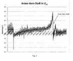
- Fig. 3 shows a diagram with the course of the voltage detected by the device U L2 , from which the armature-core shock at the voltage jump at about the time at 1.4E-02 seconds emerges.
- the electronic measuring device 18 can also determine the inductance L drive of the drive coil 14 and thus its movement as follows: Frequency components which can be evaluated as follows are contained in the PWM control signal 22 for driving the drive.
- the PWM control signal 22 has a predetermined period T independent of the voltage U PWM (see Fig. 1 ) on.
- the predetermined period T is the sum of a time t on , during which the PWM drive signal 22 has a first value for turning on the FET 20, and the time period t off , during which the PWM drive signal 22 has a second value for locking the FET 20.
- the voltage U L1 is transmitted with a known and constant factor ⁇ to the secondary side of the transformer 10 in the voltage U L2 .
- FFT Fast Fourier Transform
- the inductance L 1 of the primary side of the transformer 10 is known and constant, while the inductance L drive of the drive coil 14 changes during the tightening process and can be calculated with the above equation of the electronic measuring device at each time of the tightening operation.
- the digital electronic measuring device 18 can determine the air gap in the drive from the calculated inductance L drive of the drive coil 14 in the knowledge of a characteristic s (L drive ) of the drive, which can be stored for example in a memory of the measuring device 18 and the reference between the air gap and inductance , determine.
- L drive characteristic s
- All of the parameters determined by the digital electronic measuring device 18 can be output by the latter in particular to the control electronics 30.
- the digital electronic measuring device 18 can be implemented by a processor, in particular a microprocessor or microcontroller, which executes a firmware of the switching device which implements the above-described detection and calculation functions.
- the voltage U L2 can be digitized for this purpose by the digital electronic measuring device 18, for example via an integrated analog-to-digital converter.
- the electronic measuring device in hardware, for example by an ASIC (Application Sepcific Integrated Circuit) or a (F) PGA (Field Programmable Gate Array).
- the parameters that can be calculated by the digital electronic measuring device 18 can be used for various applications in a switching device, as will be explained below.
- the detection of an armature core shock by the electronic measuring device 18 can be supplied as a signal of the control electronics 30 for controlling the electromagnetic drive, in particular with a tightening and a holding coil.
- the control electronics 30 can switch upon energization of the coil system from tightening to hold upon receipt of the signal, in particular turn off energization of the tightening coil and turn on energizing the holding coil. Through this control, the switching process from tightening to holding can be better adapted to the electromagnetic drive, in particular to a behavior changed over the course of the operating time. In addition, energy can be saved when putting on. In addition, power components are less heavily loaded in the switching device, as in example a timed changeover that is not adapted to a changed behavior of the drive.
- Control tasks may also be implemented based on the parameters calculable by the electronic measurement device 18.
- the magnetic linking flux berechn drive calculated by the measuring device 18 can be supplied to the drive electronics 30 for controlling the electromagnetic drive, as is also the case in the German patent application mentioned above DE 10 2012 106 922.0 is explained.
- a control can also be implemented with the movement of the electromagnetic drive as a controlled variable. For example, via the inductance L drive of the coil of the electromagnetic drive and / or the air gap in the electromagnetic drive, which are determined by the measuring device 18, the movement of the electromagnetic drive can be precisely adjusted and regulated to a predetermined movement. By accurately controlling the movement, the electromagnetic drive can be accurately adjusted, which also offers advantages in the design of the main contacts of a switching device. The force required to move the contacts can thereby be accurately and automatically adjusted to the mounting position of the switching device, such as a contactor. Since also temperature influences are compensated, a temperature compensation can be omitted.
- Contactor drives typically have two metallic components: the armature and the core.
- the drive coil is usually mounted on the anchor.
- the anchor is connected to a contact bridge.
- impression springs By means of impression springs, an air gap is created between the armature and the core, in the non-excited state of the drive coil. If a sufficiently large current flows through the coil, a magnetic field is formed which is dimensioned such that the core is pulled onto the armature. Due to the magnetic field, therefore, a force F mag must be generated which is sufficient to accelerate the core and the bridge (ie, its mass) and to overcome the forces of the impression springs.
- the gravitational force F g can also influence the contactor drive. Is the mounting position like this?
- Fig. 4 are the curves 34, 36 shown by drive currents in two different mounting positions of a contactor. Furthermore, the simulated curve 32 of the measured voltage U L2 is shown. From it not only the current in the drive can be calculated, but also the time of the turning point can be determined. Since U L2 is the derivative of the current, this voltage is zero in the inflection point. This is the time at which the determined current is assessed and the controller must decide whether the force must be adjusted.
- the two current curves 34, 36 in Fig. 4 were taken in different mounting positions of a contactor.
- the voltage UL2 - curve 32 - belongs to the current curve 36 and represents the so-called wall mounting.
- the current curve 34 has been recorded in a so-called table mounting.
- the effects are already measurable here. Due to the low mass in the drive, the effect of gravity is not so strong. If drives with larger masses are used, the effects are much more pronounced.
- the strengths of the impression springs in conjunction with the set drive forces are decisive for the switch-on time, ie the time it takes the contactor to close the contacts after applying a switching command. If the switching time changes, this can be an indication be for a defect. For example, if a spring breaks its counterforce. The contactor switches faster due to the constant magnetic forces. These too high forces can be too large for the rest of the mechanics in the medium time view and damage them.
- the monitoring of the switching time can be done with the present invention by detecting the armature core shock. If this is detected too early or too late, the controller of the contactor knows that there is a fault in the force setting and the contactor must be repaired or replaced. This can be passed on via suitable interfaces.
- One way to access this information is to energize the drive with holding energy.
- the drive of the contactor is not yet set in motion.
- the applied voltage is known and the self-adjusting current can be measured.
- the resistance of the drive can be determined and used for temperature compensation.
Landscapes
- Physics & Mathematics (AREA)
- General Physics & Mathematics (AREA)
- Electromagnetism (AREA)
- Engineering & Computer Science (AREA)
- Power Engineering (AREA)
- Relay Circuits (AREA)
- Keying Circuit Devices (AREA)
Priority Applications (1)
| Application Number | Priority Date | Filing Date | Title |
|---|---|---|---|
| PL14197061T PL2884233T3 (pl) | 2013-12-16 | 2014-12-09 | Rejestrowanie wielkości pomiarowej w napędzie elektromagnetycznym łącznika |
Applications Claiming Priority (1)
| Application Number | Priority Date | Filing Date | Title |
|---|---|---|---|
| DE102013114076 | 2013-12-16 |
Publications (3)
| Publication Number | Publication Date |
|---|---|
| EP2884233A2 true EP2884233A2 (fr) | 2015-06-17 |
| EP2884233A3 EP2884233A3 (fr) | 2015-11-04 |
| EP2884233B1 EP2884233B1 (fr) | 2021-09-01 |
Family
ID=52101088
Family Applications (1)
| Application Number | Title | Priority Date | Filing Date |
|---|---|---|---|
| EP14197061.6A Active EP2884233B1 (fr) | 2013-12-16 | 2014-12-09 | Mesure de paramètres dans un entraînement électromagnétique d'un appareil de commutation |
Country Status (2)
| Country | Link |
|---|---|
| EP (1) | EP2884233B1 (fr) |
| PL (1) | PL2884233T3 (fr) |
Cited By (5)
| Publication number | Priority date | Publication date | Assignee | Title |
|---|---|---|---|---|
| CN108054065A (zh) * | 2018-01-08 | 2018-05-18 | 银河电气有限公司 | 一种自愈式快速投切开关 |
| CN109036884A (zh) * | 2018-09-19 | 2018-12-18 | 宁夏力成电气集团有限公司 | 一种智能型高压真空断路器及其机械特性参数确定方法 |
| EP3680925A1 (fr) * | 2019-01-11 | 2020-07-15 | Siemens Nederland N.V. | Interrupteur |
| EP3806126A1 (fr) * | 2019-10-07 | 2021-04-14 | TE Connectivity Germany GmbH | Ensemble et procédé de surveillance de l'état d'un relais |
| WO2026008439A1 (fr) * | 2024-07-02 | 2026-01-08 | Eaton Intelligent Power Limited | Procédé de détermination d'usure de contact d'un dispositif de commutation, et dispositif de commutation |
Citations (2)
| Publication number | Priority date | Publication date | Assignee | Title |
|---|---|---|---|---|
| EP0549911A1 (fr) | 1992-01-03 | 1993-07-07 | British Nuclear Fuels PLC | Dispositif de surveillance d'une inductivité |
| DE102012106922A1 (de) | 2012-07-30 | 2014-01-30 | Eaton Electrical Ip Gmbh & Co. Kg | Vorrichtung zum Regeln des elektromagnetischen Antriebs eines Schaltgeräts, insbesondere eines Schützes |
Family Cites Families (3)
| Publication number | Priority date | Publication date | Assignee | Title |
|---|---|---|---|---|
| US3337777A (en) * | 1964-09-14 | 1967-08-22 | Westinghouse Electric Corp | Frequency responsive device utilizing a saturable core reactor and scr means |
| FR2803956B3 (fr) * | 2000-01-13 | 2002-06-14 | Systemes Et Conversion Ind D E | Dispositif et procede pour alimenter une bobine de commande d'un contacteur electrique, notamment d'un contacteur de puissance |
| DE102007063479A1 (de) * | 2007-12-20 | 2008-11-20 | Siemens Ag | Verfahren und Schaltungsanordnung zum Erzeugen eines eine Endlage eines Elektromagneten anzeigenden Signals |
-
2014
- 2014-12-09 PL PL14197061T patent/PL2884233T3/pl unknown
- 2014-12-09 EP EP14197061.6A patent/EP2884233B1/fr active Active
Patent Citations (2)
| Publication number | Priority date | Publication date | Assignee | Title |
|---|---|---|---|---|
| EP0549911A1 (fr) | 1992-01-03 | 1993-07-07 | British Nuclear Fuels PLC | Dispositif de surveillance d'une inductivité |
| DE102012106922A1 (de) | 2012-07-30 | 2014-01-30 | Eaton Electrical Ip Gmbh & Co. Kg | Vorrichtung zum Regeln des elektromagnetischen Antriebs eines Schaltgeräts, insbesondere eines Schützes |
Cited By (9)
| Publication number | Priority date | Publication date | Assignee | Title |
|---|---|---|---|---|
| CN108054065A (zh) * | 2018-01-08 | 2018-05-18 | 银河电气有限公司 | 一种自愈式快速投切开关 |
| CN109036884A (zh) * | 2018-09-19 | 2018-12-18 | 宁夏力成电气集团有限公司 | 一种智能型高压真空断路器及其机械特性参数确定方法 |
| CN109036884B (zh) * | 2018-09-19 | 2023-11-10 | 宁夏力成电气集团有限公司 | 一种智能型高压真空断路器及其机械特性参数确定方法 |
| EP3680925A1 (fr) * | 2019-01-11 | 2020-07-15 | Siemens Nederland N.V. | Interrupteur |
| WO2020144338A1 (fr) * | 2019-01-11 | 2020-07-16 | Siemens Nederland N.V. | Commutateur |
| US20220102088A1 (en) * | 2019-01-11 | 2022-03-31 | Siemens Nederland N.V. | Switch |
| US11742159B2 (en) * | 2019-01-11 | 2023-08-29 | Siemens Nederland N.V. | Switch |
| EP3806126A1 (fr) * | 2019-10-07 | 2021-04-14 | TE Connectivity Germany GmbH | Ensemble et procédé de surveillance de l'état d'un relais |
| WO2026008439A1 (fr) * | 2024-07-02 | 2026-01-08 | Eaton Intelligent Power Limited | Procédé de détermination d'usure de contact d'un dispositif de commutation, et dispositif de commutation |
Also Published As
| Publication number | Publication date |
|---|---|
| EP2884233A3 (fr) | 2015-11-04 |
| EP2884233B1 (fr) | 2021-09-01 |
| PL2884233T3 (pl) | 2022-01-17 |
Similar Documents
| Publication | Publication Date | Title |
|---|---|---|
| EP0886762B1 (fr) | Procede et dispositif pour controler un detecteur | |
| DE3843138C2 (fr) | ||
| DE3942836C2 (fr) | ||
| DE3708892C2 (de) | Strommeßeinrichtung, insbesondere zur Bestimmung des Motorstroms eines Gleichstrommotors | |
| EP1872378B1 (fr) | Detection de position sans capteur dans un actionneur electromagnetique | |
| EP2884233B1 (fr) | Mesure de paramètres dans un entraînement électromagnétique d'un appareil de commutation | |
| DE102015214925B4 (de) | Verfahren zum Betrieb einer Magnetresonanzeinrichtung und Magnetresonanzeinrichtung | |
| WO2022218553A1 (fr) | Procédé de détection d'une défaillance dans un relais | |
| DE102008036767A1 (de) | Halbleitervorrichtung | |
| EP2265964B1 (fr) | Procédé et dispositif de mesure du courant dans des lignes de phase | |
| EP2845211A1 (fr) | Surveillance d'un relais électromagnétique | |
| EP1165944A1 (fr) | Procede permettant de determiner la position d'un induit | |
| EP2546852B1 (fr) | Relais de sécurité bistable | |
| EP0050705B1 (fr) | Méthode et circuit pour mesurer sans contact des courants continus et alternatifs, en particulier des valeurs instantanées de courant | |
| DE102004025156B3 (de) | Verfahren zur Fehlerkorrektur eines Wegsensorsignals | |
| DE2545325B2 (de) | Schaltungsanordnung zur Messung des Isolationswiderstandes erdfreier Starkstromschaltungen | |
| DE102008023198A1 (de) | Hydraulikventilsteuergerät und Verfahren zum Überprüfen eines Hydraulikventilsteuergeräts | |
| DE102010043744A1 (de) | Schaltungsanordnung sowie Verfahren zur Überwachung des Schaltens einer Energiequelle zur Versorgung eines Elektroantriebs | |
| DE102005041823B3 (de) | Steuergerät zum Betrieb wenigstens eines Kraftstoffinjektors einer Brennkraftmaschine | |
| EP0865660B1 (fr) | Dispositif de commande pour appareils de commutation | |
| DE102012220474A1 (de) | Verfahren und Vorrichtung zur Überwachung eines Zustands eines Transformators | |
| DE19843678A1 (de) | Verfahren zur Bereitstellung eines Ausgangssignals mit einem gewünschten Wert einer Kenngröße am Ausgang eines Schaltnetzteils und Schaltung zur Durchführung des Verfahrens | |
| EP0553451B1 (fr) | Dispositif pour contrÔler le fonctionnement d'inductivités | |
| DE102018207417A1 (de) | Bestimmung einer Kenngröße eines magnetischen Schaltventils | |
| DE102024134095B4 (de) | Vorrichtung und Verfahren zur Ermittlung von Schaltzeitpunkten eines elektromagnetischen Aktuators, Computerprogramm |
Legal Events
| Date | Code | Title | Description |
|---|---|---|---|
| PUAI | Public reference made under article 153(3) epc to a published international application that has entered the european phase |
Free format text: ORIGINAL CODE: 0009012 |
|
| 17P | Request for examination filed |
Effective date: 20141209 |
|
| AK | Designated contracting states |
Kind code of ref document: A2 Designated state(s): AL AT BE BG CH CY CZ DE DK EE ES FI FR GB GR HR HU IE IS IT LI LT LU LV MC MK MT NL NO PL PT RO RS SE SI SK SM TR |
|
| AX | Request for extension of the european patent |
Extension state: BA ME |
|
| PUAL | Search report despatched |
Free format text: ORIGINAL CODE: 0009013 |
|
| AK | Designated contracting states |
Kind code of ref document: A3 Designated state(s): AL AT BE BG CH CY CZ DE DK EE ES FI FR GB GR HR HU IE IS IT LI LT LU LV MC MK MT NL NO PL PT RO RS SE SI SK SM TR |
|
| AX | Request for extension of the european patent |
Extension state: BA ME |
|
| RIC1 | Information provided on ipc code assigned before grant |
Ipc: H01H 47/22 20060101ALI20150929BHEP Ipc: H01H 47/02 20060101ALI20150929BHEP Ipc: G01K 7/16 20060101ALI20150929BHEP Ipc: G01R 31/06 20060101ALI20150929BHEP Ipc: H01H 47/00 20060101AFI20150929BHEP Ipc: H01H 1/00 20060101ALI20150929BHEP Ipc: H01F 7/18 20060101ALI20150929BHEP Ipc: G01D 3/02 20060101ALI20150929BHEP Ipc: H01H 71/04 20060101ALI20150929BHEP Ipc: H01H 11/00 20060101ALI20150929BHEP Ipc: G01D 5/20 20060101ALI20150929BHEP Ipc: G01R 31/327 20060101ALI20150929BHEP |
|
| RBV | Designated contracting states (corrected) |
Designated state(s): AL AT BE BG CH CY CZ DE DK EE ES FI FR GB GR HR HU IE IS IT LI LT LU LV MC MK MT NL NO PL PT RO RS SE SI SK SM TR |
|
| RAP1 | Party data changed (applicant data changed or rights of an application transferred) |
Owner name: EATON INTELLIGENT POWER LIMITED |
|
| STAA | Information on the status of an ep patent application or granted ep patent |
Free format text: STATUS: REQUEST FOR EXAMINATION WAS MADE |
|
| R17P | Request for examination filed (corrected) |
Effective date: 20160505 |
|
| REG | Reference to a national code |
Ref country code: DE Ref legal event code: R079 Ref document number: 502014015839 Country of ref document: DE Free format text: PREVIOUS MAIN CLASS: G01D0005200000 Ipc: H01H0047040000 |
|
| GRAP | Despatch of communication of intention to grant a patent |
Free format text: ORIGINAL CODE: EPIDOSNIGR1 |
|
| STAA | Information on the status of an ep patent application or granted ep patent |
Free format text: STATUS: GRANT OF PATENT IS INTENDED |
|
| RIC1 | Information provided on ipc code assigned before grant |
Ipc: H01H 47/02 20060101ALI20210211BHEP Ipc: G01R 31/327 20060101ALI20210211BHEP Ipc: H01H 47/00 20060101ALI20210211BHEP Ipc: H01H 71/04 20060101ALI20210211BHEP Ipc: H01H 47/04 20060101AFI20210211BHEP Ipc: H01F 7/18 20060101ALI20210211BHEP Ipc: G01D 3/02 20060101ALI20210211BHEP Ipc: G01D 5/20 20060101ALI20210211BHEP Ipc: G01K 7/16 20060101ALI20210211BHEP |
|
| INTG | Intention to grant announced |
Effective date: 20210226 |
|
| GRAS | Grant fee paid |
Free format text: ORIGINAL CODE: EPIDOSNIGR3 |
|
| GRAA | (expected) grant |
Free format text: ORIGINAL CODE: 0009210 |
|
| STAA | Information on the status of an ep patent application or granted ep patent |
Free format text: STATUS: THE PATENT HAS BEEN GRANTED |
|
| AK | Designated contracting states |
Kind code of ref document: B1 Designated state(s): AL AT BE BG CH CY CZ DE DK EE ES FI FR GB GR HR HU IE IS IT LI LT LU LV MC MK MT NL NO PL PT RO RS SE SI SK SM TR |
|
| REG | Reference to a national code |
Ref country code: GB Ref legal event code: FG4D Free format text: NOT ENGLISH |
|
| REG | Reference to a national code |
Ref country code: CH Ref legal event code: EP Ref country code: AT Ref legal event code: REF Ref document number: 1427098 Country of ref document: AT Kind code of ref document: T Effective date: 20210915 |
|
| REG | Reference to a national code |
Ref country code: DE Ref legal event code: R096 Ref document number: 502014015839 Country of ref document: DE |
|
| REG | Reference to a national code |
Ref country code: IE Ref legal event code: FG4D Free format text: LANGUAGE OF EP DOCUMENT: GERMAN |
|
| REG | Reference to a national code |
Ref country code: LT Ref legal event code: MG9D |
|
| REG | Reference to a national code |
Ref country code: NL Ref legal event code: MP Effective date: 20210901 |
|
| PG25 | Lapsed in a contracting state [announced via postgrant information from national office to epo] |
Ref country code: RS Free format text: LAPSE BECAUSE OF FAILURE TO SUBMIT A TRANSLATION OF THE DESCRIPTION OR TO PAY THE FEE WITHIN THE PRESCRIBED TIME-LIMIT Effective date: 20210901 Ref country code: SE Free format text: LAPSE BECAUSE OF FAILURE TO SUBMIT A TRANSLATION OF THE DESCRIPTION OR TO PAY THE FEE WITHIN THE PRESCRIBED TIME-LIMIT Effective date: 20210901 Ref country code: HR Free format text: LAPSE BECAUSE OF FAILURE TO SUBMIT A TRANSLATION OF THE DESCRIPTION OR TO PAY THE FEE WITHIN THE PRESCRIBED TIME-LIMIT Effective date: 20210901 Ref country code: NO Free format text: LAPSE BECAUSE OF FAILURE TO SUBMIT A TRANSLATION OF THE DESCRIPTION OR TO PAY THE FEE WITHIN THE PRESCRIBED TIME-LIMIT Effective date: 20211201 Ref country code: FI Free format text: LAPSE BECAUSE OF FAILURE TO SUBMIT A TRANSLATION OF THE DESCRIPTION OR TO PAY THE FEE WITHIN THE PRESCRIBED TIME-LIMIT Effective date: 20210901 Ref country code: ES Free format text: LAPSE BECAUSE OF FAILURE TO SUBMIT A TRANSLATION OF THE DESCRIPTION OR TO PAY THE FEE WITHIN THE PRESCRIBED TIME-LIMIT Effective date: 20210901 Ref country code: BG Free format text: LAPSE BECAUSE OF FAILURE TO SUBMIT A TRANSLATION OF THE DESCRIPTION OR TO PAY THE FEE WITHIN THE PRESCRIBED TIME-LIMIT Effective date: 20211201 Ref country code: LT Free format text: LAPSE BECAUSE OF FAILURE TO SUBMIT A TRANSLATION OF THE DESCRIPTION OR TO PAY THE FEE WITHIN THE PRESCRIBED TIME-LIMIT Effective date: 20210901 |
|
| PG25 | Lapsed in a contracting state [announced via postgrant information from national office to epo] |
Ref country code: LV Free format text: LAPSE BECAUSE OF FAILURE TO SUBMIT A TRANSLATION OF THE DESCRIPTION OR TO PAY THE FEE WITHIN THE PRESCRIBED TIME-LIMIT Effective date: 20210901 Ref country code: GR Free format text: LAPSE BECAUSE OF FAILURE TO SUBMIT A TRANSLATION OF THE DESCRIPTION OR TO PAY THE FEE WITHIN THE PRESCRIBED TIME-LIMIT Effective date: 20211202 |
|
| PG25 | Lapsed in a contracting state [announced via postgrant information from national office to epo] |
Ref country code: IS Free format text: LAPSE BECAUSE OF FAILURE TO SUBMIT A TRANSLATION OF THE DESCRIPTION OR TO PAY THE FEE WITHIN THE PRESCRIBED TIME-LIMIT Effective date: 20220101 Ref country code: SM Free format text: LAPSE BECAUSE OF FAILURE TO SUBMIT A TRANSLATION OF THE DESCRIPTION OR TO PAY THE FEE WITHIN THE PRESCRIBED TIME-LIMIT Effective date: 20210901 Ref country code: SK Free format text: LAPSE BECAUSE OF FAILURE TO SUBMIT A TRANSLATION OF THE DESCRIPTION OR TO PAY THE FEE WITHIN THE PRESCRIBED TIME-LIMIT Effective date: 20210901 Ref country code: RO Free format text: LAPSE BECAUSE OF FAILURE TO SUBMIT A TRANSLATION OF THE DESCRIPTION OR TO PAY THE FEE WITHIN THE PRESCRIBED TIME-LIMIT Effective date: 20210901 Ref country code: PT Free format text: LAPSE BECAUSE OF FAILURE TO SUBMIT A TRANSLATION OF THE DESCRIPTION OR TO PAY THE FEE WITHIN THE PRESCRIBED TIME-LIMIT Effective date: 20220103 Ref country code: NL Free format text: LAPSE BECAUSE OF FAILURE TO SUBMIT A TRANSLATION OF THE DESCRIPTION OR TO PAY THE FEE WITHIN THE PRESCRIBED TIME-LIMIT Effective date: 20210901 Ref country code: EE Free format text: LAPSE BECAUSE OF FAILURE TO SUBMIT A TRANSLATION OF THE DESCRIPTION OR TO PAY THE FEE WITHIN THE PRESCRIBED TIME-LIMIT Effective date: 20210901 Ref country code: CZ Free format text: LAPSE BECAUSE OF FAILURE TO SUBMIT A TRANSLATION OF THE DESCRIPTION OR TO PAY THE FEE WITHIN THE PRESCRIBED TIME-LIMIT Effective date: 20210901 Ref country code: AL Free format text: LAPSE BECAUSE OF FAILURE TO SUBMIT A TRANSLATION OF THE DESCRIPTION OR TO PAY THE FEE WITHIN THE PRESCRIBED TIME-LIMIT Effective date: 20210901 |
|
| REG | Reference to a national code |
Ref country code: DE Ref legal event code: R097 Ref document number: 502014015839 Country of ref document: DE |
|
| PLBE | No opposition filed within time limit |
Free format text: ORIGINAL CODE: 0009261 |
|
| STAA | Information on the status of an ep patent application or granted ep patent |
Free format text: STATUS: NO OPPOSITION FILED WITHIN TIME LIMIT |
|
| PG25 | Lapsed in a contracting state [announced via postgrant information from national office to epo] |
Ref country code: MC Free format text: LAPSE BECAUSE OF FAILURE TO SUBMIT A TRANSLATION OF THE DESCRIPTION OR TO PAY THE FEE WITHIN THE PRESCRIBED TIME-LIMIT Effective date: 20210901 Ref country code: DK Free format text: LAPSE BECAUSE OF FAILURE TO SUBMIT A TRANSLATION OF THE DESCRIPTION OR TO PAY THE FEE WITHIN THE PRESCRIBED TIME-LIMIT Effective date: 20210901 |
|
| REG | Reference to a national code |
Ref country code: CH Ref legal event code: PL |
|
| 26N | No opposition filed |
Effective date: 20220602 |
|
| GBPC | Gb: european patent ceased through non-payment of renewal fee |
Effective date: 20211209 |
|
| PG25 | Lapsed in a contracting state [announced via postgrant information from national office to epo] |
Ref country code: SI Free format text: LAPSE BECAUSE OF FAILURE TO SUBMIT A TRANSLATION OF THE DESCRIPTION OR TO PAY THE FEE WITHIN THE PRESCRIBED TIME-LIMIT Effective date: 20210901 |
|
| REG | Reference to a national code |
Ref country code: BE Ref legal event code: MM Effective date: 20211231 |
|
| PG25 | Lapsed in a contracting state [announced via postgrant information from national office to epo] |
Ref country code: LU Free format text: LAPSE BECAUSE OF NON-PAYMENT OF DUE FEES Effective date: 20211209 Ref country code: IE Free format text: LAPSE BECAUSE OF NON-PAYMENT OF DUE FEES Effective date: 20211209 Ref country code: GB Free format text: LAPSE BECAUSE OF NON-PAYMENT OF DUE FEES Effective date: 20211209 |
|
| PG25 | Lapsed in a contracting state [announced via postgrant information from national office to epo] |
Ref country code: BE Free format text: LAPSE BECAUSE OF NON-PAYMENT OF DUE FEES Effective date: 20211231 |
|
| PG25 | Lapsed in a contracting state [announced via postgrant information from national office to epo] |
Ref country code: LI Free format text: LAPSE BECAUSE OF NON-PAYMENT OF DUE FEES Effective date: 20211231 Ref country code: CH Free format text: LAPSE BECAUSE OF NON-PAYMENT OF DUE FEES Effective date: 20211231 |
|
| REG | Reference to a national code |
Ref country code: AT Ref legal event code: MM01 Ref document number: 1427098 Country of ref document: AT Kind code of ref document: T Effective date: 20211209 |
|
| PG25 | Lapsed in a contracting state [announced via postgrant information from national office to epo] |
Ref country code: AT Free format text: LAPSE BECAUSE OF NON-PAYMENT OF DUE FEES Effective date: 20211209 |
|
| PG25 | Lapsed in a contracting state [announced via postgrant information from national office to epo] |
Ref country code: HU Free format text: LAPSE BECAUSE OF FAILURE TO SUBMIT A TRANSLATION OF THE DESCRIPTION OR TO PAY THE FEE WITHIN THE PRESCRIBED TIME-LIMIT; INVALID AB INITIO Effective date: 20141209 |
|
| P01 | Opt-out of the competence of the unified patent court (upc) registered |
Effective date: 20230521 |
|
| PG25 | Lapsed in a contracting state [announced via postgrant information from national office to epo] |
Ref country code: CY Free format text: LAPSE BECAUSE OF FAILURE TO SUBMIT A TRANSLATION OF THE DESCRIPTION OR TO PAY THE FEE WITHIN THE PRESCRIBED TIME-LIMIT Effective date: 20210901 |
|
| PG25 | Lapsed in a contracting state [announced via postgrant information from national office to epo] |
Ref country code: MK Free format text: LAPSE BECAUSE OF FAILURE TO SUBMIT A TRANSLATION OF THE DESCRIPTION OR TO PAY THE FEE WITHIN THE PRESCRIBED TIME-LIMIT Effective date: 20210901 |
|
| PG25 | Lapsed in a contracting state [announced via postgrant information from national office to epo] |
Ref country code: MT Free format text: LAPSE BECAUSE OF FAILURE TO SUBMIT A TRANSLATION OF THE DESCRIPTION OR TO PAY THE FEE WITHIN THE PRESCRIBED TIME-LIMIT Effective date: 20210901 |
|
| PG25 | Lapsed in a contracting state [announced via postgrant information from national office to epo] |
Ref country code: TR Free format text: LAPSE BECAUSE OF FAILURE TO SUBMIT A TRANSLATION OF THE DESCRIPTION OR TO PAY THE FEE WITHIN THE PRESCRIBED TIME-LIMIT Effective date: 20210901 |
|
| PGFP | Annual fee paid to national office [announced via postgrant information from national office to epo] |
Ref country code: DE Payment date: 20251126 Year of fee payment: 12 |
|
| PGFP | Annual fee paid to national office [announced via postgrant information from national office to epo] |
Ref country code: IT Payment date: 20251119 Year of fee payment: 12 |
|
| PGFP | Annual fee paid to national office [announced via postgrant information from national office to epo] |
Ref country code: FR Payment date: 20251120 Year of fee payment: 12 |
|
| PGFP | Annual fee paid to national office [announced via postgrant information from national office to epo] |
Ref country code: PL Payment date: 20251119 Year of fee payment: 12 |