EP2884236A1 - Capteur inductif de couple et d'angle de rotation doté d'une unité d'indication de position à circuit oscillant - Google Patents
Capteur inductif de couple et d'angle de rotation doté d'une unité d'indication de position à circuit oscillant Download PDFInfo
- Publication number
- EP2884236A1 EP2884236A1 EP14197720.7A EP14197720A EP2884236A1 EP 2884236 A1 EP2884236 A1 EP 2884236A1 EP 14197720 A EP14197720 A EP 14197720A EP 2884236 A1 EP2884236 A1 EP 2884236A1
- Authority
- EP
- European Patent Office
- Prior art keywords
- voltage
- sensor according
- frequency
- coil
- encoder unit
- Prior art date
- Legal status (The legal status is an assumption and is not a legal conclusion. Google has not performed a legal analysis and makes no representation as to the accuracy of the status listed.)
- Ceased
Links
- 230000001939 inductive effect Effects 0.000 title claims description 15
- 230000005284 excitation Effects 0.000 claims abstract description 19
- 239000004020 conductor Substances 0.000 claims description 10
- 239000003990 capacitor Substances 0.000 claims description 4
- 238000004804 winding Methods 0.000 description 18
- 238000011156 evaluation Methods 0.000 description 4
- 238000005259 measurement Methods 0.000 description 4
- 230000000737 periodic effect Effects 0.000 description 4
- 238000010276 construction Methods 0.000 description 1
- 230000008878 coupling Effects 0.000 description 1
- 238000010168 coupling process Methods 0.000 description 1
- 238000005859 coupling reaction Methods 0.000 description 1
- 230000001419 dependent effect Effects 0.000 description 1
- 230000010355 oscillation Effects 0.000 description 1
Images

Classifications
-
- G—PHYSICS
- G01—MEASURING; TESTING
- G01D—MEASURING NOT SPECIALLY ADAPTED FOR A SPECIFIC VARIABLE; ARRANGEMENTS FOR MEASURING TWO OR MORE VARIABLES NOT COVERED IN A SINGLE OTHER SUBCLASS; TARIFF METERING APPARATUS; MEASURING OR TESTING NOT OTHERWISE PROVIDED FOR
- G01D5/00—Mechanical means for transferring the output of a sensing member; Means for converting the output of a sensing member to another variable where the form or nature of the sensing member does not constrain the means for converting; Transducers not specially adapted for a specific variable
- G01D5/12—Mechanical means for transferring the output of a sensing member; Means for converting the output of a sensing member to another variable where the form or nature of the sensing member does not constrain the means for converting; Transducers not specially adapted for a specific variable using electric or magnetic means
- G01D5/14—Mechanical means for transferring the output of a sensing member; Means for converting the output of a sensing member to another variable where the form or nature of the sensing member does not constrain the means for converting; Transducers not specially adapted for a specific variable using electric or magnetic means influencing the magnitude of a current or voltage
- G01D5/20—Mechanical means for transferring the output of a sensing member; Means for converting the output of a sensing member to another variable where the form or nature of the sensing member does not constrain the means for converting; Transducers not specially adapted for a specific variable using electric or magnetic means influencing the magnitude of a current or voltage by varying inductance, e.g. by a movable armature
- G01D5/204—Mechanical means for transferring the output of a sensing member; Means for converting the output of a sensing member to another variable where the form or nature of the sensing member does not constrain the means for converting; Transducers not specially adapted for a specific variable using electric or magnetic means influencing the magnitude of a current or voltage by varying inductance, e.g. by a movable armature by influencing the mutual induction between two or more coils
-
- G—PHYSICS
- G01—MEASURING; TESTING
- G01L—MEASURING FORCE, STRESS, TORQUE, WORK, MECHANICAL POWER, MECHANICAL EFFICIENCY, OR FLUID PRESSURE
- G01L3/00—Measuring torque, work, mechanical power, or mechanical efficiency, in general
- G01L3/02—Rotary-transmission dynamometers
- G01L3/04—Rotary-transmission dynamometers wherein the torque-transmitting element comprises a torsionally-flexible shaft
- G01L3/10—Rotary-transmission dynamometers wherein the torque-transmitting element comprises a torsionally-flexible shaft involving electric or magnetic means for indicating
- G01L3/109—Rotary-transmission dynamometers wherein the torque-transmitting element comprises a torsionally-flexible shaft involving electric or magnetic means for indicating involving measuring phase difference of two signals or pulse trains
Definitions
- the invention relates to a rotation angle sensor for detecting the rotation angle or a torque of a rotating element according to the preamble of the independent claims.
- an inductive position detector with a first inductive device and a second inductive device wherein the first inductive device comprises a passive resonant circuit and the second inductive device defines the measuring path and comprises at least two receiving windings.
- the second inductive device is configured to induce an alternating current in the passive resonant circuit in use such that the alternating current induced in the passive resonant circuit induces an alternating signal in each receive coil due to the mutual inductance between the receiving turns and the passive resonant circuit, indicative of these signals are for the position of the first inductive device on the measuring path.
- the object of the invention is to develop the known principle for a rotation angle sensor or a torque sensor.
- the invention is based on the basic idea of equipping the position encoder unit with a plurality of resonant circuits, which can be identified by means of the receiver coil on the basis of its natural frequency.
- the relative position of the oscillating circuits relative to one another does not change, so that it is possible to deduce the position of the other oscillating circuits based on a measurement of the position of one oscillating circuit.
- the principle can be used for both a rotational angle and a torque sensor. It is advantageous to use two or more receiver coils. In the following description, reference will therefore be made to a plurality of receiving coils. Subsequent embodiments can in principle also be carried out with a receiver coil.
- the position encoder unit is connected to the element to be measured, for example a rotating shaft or a torsion element, and reflects the movement or deformation of this element. By detecting the absolute position or the relative movement of the moving element to the receiving coils of the corresponding measured variable can be detected via the position encoder unit either relative to the receiving coil or absolute with respect to a reference point.
- the position encoder unit is a separate from the excitation coil and the receiving coil part, which is, for example, arranged in parallel adjacent to the coils.
- An advantageous embodiment of the rotation angle sensor has an encoder unit with a carrier body, where the resonant circuits are arranged uniformly around a point of rotation.
- the measuring range of 360 ° can be divided in this way into several sectors or segments, so that when detecting a resonant circuit, a conclusion can be drawn on the respective circular sector or circular segment.
- An advantageous embodiment of the sensor according to the invention is designed such that the resonant circuit has at least one capacitive and one inductive element.
- An advantageous embodiment of the sensor according to the invention is designed such that the capacitive element is a capacitor and / or the inductive element is a current conductor.
- the capacitor and the inductive element may be embodied as printed on a printed circuit conductor or conductor tracks. This allows, in particular in connection with an annular carrier body of the position encoder unit, a particularly variable utilization of the mounting surface on the carrier body.
- the shape of the oscillating circuits can be variably adapted to the respective requirements.
- An advantageous embodiment of the sensor according to the invention is designed such that the resonant circuits each have a start and end point, wherein the starting and end points of the resonant circuits, preferably along a movement path, are arranged offset from each other. In this way, a particularly clear distinction between the respective resonant circuits is possible.
- An advantageous embodiment of the sensor according to the invention is designed such that the natural frequency of the resonant circuit is determined by means of the shape of the current conductor.
- the history forms can, for example, map a periodic function.
- the current conductors have a sinusoidal, cosine, trapezoidal, triangular, or rectangular profile.
- An advantageous embodiment of the sensor according to the invention is designed such that the natural frequency of the resonant circuit is determined as a function of the exciter frequency. This embodiment is particularly advantageous when the frequency of the AC voltage can not be set arbitrarily.
- An advantageous embodiment of the sensor according to the invention is designed such that the AC voltage has a voltage frequency which is adjustable in different frequencies. In this way it is possible to set the frequency of the AC voltage and thus also the frequency of the exciter field according to the natural frequencies of the resonant circuits.
- An advantageous embodiment of the sensor according to the invention is designed such that the voltage frequency is adjusted by adding a plurality of voltage frequencies.
- An advantageous embodiment of the sensor according to the invention is designed such that the voltage frequency is alternately adjustable in different frequencies. By means of this embodiment, it is possible to detect certain oscillating circuits alternately one behind the other.
- An advantageous embodiment of the sensor according to the invention is designed such that the voltage frequency is set as a function of the natural frequency of the resonant circuits or the natural frequency is set in dependence of the differently adjustable voltage frequencies.
- FIG. 1 shows a circuit arrangement 1 for operating a sensor 2 according to the invention in a schematic representation.
- the circuit arrangement has a voltage source 3, the sensor 2 and an evaluation unit 4.
- the arrangement may, for example, in an electric motor, for. B. DC motor, be installed.
- the voltage source 3 is electrically connected to the excitation coil 20 and supplies it with an AC voltage U ⁇ to generate a field corresponding to the AC voltage U ⁇ exciter field.
- the AC voltage U ⁇ has a voltage frequency f, which is variably adjustable and can be set in different voltage frequencies or frequencies.
- the alternating voltage can be set, for example, alternately in different frequencies. This can be done like this take place that the voltage frequency f is set by adding a plurality of voltage frequencies f1, f2.
- the voltage source 3 initially two AC voltage generators 5a and 5b, each generating an AC voltage in different frequencies f1, f2.
- This embodiment has the advantage that the AC voltage U ⁇ is easily changed by varying the sum of parts.
- the output signals of the voltage generators 5a and 5b are supplied to an adder 6.
- the sum of the output signals are supplied to a driver unit 7, which generates the AC voltage U ⁇ from this signal and supplies it to the exciter coil 20.
- a driver unit 7 which generates the AC voltage U ⁇ from this signal and supplies it to the exciter coil 20.
- the sensor 2 essentially comprises the exciter coil 20, an oscillator unit 30 and two receiver coils 40a, 40b.
- FIG. 1 the arrangement of the excitation coil 20, the position encoder unit 30 and the receiving coils 40a, 40b is shown schematically. In a preferred arrangement, s. FIGS. 4 and 5 , The receiver coil and the exciter coil are arranged on a carrier body and the position encoder unit arranged in parallel adjacent to the coils or their carrier body. This also applies to that FIG. 1 related embodiment accordingly.
- the excitation coil 20 is preferably formed as a printed circuit board printed on a printed circuit board and arranged around the receiving coils 40a, 40b, so that the exciting field generated by the AC voltage induces a voltage in the receiving coils 40a, 40b.
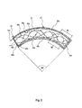
- the excitation coil 20 has a winding 21 which extends over a circle segment.
- an embodiment of the exciter and Receiver coils over a full circumference The winding 21 is wound over two tracks, wherein the connection points 22 are arranged on the outside.
- the exciter coil 20 is connected to the voltage source 3 via the connection points 22.
- the excitation coil 20 in each case has a rectilinear boundary 25a, 25b, which delimit with two circular arc-shaped sections 26a, 26b a region in which the receiver coils 40a, 40b are arranged. In this way, it is ensured that the receiver coils 40a, 40b are inductively coupled to the exciter coil 20.
- the receiving coil 40a, 40b each have a winding 43a, 43b.
- the windings 43a, 43b have a sinusoidal or cosinusoidal course. Also conceivable are other periodic shapes, as shown in the other embodiments.
- the windings 43a, 43b have a starting point 41a, 41b located at one end of the circle segment.
- the windings 43a, 43b run from there according to their periodic shape along the circle segment to the other end of the circle segment. From the other end, the windings 43a, 43b return like a reflected wave to the first end of the circle segment.
- the period length of the windings is designed such that an integer multiple of the period fits within the circular segment, as in the case of the receiving coil 40a.
- the winding 43b is guided inwardly over a substantially portion substantially along the winding of the exciting coil 20. From there, the winding 43b runs according to the predetermined periodic shape. The end of the winding 43a, 43b forms an end point 42a, 42b, respectively. Via the starting and end points 41a, 42a, 41b, 42b, the outgoing voltage Uout1 ⁇ , Uout2 ⁇ is tapped from the receiving coils.
- the receiving coils 40a, 40b have a plurality of measuring fields, in FIG. 2 exemplified by M1, M2.
- the measuring fields each have a winding direction corresponding to the running direction of the windings 43a, 43b.
- the winding directions are indicated by the arrowheads on the windings.
- the exciter coil 20 and the receiver coils 40a, 40b are preferably formed on a printed circuit board by means of printed conductor tracks.
- the carrier body in the case of the printed circuit board, is formed in a circular segment.
- the exciter coil 20 is formed in a circular segment.
- the two receiver coils 40a, 40b (it may also be more) each generate an output voltage Uout1, Uout2 (see. Fig. 1 ), which may have a sinusoidal or cosinusoidal shape.
- the voltages Uout1, Uout2 vary as soon as the position encoder unit 30 covers one of the measuring fields M1, M2 of the receiving coils 40a, 40b, as in FIG FIG. 5 shown schematically.
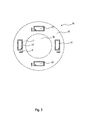
- FIG. 3 an embodiment of the position encoder unit 30 is shown.
- the position encoder unit 30 is provided with, for example, a rotating element (cf. FIGS. 4 and 5 ) and changes their relative position to the receiving coils 40a, 40b by the movement of the rotating element.
- the position encoder unit 30 has a carrier body 31, which may be designed, for example, as a printed circuit board.
- the carrier body 31 is annular. In the middle of the support body 31 has a recess 32 through which the rotating element is feasible.
- the resonant circuits are electromagnetic resonant circuits LC with a capacitor C and a current conductor L as an inductive element.
- the resonant circuit LC can be produced by printed on a printed circuit board tracks. It is preferably a passive resonant circuit LC, which has its own natural frequency. The natural frequencies of the resonant circuits may differ from each other.
- the natural frequency of the resonant circuit LC is the frequency of the exciter field or the AC voltage f.
- the oscillating circuits LC are arranged uniformly spaced around the center of the carrier body. In FIG.
- the resonant circuits do not necessarily have to be arranged within a circle segment or quadrangular. It is also conceivable to provide resonant circuits extending along the circumference of the carrier body, similar to the exciter coil. Furthermore, it is also conceivable to provide a resonant circuit extending around the full circle circumference, wherein the resonant circuits are arranged in different radii.
- the starting and end points of the resonant circuits may have, wherein the starting and end points of the resonant circuits are offset from each other, for example, along the circular path angularly offset.
- each oscillating circuit such that the natural frequency of the oscillating circuits LC differ from each other.
- each resonant circuit can be uniquely identified by means of the natural frequencies, so that it is possible to clearly determine the position of a resonant circuit relative to the measuring fields.
- the frequency of the alternating voltage U ⁇ alternately, for example. Set sequentially in the order of the natural frequencies of the oscillating circuits LC.
- the natural frequency can be set as a function of the differently adjustable AC voltage f.
- the evaluation unit 4 is connected to the receiving coils 40a, 40b and evaluates the output voltages Uout1, Uout2 of the receiving coils 40a, 40b.
- the output voltages Uout1, Uout2 of the receiving coils 40a, 40b are processed by means of demodulators 10.
- the output voltage is usually a sinusoidal or cosinusoidal voltage waveform.
- the amplitude and frequency of the output voltages are excluded by the at least relative angular position of the position encoder unit 30 or of the rotating element.
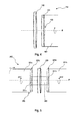
- FIG. 4 schematically shows the structure of a rotation angle sensor 102.
- FIG. 5 the structure of a torque sensor 202 is shown schematically.
- These structures may, for example, with a circuit arrangement 1, as in FIG. 1 shown used. Details of the excitation coil, the receiving coils and the position encoder unit are in the FIGS. 4 and 5 not shown.
- the aforementioned embodiments can be used with these structures.
- the rotation angle sensor 102 off FIG. 4 shows a carrier body 129, on which an excitation coil and two receiving coils are arranged, for example as in FIG. 2 shown.
- the carrier body 129 is attached to a bracket rotatably.
- Adjacent to the carrier body of the excitation coil and the receiving coils is the carrier body 131 of the position encoder unit 130.
- the position encoder unit is mounted on a shaft 180 and rotates with the shaft about the central axis M. This is indicated by the rotating arrow about the central axis M.
- On the outside of the carrier body 131 of the position encoder unit 130 are a plurality of resonant circuits, as in the embodiment of FIG.
- the carrier body 131 of the position encoder unit 130 sits on the end face of the shaft 180.
- the torque sensor 2 has a torsion element 280.
- the torsion element 280 has a first portion 281 a and a second portion 281 b, which are interconnected via a center piece 282.
- the middle piece acts as a kind of torsion spring, so that in the case of an externally applied torque T at one of the sections 281a, 281b, the two sections are rotated relative to each other in torsion angles phi1, phi2 of different magnitudes. Due to the different angles of rotation or torsion angles phi1, phi2 of the first and the second section and the torsional rigidity of the center piece 282, a conclusion on the external torque T can be closed.
- the middle piece 282 passes through a carrier body 229 carrying the excitation coil and the receiving coils (represented by the dashed lines), so that this carrier body 229 is non-rotatably arranged relative to the two portions 281a, 281b of the torsion element 280.
- the position encoder units 230a, 230b each have a carrier body 231a, 231b with recesses through which the center piece 282 is passed to be connected to the respective sections 281a, 281b.
- an encoder unit 230a, 230b which cooperate with the exciter coil and the receiver coils, is arranged on the end faces of the sections 281a, 281b. It may, for example, an encoder unit FIG. 3 be used.
- the coils are arranged on a carrier body 229, which can be arranged between the position transmitter units 230a, 230b. There are two variants of the design possible at this point.
- each position encoder unit 230a, 230b would be associated with an exciter coil and a receiver coil which would be arranged on the opposite side of the carrier body.
- the advantage would be that the position of the position encoder units 230a, 230b could be detected at any time.
- the magnetic influence of the exciter coils on each other and on the receiver coils could lead to a falsification of the measurement results, in particular if the carrier body 229 has a small thickness. This could be prevented by means of a magnetically insulating layer between the respective coil units.
- the disadvantage lies in the fact that the production costs for such a carrier body would be higher.
- the invention is not limited to the aforementioned embodiments.
- the carrier body may be formed, for example, in different shapes. Particularly advantageous are printed circuit boards or films, to which a conductor track can be attached.
- the embodiments can be realized in a simple embodiment with an alternating voltage in one frequency.
- the rotation angle sensor It is also possible to use the rotation angle sensor with a simple circuit arrangement operated at a single AC frequency.
- the evaluation unit 4 is not limited to the above-mentioned embodiment, but can be supplemented by further evaluation electronics.
Landscapes
- Physics & Mathematics (AREA)
- General Physics & Mathematics (AREA)
- Transmission And Conversion Of Sensor Element Output (AREA)
Applications Claiming Priority (1)
| Application Number | Priority Date | Filing Date | Title |
|---|---|---|---|
| DE102013225921.2A DE102013225921A1 (de) | 2013-12-13 | 2013-12-13 | Induktiver Drehwinkel- und Drehmomentsensor mit einer mit Schwingkreisen bestückten Positionsgebereinheit |
Publications (1)
| Publication Number | Publication Date |
|---|---|
| EP2884236A1 true EP2884236A1 (fr) | 2015-06-17 |
Family
ID=52101144
Family Applications (1)
| Application Number | Title | Priority Date | Filing Date |
|---|---|---|---|
| EP14197720.7A Ceased EP2884236A1 (fr) | 2013-12-13 | 2014-12-12 | Capteur inductif de couple et d'angle de rotation doté d'une unité d'indication de position à circuit oscillant |
Country Status (2)
| Country | Link |
|---|---|
| EP (1) | EP2884236A1 (fr) |
| DE (1) | DE102013225921A1 (fr) |
Cited By (5)
| Publication number | Priority date | Publication date | Assignee | Title |
|---|---|---|---|---|
| CN109383620A (zh) * | 2017-08-14 | 2019-02-26 | 丹佛斯动力系统有限公司 | 液压转向装置 |
| CN109952492A (zh) * | 2016-09-09 | 2019-06-28 | 罗伯特·博世有限公司 | 旋转角传感器以及用于旋转角传感器的定子元件 |
| CN111819529A (zh) * | 2018-05-02 | 2020-10-23 | 普瑞有限公司 | 用于测定位置信息的具有操作部件和电磁交变场影响的输入设备 |
| CN113672130A (zh) * | 2021-08-24 | 2021-11-19 | 维沃移动通信有限公司 | 快捷操作方法、装置、电子设备及存储介质 |
| EP4151954A1 (fr) * | 2021-09-17 | 2023-03-22 | Scania CV AB | Agencement de capteur pour déterminer une position angulaire d'un arbre dans un véhicule |
Families Citing this family (5)
| Publication number | Priority date | Publication date | Assignee | Title |
|---|---|---|---|---|
| DE102014212971A1 (de) | 2014-07-03 | 2016-01-07 | Continental Teves Ag & Co. Ohg | Winkelgebereinheit für einen induktiven Winkelsensor mit einen Referenzschwingkreis |
| DE102016100260A1 (de) * | 2016-01-08 | 2017-07-13 | Turck Holding Gmbh | Wegsensor mit mehreren hintereinander legbaren Wegaufnehmern |
| DE102018213249A1 (de) | 2018-08-07 | 2020-02-13 | Robert Bosch Gmbh | Sensorsystem zur Bestimmung mindestens einer Rotationseigenschaft eines rotierenden Elements |
| DE102020110666A1 (de) | 2020-04-20 | 2021-10-21 | Schaeffler Technologies AG & Co. KG | Sensoranordnung zur Erfassung eines Drehmoments und einer Winkelstellung |
| DE102020212557A1 (de) | 2020-10-05 | 2022-04-07 | Thyssenkrupp Ag | Sensorvorrichtung zur Erfassung eines Drehwinkels |
Citations (6)
| Publication number | Priority date | Publication date | Assignee | Title |
|---|---|---|---|---|
| US2384789A (en) * | 1941-02-13 | 1945-09-18 | Radio Patents Corp | Frequency modulator |
| DE3832152A1 (de) * | 1988-09-22 | 1990-03-29 | Philips Patentverwaltung | Digitaler frequenzgenerator |
| EP1666836A2 (fr) * | 2004-11-19 | 2006-06-07 | AB Elektronik GmbH | Capteur de couple et capteur de rotation |
| EP1925914A2 (fr) * | 2006-11-22 | 2008-05-28 | AB Elektronik GmbH | Capteur inductif destiné à la saisie de deux éléments de couplage |
| EP1828722B1 (fr) | 2004-12-20 | 2011-11-02 | Howard, Mark Anthony | Capteur de position inductive |
| GB2493399A (en) * | 2011-08-05 | 2013-02-06 | Tt Electronics Technology Ltd | Inductive position sensor with multiple resonant circuits of differing resonant frequencies |
Family Cites Families (3)
| Publication number | Priority date | Publication date | Assignee | Title |
|---|---|---|---|---|
| GB2394293A (en) * | 2002-10-16 | 2004-04-21 | Gentech Invest Group Ag | Inductive sensing apparatus and method |
| WO2009118042A1 (fr) * | 2008-03-26 | 2009-10-01 | Elmos Semiconductor Ag | Capteur de position inductif |
| DE202008008477U1 (de) * | 2007-06-27 | 2008-10-09 | Ab Elektronik Gmbh | Stabförmiger Linearsensor |
-
2013
- 2013-12-13 DE DE102013225921.2A patent/DE102013225921A1/de not_active Withdrawn
-
2014
- 2014-12-12 EP EP14197720.7A patent/EP2884236A1/fr not_active Ceased
Patent Citations (6)
| Publication number | Priority date | Publication date | Assignee | Title |
|---|---|---|---|---|
| US2384789A (en) * | 1941-02-13 | 1945-09-18 | Radio Patents Corp | Frequency modulator |
| DE3832152A1 (de) * | 1988-09-22 | 1990-03-29 | Philips Patentverwaltung | Digitaler frequenzgenerator |
| EP1666836A2 (fr) * | 2004-11-19 | 2006-06-07 | AB Elektronik GmbH | Capteur de couple et capteur de rotation |
| EP1828722B1 (fr) | 2004-12-20 | 2011-11-02 | Howard, Mark Anthony | Capteur de position inductive |
| EP1925914A2 (fr) * | 2006-11-22 | 2008-05-28 | AB Elektronik GmbH | Capteur inductif destiné à la saisie de deux éléments de couplage |
| GB2493399A (en) * | 2011-08-05 | 2013-02-06 | Tt Electronics Technology Ltd | Inductive position sensor with multiple resonant circuits of differing resonant frequencies |
Cited By (13)
| Publication number | Priority date | Publication date | Assignee | Title |
|---|---|---|---|---|
| CN109952492B (zh) * | 2016-09-09 | 2021-07-20 | 罗伯特·博世有限公司 | 旋转角传感器以及用于旋转角传感器的定子元件 |
| CN109952492A (zh) * | 2016-09-09 | 2019-06-28 | 罗伯特·博世有限公司 | 旋转角传感器以及用于旋转角传感器的定子元件 |
| US20190242726A1 (en) * | 2016-09-09 | 2019-08-08 | Robert Bosch Gmbh | Rotary Sensor and Stator Element for Same |
| US10955262B2 (en) | 2016-09-09 | 2021-03-23 | Robert Bosch Gmbh | Rotation angle sensor for a stator |
| CN109383620A (zh) * | 2017-08-14 | 2019-02-26 | 丹佛斯动力系统有限公司 | 液压转向装置 |
| US10862382B2 (en) | 2017-08-14 | 2020-12-08 | Danfoss Power Solutions Aps | Hydraulic steering arrangement |
| CN109383620B (zh) * | 2017-08-14 | 2021-04-20 | 丹佛斯动力系统有限公司 | 液压转向装置 |
| CN111819529A (zh) * | 2018-05-02 | 2020-10-23 | 普瑞有限公司 | 用于测定位置信息的具有操作部件和电磁交变场影响的输入设备 |
| CN111819529B (zh) * | 2018-05-02 | 2024-06-25 | 普瑞有限公司 | 输入设备及用于运行该输入设备的方法 |
| CN113672130A (zh) * | 2021-08-24 | 2021-11-19 | 维沃移动通信有限公司 | 快捷操作方法、装置、电子设备及存储介质 |
| CN113672130B (zh) * | 2021-08-24 | 2025-01-24 | 维沃移动通信有限公司 | 快捷操作方法、装置、电子设备及存储介质 |
| EP4151954A1 (fr) * | 2021-09-17 | 2023-03-22 | Scania CV AB | Agencement de capteur pour déterminer une position angulaire d'un arbre dans un véhicule |
| WO2023043355A1 (fr) * | 2021-09-17 | 2023-03-23 | Scania Cv Ab | Dispositif de détection pour détermination d'une position angulaire d'un arbre dans un véhicule |
Also Published As
| Publication number | Publication date |
|---|---|
| DE102013225921A1 (de) | 2015-07-02 |
Similar Documents
| Publication | Publication Date | Title |
|---|---|---|
| DE102013225921A1 (de) | Induktiver Drehwinkel- und Drehmomentsensor mit einer mit Schwingkreisen bestückten Positionsgebereinheit | |
| EP3642567B1 (fr) | Capteur d'angle de rotation | |
| EP3420316B1 (fr) | Capteur d'angle de rotation | |
| DE102006026543B4 (de) | Lagegeber und zugehöriges Verfahren zum Erfassen einer Position eines Läufers einer Maschine | |
| EP2105713B1 (fr) | Appareil de mesure de position et son procédé de fonctionnement | |
| EP3645977B1 (fr) | Système de détection pour déterminer au moins une propriété de rotation d'un élément en rotation | |
| EP3029427B1 (fr) | Dispositif et algorithme destines a la determination d'angle mecanique radial absolu d'un arbre | |
| EP2884238A1 (fr) | Capteur d'angle de rotation inductif doté d'une bobine de réception et d'excitation en forme de segment circulaire | |
| EP3555571B1 (fr) | Système de capteur pour déterminer au moins une propriété de rotation d'au moins un élément rotatif tournant autour d'au moins un axe de rotation | |
| DE102017222063A1 (de) | Induktive Positionsmesseinrichtung | |
| EP1906153A2 (fr) | Encodeur et son procédé de fonctionnement | |
| DE102013224098A1 (de) | Sensoranordnung zur Erfassung von Drehwinkeln an einem rotierenden Bauteil in einem Fahrzeug | |
| DE102019127297A1 (de) | Sensorvorrichtung zur Erfassung der Drehwinkelstellung einer drehbeweglichen Welle sowie Lenkungsanordnung eines Fahrzeugs | |
| DE102018213249A1 (de) | Sensorsystem zur Bestimmung mindestens einer Rotationseigenschaft eines rotierenden Elements | |
| EP2834601B1 (fr) | Procédé et ensemble pour déterminer la position d'un composant | |
| WO2017129458A2 (fr) | Machine, en particulier moteur d'entraînement électrique et procédé de transmission de données sans fil entre un rotor et un stator et/ou de détection de la vitesse de rotation du rotor | |
| DE102004026311B4 (de) | Positionsgeber | |
| DE102014218982A1 (de) | Sensoranordnung zur Weg- und/oder Winkelmessung | |
| EP2884237A1 (fr) | Capteur d'angle de rotation inductif | |
| DE102013215320A1 (de) | Vorrichtung zur Erfassung des Drehmomentes in einer Welle | |
| EP2884234A1 (fr) | Capteur inductif ayant une trajectoire de mesure d'une longueur quelconque | |
| EP3975211B1 (fr) | Unification de résolveur et de d'alimentation inductive de rotor dans un cercle magnétique | |
| DE102013225873A1 (de) | Induktiver Sensor auf Basis des Noniusprinzips | |
| DE102018108019B4 (de) | Messanordnung zur Messung einer Drehlage und/oder einer Drehzahl einer Kurbelwelle | |
| DE102016224854A1 (de) | Sensorsystem zur Bestimmung mindestens einer Rotationseigenschaft eines um mindestens eine Rotationsachse rotierenden Elements |
Legal Events
| Date | Code | Title | Description |
|---|---|---|---|
| PUAI | Public reference made under article 153(3) epc to a published international application that has entered the european phase |
Free format text: ORIGINAL CODE: 0009012 |
|
| 17P | Request for examination filed |
Effective date: 20141212 |
|
| AK | Designated contracting states |
Kind code of ref document: A1 Designated state(s): AL AT BE BG CH CY CZ DE DK EE ES FI FR GB GR HR HU IE IS IT LI LT LU LV MC MK MT NL NO PL PT RO RS SE SI SK SM TR |
|
| AX | Request for extension of the european patent |
Extension state: BA ME |
|
| R17P | Request for examination filed (corrected) |
Effective date: 20151217 |
|
| RBV | Designated contracting states (corrected) |
Designated state(s): AL AT BE BG CH CY CZ DE DK EE ES FI FR GB GR HR HU IE IS IT LI LT LU LV MC MK MT NL NO PL PT RO RS SE SI SK SM TR |
|
| 17Q | First examination report despatched |
Effective date: 20180607 |
|
| RAP1 | Party data changed (applicant data changed or rights of an application transferred) |
Owner name: CONTINENTAL TEVES AG & CO. OHG |
|
| STAA | Information on the status of an ep patent application or granted ep patent |
Free format text: STATUS: THE APPLICATION HAS BEEN REFUSED |
|
| 18R | Application refused |
Effective date: 20190118 |