EP2884253A2 - Système et appareil pour inspecter des câbles à fibres optiques - Google Patents
Système et appareil pour inspecter des câbles à fibres optiques Download PDFInfo
- Publication number
- EP2884253A2 EP2884253A2 EP14197815.5A EP14197815A EP2884253A2 EP 2884253 A2 EP2884253 A2 EP 2884253A2 EP 14197815 A EP14197815 A EP 14197815A EP 2884253 A2 EP2884253 A2 EP 2884253A2
- Authority
- EP
- European Patent Office
- Prior art keywords
- fiber optic
- optic cable
- mobile device
- housing
- network interfaces
- Prior art date
- Legal status (The legal status is an assumption and is not a legal conclusion. Google has not performed a legal analysis and makes no representation as to the accuracy of the status listed.)
- Ceased
Links
Images

Classifications
-
- H—ELECTRICITY
- H04—ELECTRIC COMMUNICATION TECHNIQUE
- H04B—TRANSMISSION
- H04B10/00—Transmission systems employing electromagnetic waves other than radio-waves, e.g. infrared, visible or ultraviolet light, or employing corpuscular radiation, e.g. quantum communication
- H04B10/07—Arrangements for monitoring or testing transmission systems; Arrangements for fault measurement of transmission systems
- H04B10/073—Arrangements for monitoring or testing transmission systems; Arrangements for fault measurement of transmission systems using an out-of-service signal
-
- G—PHYSICS
- G01—MEASURING; TESTING
- G01M—TESTING STATIC OR DYNAMIC BALANCE OF MACHINES OR STRUCTURES; TESTING OF STRUCTURES OR APPARATUS, NOT OTHERWISE PROVIDED FOR
- G01M11/00—Testing of optical apparatus; Testing structures by optical methods not otherwise provided for
- G01M11/08—Testing mechanical properties
- G01M11/088—Testing mechanical properties of optical fibres; Mechanical features associated with the optical testing of optical fibres
-
- H—ELECTRICITY
- H04—ELECTRIC COMMUNICATION TECHNIQUE
- H04B—TRANSMISSION
- H04B10/00—Transmission systems employing electromagnetic waves other than radio-waves, e.g. infrared, visible or ultraviolet light, or employing corpuscular radiation, e.g. quantum communication
- H04B10/07—Arrangements for monitoring or testing transmission systems; Arrangements for fault measurement of transmission systems
-
- H—ELECTRICITY
- H04—ELECTRIC COMMUNICATION TECHNIQUE
- H04B—TRANSMISSION
- H04B10/00—Transmission systems employing electromagnetic waves other than radio-waves, e.g. infrared, visible or ultraviolet light, or employing corpuscular radiation, e.g. quantum communication
- H04B10/25—Arrangements specific to fibre transmission
-
- G—PHYSICS
- G01—MEASURING; TESTING
- G01N—INVESTIGATING OR ANALYSING MATERIALS BY DETERMINING THEIR CHEMICAL OR PHYSICAL PROPERTIES
- G01N21/00—Investigating or analysing materials by the use of optical means, i.e. using sub-millimetre waves, infrared, visible or ultraviolet light
- G01N21/84—Systems specially adapted for particular applications
- G01N21/88—Investigating the presence of flaws or contamination
- G01N21/95—Investigating the presence of flaws or contamination characterised by the material or shape of the object to be examined
- G01N21/952—Inspecting the exterior surface of cylindrical bodies or wires
-
- G—PHYSICS
- G02—OPTICS
- G02B—OPTICAL ELEMENTS, SYSTEMS OR APPARATUS
- G02B6/00—Light guides; Structural details of arrangements comprising light guides and other optical elements, e.g. couplings
- G02B6/24—Coupling light guides
- G02B6/26—Optical coupling means
- G02B6/32—Optical coupling means having lens focusing means positioned between opposed fibre ends
-
- G—PHYSICS
- G02—OPTICS
- G02B—OPTICAL ELEMENTS, SYSTEMS OR APPARATUS
- G02B6/00—Light guides; Structural details of arrangements comprising light guides and other optical elements, e.g. couplings
- G02B6/24—Coupling light guides
- G02B6/42—Coupling light guides with opto-electronic elements
- G02B6/4201—Packages, e.g. shape, construction, internal or external details
- G02B6/4219—Mechanical fixtures for holding or positioning the elements relative to each other in the couplings; Alignment methods for the elements, e.g. measuring or observing methods especially used therefor
- G02B6/422—Active alignment, i.e. moving the elements in response to the detected degree of coupling or position of the elements
- G02B6/4226—Positioning means for moving the elements into alignment, e.g. alignment screws, deformation of the mount
-
- G—PHYSICS
- G02—OPTICS
- G02B—OPTICAL ELEMENTS, SYSTEMS OR APPARATUS
- G02B6/00—Light guides; Structural details of arrangements comprising light guides and other optical elements, e.g. couplings
- G02B6/24—Coupling light guides
- G02B6/42—Coupling light guides with opto-electronic elements
- G02B6/4292—Coupling light guides with opto-electronic elements the light guide being disconnectable from the opto-electronic element, e.g. mutually self aligning arrangements
Definitions
- the present disclosure relates to network testing equipment, and more particularly to fiber optic network testing equipment.
- Fiber optic cable possesses numerous advantages over conventional coaxial electrical cable and other hardwired data transmission mediums. For example, because fiber optic cable carries no electricity, fiber optic systems are often more reliable and insensitive to cable damage than hardwire systems. In addition, fiber optic cable uses light for data transmission thereby supporting an increase in bandwidth.
- testing fiber optic cables requires expensive and dedicated testing equipment (e.g., handheld network testers with a microscope and a digital camera, computers, etc.).
- dedicated testing equipment typically involves complex electronics, which directly corresponds to an increase in cost.
- the fiber optic test apparatus of the present disclosure converts such mobile devices into fiber optic testing devices.
- the fiber optic test apparatus includes a housing that is mounted to various models of mobile devices as well as a magnification lens, and a network interface (e.g., a terminal connector that mates with a fiber optic terminal connector).
- the apparatus is typically used in conjunction with an application resident on the mobile device, which displays an image of the fiber optic (e.g., taken by the mobile device's camera and light source).
- the fiber optic test apparatus couples to a user's mobile device and assists the mobile device in image processing the fiber optic cable. Once an image is taken by the mobile device, it is analyzed the image of the fiber optic connector end-surface impurities or imperfections and displayed the image and the results (pass/fail) to a user.
- the fiber optic test apparatus includes a housing configured and adapted to couple to a mobile device and one or more network interfaces in communication with the housing.
- the one or more network interfaces are configured and adapted to operatively couple to a terminal end of a fiber optic cable.
- the apparatus also includes a magnification lens in operative communication with the housing and the one or more network interfaces.
- the apparatus can further include a tuning knob in communication with the magnification lens, which adjusts a focal point of the magnification lens.
- the apparatus further includes one or more extension cables configured to couple to the one or more network interfaces.
- the one or more network interfaces operatively receive the terminal end of the fiber optic cable via the extension cable(s).
- Certain mobile devices also include a resident light source (e.g., an LED).
- a resident light source e.g., an LED
- the housing of the apparatus is configured and adapted to accommodate such resident light source of the mobile device thereby causing the resident light source to provide illumination to the fiber optic cable during testing procedures (e.g., when the camera is imaging the fiber optic cable).
- the apparatus includes a light source.
- certain embodiments include an integrated case or molding (e.g., a mobile phone case, etc.) that couples to the mobile device.
- the housing is configured and adapted to couple to the mobile device via two opposed rails that attach or clip to corresponding opposed sides of the mobile device.
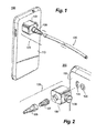
- FIG. 1 a partial view of an exemplary embodiment of the fiber optic cable inspection apparatus in accordance with the invention is shown in FIG. 1 and is designated generally by reference character 105.
- FIGS. 2-8 Other embodiments of the fiber optic cable inspection apparatus in accordance with this disclosure, or aspects thereof, are provided in FIGS. 2-8 , as will be described.
- the fiber optic cable inspection apparatus can be used for example to inspect terminal ends of fiber optic cables using a mobile device (e.g., a mobile phone, a tablet, a laptop, a computer, and the like).
- a mobile device e.g., a mobile phone, a tablet, a laptop, a computer, and the like.
- FIG. 1 a perspective view 100 of fiber optic cable inspection apparatus 105 is shown.
- Perspective view 100 particularly illustrates fiber optic cable inspection apparatus 105 coupled to a mobile device 110 (shown as a mobile phone) via a housing 106.
- a mobile device 110 shown as a mobile phone
- housing 106 can readily be configured to couple to any number of devices such as, but not limited to laptops, tablets, computers, etc.
- fiber optic cable inspection apparatus 105 receives or couples to a corresponding fiber optic cable 130.
- fiber optic cable inspection apparatus 105 also includes a network interface 108 (e.g., a terminal adapter) configured and adapted to operatively receive (e.g., couple with) a terminal end of a fiber optic cable (not shown).
- network interface 108 e.g., a terminal adapter
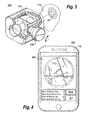
- FIG. 2 there is shown an exploded perspective view 200 of the fiber optic inspection apparatus 105.
- Exploded perspective view 200 illustrates various components of the fiber optic inspection apparatus 105, including housing 106, network interface 108 and an optical lens 107, which preferably is situated intermediate to housing 106 and network interface 108.
- Optical lens 107 is preferably a microscope lens that operatively provides magnified views of a fiber optic cable when lens is coupled or attached to network interface 108, as discussed below.
- housing 106 also preferably includes an adjustment knob 109 that changes a focal length of optical lens 107.
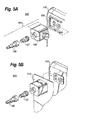
- FIG. 3 a partial cut-away view 300 of housing 106 showing the operation of an adjustment feature (i.e., knob 109), which functions to move or adjust optical lens 107.
- an adjustment feature i.e., knob 109
- Fiber optic inspection apparatus 105 couples or attaches to mobile device 110.
- Fiber optic inspection apparatus 105 preferably couples to a resident light source (e.g., Light Emitting Diode (LED) 115) and resident camera 120 on mobile device 110.
- a resident light source e.g., Light Emitting Diode (LED) 115
- a user of mobile device 110 uses a locally running application (that uses, for example, camera 120 and/or LED 115) and analyzes images from optic inspection apparatus 105 to determine a state of the attached fiber optic cable.
- the light source maybe independently provided (e.g., not resident on mobile device 110).
- the light source can be incorporated within housing 106.
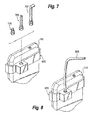
- FIG. 4 provides a display screen 405 of the mobile device 110, showing a status of a fiber optic cable attached to fiber optic inspection apparatus 105 (not shown).
- a status of the fiber optic cable can include a number of blobs and scratches in a core or a clad.
- the user analyzes the status of the fiber optic cable and indicates or selects "FAIL" or "GO" (e.g., pass, etc.).
- the application running on mobile device 110 can save the selection, transmit the data to one or more additional users, devices, etc., and/or take subsequent corrective action (if necessary).
- FIGS. 5A-5B illustrate two other embodiments of the fiber optic inspection apparatus.
- FIG. 5A provides an exploded perspective view 500 of the fiber optic inspection apparatus configured to couple to mobile device 110 via molding 505.
- Molding 505 can be integrated into mobile device 110 by, for example, incorporating molding during manufacture of mobile device 110 or adding molding post manufacture via an adhesive, etc., and the like.
- fiber optic inspection apparatus 105 couples molding 505 thereby attaching to mobile device 110.
- FIG. 5B illustrates an exploded perspective view of the fiber optic inspection apparatus configured as a mobile phone case 510 that couples mobile device 110.
- housing 106 is formed integral with mobile phone case 510.
- mobile phone case 510 and housing 106 can be coupled by other known means (e.g., a snap closure, adhesive, etc.).
- FIGS. 6-8 are perspective views of a fiber optic inspection apparatus 605 configured as a clip on adapter that couples to mobile device 110.
- fiber optic inspection apparatus 605 includes a pair of opposed rails or arms that clip to corresponding opposed sides of mobile device 110.
- the fiber optic inspection apparatus 605 operatively couples to the resident camera and light source (e.g., an LED) of mobile device 110.
- FIG. 7 shows the fiber optic inspection apparatus 605 attached to mobile device 110 as well as additional extension adapters 705 that can be interchangeable used in conjunction with clip 605.
- the extension adapters can fit various types of fiber optic terminal ends and/or be of varying lengths depending on a location of the fiber optic terminal.
- FIG. 8 is a perspective view of the fiber optic inspection apparatus illustrated in FIG. 7 , showing an extension adapter 805 coupled to fiber optic inspection apparatus 605. As shown, extension can have a threaded design that mates with a corresponding threading of fiber optic inspection apparatus 605.
- the techniques described herein therefore, provide for an improved network test apparatus that adapts a mobile device for network testing purposes (e.g., testing fiber optic cables or wires).
- the techniques herein provide a low cost and easy to manufacture apparatus that leverages resident electronics (e.g., processors, displays, cameras, light sources, etc.) of mobile devices. In this fashion, a network tester does not need to bring dedicated testing equipment that can be both burdensome to travel with as well as expensive to maintain.
Landscapes
- Physics & Mathematics (AREA)
- Electromagnetism (AREA)
- Engineering & Computer Science (AREA)
- Computer Networks & Wireless Communication (AREA)
- Signal Processing (AREA)
- Chemical & Material Sciences (AREA)
- Analytical Chemistry (AREA)
- General Physics & Mathematics (AREA)
- Investigating Materials By The Use Of Optical Means Adapted For Particular Applications (AREA)
- Optical Couplings Of Light Guides (AREA)
- Light Guides In General And Applications Therefor (AREA)
Applications Claiming Priority (1)
| Application Number | Priority Date | Filing Date | Title |
|---|---|---|---|
| US14/107,898 US9634759B2 (en) | 2013-12-16 | 2013-12-16 | System and apparatus for inspecting fiber optic cables |
Publications (2)
| Publication Number | Publication Date |
|---|---|
| EP2884253A2 true EP2884253A2 (fr) | 2015-06-17 |
| EP2884253A3 EP2884253A3 (fr) | 2015-07-08 |
Family
ID=52146125
Family Applications (1)
| Application Number | Title | Priority Date | Filing Date |
|---|---|---|---|
| EP14197815.5A Ceased EP2884253A3 (fr) | 2013-12-16 | 2014-12-12 | Système et appareil pour inspecter des câbles à fibres optiques |
Country Status (4)
| Country | Link |
|---|---|
| US (1) | US9634759B2 (fr) |
| EP (1) | EP2884253A3 (fr) |
| CN (1) | CN104713698A (fr) |
| AU (1) | AU2014277661A1 (fr) |
Families Citing this family (6)
| Publication number | Priority date | Publication date | Assignee | Title |
|---|---|---|---|---|
| SE540543C2 (en) * | 2015-03-03 | 2018-09-25 | Roxtec Ab | An inspection system for cable, pipe or wire transits |
| CN105652396B (zh) * | 2016-03-31 | 2017-09-22 | 中航光电科技股份有限公司 | 一种用于光纤检测的装置及使用该装置的光纤检测设备 |
| JP7187072B2 (ja) * | 2017-05-10 | 2022-12-12 | 株式会社Okファイバーテクノロジー | ファイバースコープ接続具、及びファイバースコープシステム |
| JP7040729B2 (ja) * | 2017-05-10 | 2022-03-23 | 株式会社Okファイバーテクノロジー | ファイバースコープ接続具、及びファイバースコープシステム |
| US11385412B2 (en) * | 2020-05-26 | 2022-07-12 | Westek Electronics, Inc. | Fiber inspection tool |
| WO2025003762A1 (fr) * | 2023-06-27 | 2025-01-02 | Belden Canada Ulc | Dispositif d'inspection configuré pour fournir une inspection améliorée d'un ordre de couleur de fibre dans un câble à fibres optiques nervuré |
Citations (1)
| Publication number | Priority date | Publication date | Assignee | Title |
|---|---|---|---|---|
| US20030174875A1 (en) * | 2002-03-18 | 2003-09-18 | Mike Buzzetti | Automated fiber optic inspection system |
Family Cites Families (8)
| Publication number | Priority date | Publication date | Assignee | Title |
|---|---|---|---|---|
| AU2001281363A1 (en) * | 2000-08-01 | 2002-02-13 | Wavecrest Corporation | Electromagnetic and optical analyzer |
| CN200972426Y (zh) * | 2006-09-29 | 2007-11-07 | 崔旭 | 一种光纤端面检测仪 |
| CN201116939Y (zh) * | 2007-07-20 | 2008-09-17 | 周其 | 光纤端面检查装置 |
| US9217688B2 (en) * | 2009-10-08 | 2015-12-22 | Piotr Anatolij Levin | Fiber optic end face inspection probe and system |
| EP2633678A4 (fr) | 2010-10-29 | 2015-05-20 | Univ California | Appareil de type téléphone microscope ou cellscope et procédés d'imagerie |
| US9733616B2 (en) | 2011-12-28 | 2017-08-15 | Exfo Inc. | Portable digital holographic probe for the inspection of optical fiber connectors, and inspection system and method for the same |
| US9841579B2 (en) * | 2013-09-27 | 2017-12-12 | Exfo Inc. | Multiple-fiber connector inspection |
| US20150116700A1 (en) * | 2013-10-31 | 2015-04-30 | Corning Cable Systems Llc | Device for inspecting a cleave of an optical fiber endface, and related components, systems and methods |
-
2013
- 2013-12-16 US US14/107,898 patent/US9634759B2/en not_active Expired - Fee Related
-
2014
- 2014-12-12 EP EP14197815.5A patent/EP2884253A3/fr not_active Ceased
- 2014-12-15 CN CN201410858322.XA patent/CN104713698A/zh active Pending
- 2014-12-15 AU AU2014277661A patent/AU2014277661A1/en not_active Abandoned
Patent Citations (1)
| Publication number | Priority date | Publication date | Assignee | Title |
|---|---|---|---|---|
| US20030174875A1 (en) * | 2002-03-18 | 2003-09-18 | Mike Buzzetti | Automated fiber optic inspection system |
Also Published As
| Publication number | Publication date |
|---|---|
| CN104713698A (zh) | 2015-06-17 |
| US9634759B2 (en) | 2017-04-25 |
| EP2884253A3 (fr) | 2015-07-08 |
| AU2014277661A1 (en) | 2015-07-02 |
| US20150171959A1 (en) | 2015-06-18 |
Similar Documents
| Publication | Publication Date | Title |
|---|---|---|
| US9634759B2 (en) | System and apparatus for inspecting fiber optic cables | |
| US20150054935A1 (en) | Portable terminal adaptor for microscope, and microscopic imaging method using the portable terminal adaptor | |
| KR20160098215A (ko) | 홈 테스팅 장치 | |
| US9417444B2 (en) | User-friendly wireless fiber optic endface inspector | |
| CN105264435A (zh) | 显微镜观测筒智能手机适配器 | |
| EP3304024A1 (fr) | Réflectomètre optique à domaine temporel (otdr), conjointement avec câble de lancement rétractable intégré | |
| US20200082521A1 (en) | Display apparatus and method for optical fiber inspection | |
| CN205484071U (zh) | 一种试纸检测装置 | |
| US20150116700A1 (en) | Device for inspecting a cleave of an optical fiber endface, and related components, systems and methods | |
| US20150116699A1 (en) | Removable device for inspecting polish of an optical fiber endface using a portable camera, and related components, systems, and methods | |
| US12566300B2 (en) | Ferrule profile imaging and measurement | |
| US10515745B2 (en) | Medical coaxial connector, medical coaxial cable, and medical observation system | |
| CN109348010A (zh) | 一种全面屏移动终端 | |
| CN106840005A (zh) | 一种架空导线线径非接触测定方法及线缆标准板 | |
| US20250305908A1 (en) | Changeable tip for optical fiber inspection device with detectable tip orientation | |
| US20190383698A1 (en) | Automatic analysis of a set of optical fibers of an optical cable | |
| CN113824938A (zh) | 投影控制方法、装置、终端及存储介质 | |
| US20170363855A1 (en) | Modular camera attachment for optical devices | |
| EP3156780B1 (fr) | Sonde de test pour inspection rationnelle | |
| US12591128B2 (en) | Magnifying lamp with camera | |
| KR20160008263A (ko) | 모바일 폰을 이용한 현미경이미지 장치 | |
| CN204049610U (zh) | 裂隙灯的成像显示装置 | |
| KR20150011698A (ko) | 투과율 측정 장치 | |
| CN106324298A (zh) | 一种点灯测试设备 | |
| KR20080078090A (ko) | 휴대형 유에스비 현미경 및 그를 이용한 측정 방법 |
Legal Events
| Date | Code | Title | Description |
|---|---|---|---|
| PUAL | Search report despatched |
Free format text: ORIGINAL CODE: 0009013 |
|
| PUAI | Public reference made under article 153(3) epc to a published international application that has entered the european phase |
Free format text: ORIGINAL CODE: 0009012 |
|
| 17P | Request for examination filed |
Effective date: 20141212 |
|
| AK | Designated contracting states |
Kind code of ref document: A2 Designated state(s): AL AT BE BG CH CY CZ DE DK EE ES FI FR GB GR HR HU IE IS IT LI LT LU LV MC MK MT NL NO PL PT RO RS SE SI SK SM TR |
|
| AX | Request for extension of the european patent |
Extension state: BA ME |
|
| AK | Designated contracting states |
Kind code of ref document: A3 Designated state(s): AL AT BE BG CH CY CZ DE DK EE ES FI FR GB GR HR HU IE IS IT LI LT LU LV MC MK MT NL NO PL PT RO RS SE SI SK SM TR |
|
| AX | Request for extension of the european patent |
Extension state: BA ME |
|
| RIC1 | Information provided on ipc code assigned before grant |
Ipc: G02B 6/00 20060101ALI20150604BHEP Ipc: G01M 11/08 20060101AFI20150604BHEP Ipc: G01N 21/952 20060101ALI20150604BHEP |
|
| 17Q | First examination report despatched |
Effective date: 20171207 |
|
| STAA | Information on the status of an ep patent application or granted ep patent |
Free format text: STATUS: THE APPLICATION HAS BEEN REFUSED |
|
| 18R | Application refused |
Effective date: 20191123 |