EP2884342A2 - Bilderzeugungsvorrichtung, Bilderzeugungssystem und Verfahren zur Steuerung davon - Google Patents
Bilderzeugungsvorrichtung, Bilderzeugungssystem und Verfahren zur Steuerung davon Download PDFInfo
- Publication number
- EP2884342A2 EP2884342A2 EP14198149.8A EP14198149A EP2884342A2 EP 2884342 A2 EP2884342 A2 EP 2884342A2 EP 14198149 A EP14198149 A EP 14198149A EP 2884342 A2 EP2884342 A2 EP 2884342A2
- Authority
- EP
- European Patent Office
- Prior art keywords
- paper sheet
- section
- jam
- abnormal state
- conveying
- Prior art date
- Legal status (The legal status is an assumption and is not a legal conclusion. Google has not performed a legal analysis and makes no representation as to the accuracy of the status listed.)
- Granted
Links
Images



Classifications
-
- B—PERFORMING OPERATIONS; TRANSPORTING
- B65—CONVEYING; PACKING; STORING; HANDLING THIN OR FILAMENTARY MATERIAL
- B65H—HANDLING THIN OR FILAMENTARY MATERIAL, e.g. SHEETS, WEBS, CABLES
- B65H29/00—Delivering or advancing articles from machines; Advancing articles to or into piles
- B65H29/58—Article switches or diverters
- B65H29/60—Article switches or diverters diverting the stream into alternative paths
-
- B—PERFORMING OPERATIONS; TRANSPORTING
- B65—CONVEYING; PACKING; STORING; HANDLING THIN OR FILAMENTARY MATERIAL
- B65H—HANDLING THIN OR FILAMENTARY MATERIAL, e.g. SHEETS, WEBS, CABLES
- B65H31/00—Pile receivers
- B65H31/24—Pile receivers multiple or compartmented, e.d. for alternate, programmed, or selective filling
-
- B—PERFORMING OPERATIONS; TRANSPORTING
- B65—CONVEYING; PACKING; STORING; HANDLING THIN OR FILAMENTARY MATERIAL
- B65H—HANDLING THIN OR FILAMENTARY MATERIAL, e.g. SHEETS, WEBS, CABLES
- B65H43/00—Use of control, checking, or safety devices, e.g. automatic devices comprising an element for sensing a variable
-
- G—PHYSICS
- G03—PHOTOGRAPHY; CINEMATOGRAPHY; ANALOGOUS TECHNIQUES USING WAVES OTHER THAN OPTICAL WAVES; ELECTROGRAPHY; HOLOGRAPHY
- G03G—ELECTROGRAPHY; ELECTROPHOTOGRAPHY; MAGNETOGRAPHY
- G03G15/00—Apparatus for electrographic processes using a charge pattern
- G03G15/55—Self-diagnostics; Malfunction or lifetime display
-
- G—PHYSICS
- G03—PHOTOGRAPHY; CINEMATOGRAPHY; ANALOGOUS TECHNIQUES USING WAVES OTHER THAN OPTICAL WAVES; ELECTROGRAPHY; HOLOGRAPHY
- G03G—ELECTROGRAPHY; ELECTROPHOTOGRAPHY; MAGNETOGRAPHY
- G03G15/00—Apparatus for electrographic processes using a charge pattern
- G03G15/70—Detecting malfunctions relating to paper handling, e.g. jams
-
- B—PERFORMING OPERATIONS; TRANSPORTING
- B65—CONVEYING; PACKING; STORING; HANDLING THIN OR FILAMENTARY MATERIAL
- B65H—HANDLING THIN OR FILAMENTARY MATERIAL, e.g. SHEETS, WEBS, CABLES
- B65H2511/00—Dimensions; Position; Numbers; Identification; Occurrences
- B65H2511/50—Occurence
- B65H2511/52—Defective operating conditions
- B65H2511/528—Jam
-
- B—PERFORMING OPERATIONS; TRANSPORTING
- B65—CONVEYING; PACKING; STORING; HANDLING THIN OR FILAMENTARY MATERIAL
- B65H—HANDLING THIN OR FILAMENTARY MATERIAL, e.g. SHEETS, WEBS, CABLES
- B65H2513/00—Dynamic entities; Timing aspects
- B65H2513/40—Movement
- B65H2513/42—Route, path
-
- G—PHYSICS
- G03—PHOTOGRAPHY; CINEMATOGRAPHY; ANALOGOUS TECHNIQUES USING WAVES OTHER THAN OPTICAL WAVES; ELECTROGRAPHY; HOLOGRAPHY
- G03G—ELECTROGRAPHY; ELECTROPHOTOGRAPHY; MAGNETOGRAPHY
- G03G15/00—Apparatus for electrographic processes using a charge pattern
- G03G15/50—Machine control of apparatus for electrographic processes using a charge pattern, e.g. regulating differents parts of the machine, multimode copiers, microprocessor control
- G03G15/5012—Priority interrupt; Job recovery, e.g. after jamming or malfunction
-
- G—PHYSICS
- G03—PHOTOGRAPHY; CINEMATOGRAPHY; ANALOGOUS TECHNIQUES USING WAVES OTHER THAN OPTICAL WAVES; ELECTROGRAPHY; HOLOGRAPHY
- G03G—ELECTROGRAPHY; ELECTROPHOTOGRAPHY; MAGNETOGRAPHY
- G03G2215/00—Apparatus for electrophotographic processes
- G03G2215/00362—Apparatus for electrophotographic processes relating to the copy medium handling
- G03G2215/00535—Stable handling of copy medium
- G03G2215/00548—Jam, error detection, e.g. double feeding
-
- G—PHYSICS
- G03—PHOTOGRAPHY; CINEMATOGRAPHY; ANALOGOUS TECHNIQUES USING WAVES OTHER THAN OPTICAL WAVES; ELECTROGRAPHY; HOLOGRAPHY
- G03G—ELECTROGRAPHY; ELECTROPHOTOGRAPHY; MAGNETOGRAPHY
- G03G2215/00—Apparatus for electrophotographic processes
- G03G2215/00362—Apparatus for electrophotographic processes relating to the copy medium handling
- G03G2215/00535—Stable handling of copy medium
- G03G2215/00548—Jam, error detection, e.g. double feeding
- G03G2215/00552—Purge of recording medium at jam
-
- G—PHYSICS
- G03—PHOTOGRAPHY; CINEMATOGRAPHY; ANALOGOUS TECHNIQUES USING WAVES OTHER THAN OPTICAL WAVES; ELECTROGRAPHY; HOLOGRAPHY
- G03G—ELECTROGRAPHY; ELECTROPHOTOGRAPHY; MAGNETOGRAPHY
- G03G2221/00—Processes not provided for by group G03G2215/00, e.g. cleaning or residual charge elimination
- G03G2221/16—Mechanical means for facilitating the maintenance of the apparatus, e.g. modular arrangements and complete machine concepts
- G03G2221/1696—Mechanical means for facilitating the maintenance of the apparatus, e.g. modular arrangements and complete machine concepts for auxiliary devices, e.g. add-on modules
Definitions
- the present invention relates to a copier, a printer, an image forming apparatus, such as an MFP (Multi-Functional Peripheral) incorporating a copier and a printer, etc., and an image forming system in which an image forming apparatus and a post processing apparatus and/or the like are coupled to each other.
- an image forming apparatus such as an MFP (Multi-Functional Peripheral) incorporating a copier and a printer, etc.
- an image forming system in which an image forming apparatus and a post processing apparatus and/or the like are coupled to each other.
- an image forming apparatus such as a copier, a printer, etc.
- a plurality of paper sheet feeding trays which accommodate plural kinds of paper sheets respectively therein, in order to cope with various kinds of printing conditions.
- a single or a plurality of post processing apparatus that applies various kinds of processing to paper sheets on which images are already formed, may be cascaded to the image forming apparatus as the post processing stage thereof, so as to configure a structural configuration of an image forming system.
- a plurality of ejecting trays, respectively corresponding to the various kinds of post processing may be provided in the image forming system.
- a single or a plurality of jam-subsequent paper sheets is collected onto a specific tray to make them eject from the image forming system as a purge processing.
- Patent Documents including Japanese Patent Application Laid-Open Publication No. 2008-052125 (hereinafter, referred to as Document 1), Japanese Patent Application Laid-Open Publication No. 2006-343727 (hereinafter, referred to as Document 2), Japanese Patent Application Laid-Open Publication No. 2003-280304 (hereinafter, referred to as Document 3), Japanese Patent Application Laid-Open Publication No. Tokkaihei 11-292389 (hereinafter, referred to as Document 4), Japanese Patent Application Laid-Open Publication No. Tokkaihei 07-120984 (hereinafter, referred to as Document 5), etc., set forth various kinds of technologies, respectively.
- Document 1 Japanese Patent Application Laid-Open Publication No. 2008-052125
- Document 2 Japanese Patent Application Laid-Open Publication No. 2006-343727
- Document 3 Japanese Patent Application Laid-Open Publication No. 2003-280304
- Document 4 Japanese Patent Application Laid-Open Publication No. Tokkaihe
- an image forming apparatus or an image forming system such a state that an operation for conveying a paper sheet is disabled due to a paper jam currently occurring at any one of the various conveyance sections, is defined as a primary abnormal state. Further, in the primary abnormal state above-defined, the image forming apparatus or the image forming system recognizes an occurrence of a primary paper jam, and the control section thereof conducts controlling operations for halting the conveyance operation of the paper sheet concerned.
- an abnonnal state in which a certain negative influence would be possibly given to the image quality, such as an inclination of an image formed on the paper sheet, a dropout of an image to be formed on the paper sheet, or the like, due to an abnormality of the paper sheet conveyance operation, such as the inclined conveyance, the leaning conveyance to one side, the duplicate conveyance, etc., is defined as a secondary abnormal state.
- jam-subsequent paper sheets reside at various kinds of positions, such as a position in the vicinity of a paper sheet feeding section, a position in the vicinity of a toner image transferring point, etc., which is located upstream from the position of the jam-causing paper sheet.
- an image forming apparatus an image forming system and a method for controlling image forming operations, each of which makes it possible to effectively eject the jam-subsequent paper sheet remaining within an image forming apparatus and/or a post processing apparatus when a certain trouble, such as a paper jam, etc., has occurred.
- At least one of the objects of the present invention can be attained by at least one of the image forming apparatuses, the image forming systems and the methods for controlling the same, which are described as follows.
- FIG.1 a configuration of an image forming system provided with an image forming apparatus and post processing apparatuses, both of which are in accordance with an embodiment of the present invention, will be detailed in the following.
- the constituents included in the image forming apparatus or the image forming system are indicated as functional blocks, respectively.
- a cross sectional structural arrangement of the various sections included in the image forming apparatus or the image forming system is schematically indicated.
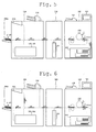
- a cross sectional structural arrangement of the various sections included in the image forming apparatus or the image forming system and an exemplary conveyance status of the paper sheet are schematically indicated.
- the image forming system includes an image forming apparatus 100, an intermediate apparatus 200 and a post processing apparatus 300.
- the image forming apparatus 100 forms an image on a paper sheet.
- the intermediate apparatus 200 serving as a subsequent stage of the image forming apparatus 100, reverses the paper sheet received therefrom.
- the post processing apparatus 300 applies various kinds of post processing to the paper sheet on which an image is already formed.
- the above-mentioned mode for coupling the concerned apparatuses to each other in the image forming system is merely an exemplified mode among various kinds of connection modes. Therefore, the scope of the present invention is not limited to the connection mode indicated by the drawings.
- the image forming apparatus 100 is constituted by a control section 101, a communication section 102, an operation display section 103, a storage section 104, a paper sheet feeding section 105, a conveyance section 110, an abnormality detecting section 115, a document reading section 120, an image data storage section 130, an image processing section 140 and an image forming section 150.
- the control section 101 controls not only operations to be performed by the various kinds of sections within the image forming apparatus 100, but also overall operations to be implemented in the system as a whole, serving as the post processing apparatus.
- the communication section 102 communicates with the other apparatuses currently coupled thereto.
- the operation display section 103 notifies the control section 101 of operation input signals generated corresponding to inputting operations performed by the user and displays current statuses of the image forming apparatus 100.
- the storage section 104 stores control programs and various kinds of setting data therein, and is used as a working area for executing the control programs.
- the paper sheet feeding section 105 feeds a paper sheet accommodated therein.
- the conveyance section 110 conveys the paper sheet, fed from the paper sheet feeding tray, or a paper sheet to be employed for an image forming operation, at a predetermined velocity.
- the document reading section 120 generates image data by scanning a document.
- the image data storage section 130 stores image data and various kinds of data, both to be used on an occasion of performing an image forming operation.
- the image processing section 140 implements various kinds of image processing necessary for the image forming operation. Based on image forming commands and processed image data acquired by applying the image processing to the image data, the image forming section 150 implements a printing operation (hereinafter, referred to as an "image forming operation").
- the abnormality detecting section 115 detects a primary abnormal state in which an operation for conveying a paper sheet cannot be continued due to the fact that the paper sheet has jammed at any one of the conveyance sections provided in the apparatus concerned, or a secondary abnormal state in which a certain negative influence would be possibly given to the image quality, such as an inclination of an image formed on the paper sheet, a dropout of an image to be formed on the paper sheet, or the like, due to an abnormality of the paper sheet conveyance operation, such as an inclined conveyance, a leaning conveyance to one side, a duplicate conveyance, etc.
- the paper jam occurrence status is defined as the primary abnormal state
- any one of the paper-sheet inclination occurrence status, the paper-sheet leaning occurrence status and the paper-sheet duplicate conveyance status, at the time of performing the conveyance operation is defined as the secondary abnormal state.
- the abnormality detecting section 115 notifies the control section 101 of the above-detected result.
- a sensor 115s1 shown in Fig. 2 , is employed for detecting the secondary abnormal state, such as a leaning or inclination of a paper sheet residing in the vicinity of the transferring point at which a toner image is transferred from an image bearing member to the paper sheet concerned, a duplicate conveyance operation erroneously performed by the paper sheet feeding section, a delay of timing for feeding a paper sheet residing at a pair of paper sheet feeding rollers or a resist roller, etc.
- the sensors (not shown in the drawings) are disposed at various places within the paper sheet conveyance sections.
- the paper sheet on which an image is already formed by the image forming apparatus 100 is conveyed out to the intermediate apparatus 200, serving as a subsequent stage of the image forming apparatus 100.
- the intermediate apparatus 200 is cascaded to the image forming apparatus 100 as the subsequent stage thereof
- the intermediate apparatus 200 is constituted by a control section 201, a communication section 202, a storage section 204, a conveyance path selecting section 205, a conveyance section 210, an abnormality detecting section 215 and a paper sheet reversing section 220.
- the control section 201 controls operations to be performed by the various kinds of sections disposed within the intermediate apparatus 200.
- the communication section 202 communicates with the image forming apparatus 100.
- the storage section 204 stores control programs and various kinds of setting data therein, and is used as a working area for executing the control programs.
- the conveyance path selecting section 205 selects a conveyance path to be currently employed for conveying the paper sheet.
- the conveyance section 210 conveys the paper sheet at a predetermined velocity.
- the abnormality detecting section 215 detects a paper jam by receiving signals outputted by sensors disposed at various kinds of positions within the conveyance sections of the intermediate apparatus 200.
- the paper sheet reversing section 220 conveys the paper sheet so as to reverse the paper sheet currently conveyed.
- the paper sheets conveyed through the intermediate apparatus 200 is conveyed out towards the paper sheet processing apparatus 300 serving as a subsequent stage thereof
- the post processing apparatus 300 is coupled to the image forming apparatus 100 as a subsequent stage of the image forming apparatus 100.
- the post processing apparatus 300 is constituted by a control section 301, a communication section 302, a storage section 304, an conveyance path selecting section 305, an ejection path selecting section 306, a conveyance section 310, an abnormality detecting section 315, a paper sheet inserting section 320, a punching section 330, a folding section 340, a binding section 350, a cutting section 360, a sub-tray ejecting section 390S and a main-tray ejecting section 390M.
- control section 301 controls various kinds of sections provided in the post processing apparatus 300.
- the communication section 302 communicates with the image forming apparatus 100.
- the storage section 304 stores control programs and various kinds of setting data therein, and is used as a working area for executing the control programs.
- the conveyance path selecting section 305 selects an insertion path through which the insertion paper sheet is to be inserted.
- the ejection path selecting section 306 selects an ejection path through which a bunch of post-processed paper sheets is to be ejected.
- the conveyance section 310 conveys the paper sheet at a predetermined velocity.
- the abnormality detecting section 315 detects a paper jam by receiving signals outputted by sensors disposed at various kinds of positions within the conveyance sections of the post processing apparatus 300.
- the paper sheet inserting section 320 inserts an insertion paper sheet, accommodated in a PI (Paper Inserter) section, into the paper sheet conveyance path.
- PI Paper Inserter
- the punching section 330 punches a binding hole onto the paper sheet.
- the folding section 340 folds the paper sheet in half or three.
- the binding section 350 applies a binding processing, such as a saddle-stitch processing, a side-staple processing, etc., to paper sheets so as to create a booklet.
- the cutting section 360 cuts the end portion of the booklet.
- the sub-tray ejecting section 390S ejects the paper sheet or the booklet onto the sub-tray shown in Fig. 2 , serving as an ejecting destination thereof
- the main-tray ejecting section 390M ejects the paper sheet or the booklet onto the main-tray shown in Fig.
- each of the paper sheet processing functions or each of the structural constituents, provided in the post processing apparatus 300 is indicated as merely an example.
- the scope of the present invention is not limited to the example indicated in the above.
- Fig. 3 shows a schematic diagram indicating an exemplified process that the paper sheets are conveyed within the image forming system.
- paper sheets p1 ⁇ p10 are fed from the paper sheet feeding section 105.
- paper sheets p1 ⁇ p3 are already ejected onto the main-tray ejecting section 390M, while paper sheets p4 ⁇ p10 remain at various positions within the image forming system.
- the pre-purge processing is defined as such a processing that makes it possible to continue the operation for conveying paper sheets currently remaining within the apparatus concerned though the operation for conveying the jam-causing paper sheet is disabled, instead of halting all operations for conveying the paper sheets currently residing within the apparatus as a whole.
- the control section 101 initializes settings established in each of the sections provided in the system (Step S101, shown in Fig. 4 ).
- the initializing operations above-mentioned are implemented according to the predetermined procedures so that each of various sections is made to be set at an initial position thereof, each of the voltage values and the detected values is established at a predetermined value.
- the control section 101 always monitors an issuance of a demand signal for commencing an image forming operation, which is to be issued from the operation display section 103 or an external computer (Step S102, shown in Fig. 4 ). Receiving the demand signal for commencing an image forming operation (Step S102; YES, shown in Fig. 4 ), the control section 101 controls the paper sheet feeding section 105, conveyance section 110, the image data storage section 130, the image processing section 140 and the image forming section 150, so as to form an image, based on image data designated, onto a paper sheet (Step S103, shown in Fig. 4 ).
- control section 101 controls the paper sheet reversing section 220 to perform the paper sheet reversing operation through the control section 201, as needed.
- control section 101 controls the punching section 330, the folding section 340, the binding section 350 and/or the cutting section 360 to perform designated paper-sheet processing through the control section 301, as needed.
- control section 101 controls the ejecting tray designated by the job in regard to the paper sheet to which the image forming operation and the paper sheet processing has been completed. For instance, the control section 101 controls the main-tray ejecting section 390M to eject the paper sheet onto a main-tray 390m through the control section 301 as indicated in the schematic diagram shown in Fig. 3 .
- any one of the abnormality detecting sections 115 through 315 detects the primary abnormal state or the secondary abnormal state, aforementioned, during the time when implementing the paper sheet conveyance operations associating with the image forming operation and the paper sheet processing (Step S104; YES, shown in Fig. 4 ).
- the control section 101 determines whether or not the concerned job has been completed in Step S105.
- the control section 101 finalizes the pre-purge processing (END), while, when determining that the job has not been completed (Step S105; NO, shown in Fig. 4 ), the control section 101 returns to Step S103.
- a paper sheet that causes the abnormality above-detected is defined as a "jam-causing paper sheet”.
- another paper sheet that currently remains at a position upstream from the jam-causing paper sheet is defined as a "jam-subsequent paper sheet”.
- Step S104 the control section 101 in conjunction with the control section 201 and/or the control section 301 controls the conveyance sections 110 through 310 so as to stop conveying the jam-causing paper sheet at the abnormality detected position (Step S106, shown in Fig. 4 ). Further, the control section 101 controls not only the paper sheet feeding section 105 to disable a next paper sheet feeding operation, but also the image forming section 150 to halt the image forming operation currently perfomned. In this connection, the control section 101 controls the conveyance sections 110 through 310 so as to continue the operation for conveying the paper sheet, the feeding operation of which has been already commenced.
- the schematic diagram shown in Fig. 5 shows such a case that an abnormality of the paper sheet p4 has been detected at a position just before the main tray 390m in midcourse of the conveying operation thereof, and the paper sheet p4 is determined as the jam-causing paper sheet, the conveying operation of which is halted.
- the paper sheets p5 through p10 correspond to the jam-subsequent paper sheets.
- the control section 101 conducts controlling operations so as to continue the conveying operation thereof
- the control section 101 conducts controlling operations so as to halt the image forming operation currently performed and to disable the operation for newly feeding a next paper sheet.
- the control section 101 determines a specific ejecting tray (separate ejecting tray), other than the ejecting tray (designated ejecting tray) designated in regard to the job concerned, as an ejecting destination tray onto which the jam-subsequent paper sheets are to be ejected (Step S107, shown in Fig. 4 ).
- the ejecting tray (designated ejecting tray) designated in regard to the job concerned is the main tray 390m as shown in Fig. 5 .
- the sub-tray 390s corresponds to the specific ejecting tray (separate ejecting tray) other than the designated ejecting tray.
- control section 101 in conjunction with the control section 201 and/or the control section 301 determines whether it is possible or impossible to eject the jam-subsequent paper sheets onto the separate ejecting tray (Step S108, shown in Fig. 4 ).
- Step S108 it is possible to determine whether it is possible or impossible to eject the jam-subsequent paper sheets onto the separate ejecting tray, from the relationship between the conveyance path branching position at which the designated ejecting tray and the separate ejecting tray are branched from each other, and the current position of the jam-subsequent paper sheet at the time when the abnormality has been detected.
- Step S108 when determining that it is impossible to eject the jam-subsequent paper sheet onto the separate ejecting tray (Step S108; NO, shown in Fig. 4 ), the control section 101 in conjunction with the control section 201 and/or the control section 301 controls the conveyance sections 110 through 310 so as to halt the operation for conveying the jam-subsequent paper sheet at the existing position thereof (Step S109, shown in Fig. 4 ).
- Step S109 shown in a case where the jam-subsequent paper sheet resides near the jam-causing paper sheet and downstream from the branching point towards the separate ejecting tray, impossibility of ejecting the jam-causing paper sheet onto the separate ejecting tray may occur.
- Step S108 it is desirable that the determining operation in Step S108 is performed in order of the jam-subsequent paper sheet that resides near the jam-causing paper sheet, first. Further, after the pre-purge processing has been completed, the user may remove both the jam-causing paper sheet and the jam-subsequent paper sheet that could not be ejected onto the separate ejecting tray from the image forming system concerned.
- Step S108 when determining that it is possible to eject the jam-subsequent paper sheet onto the separate ejecting tray (Step S108; YES, shown in Fig. 4 ), the control section 101 in conjunction with the control section 201 and/or the control section 301 controls the conveyance sections 110 through 310 so as to continue the operation for conveying the jam-subsequent paper sheet and to eject it onto the separate ejecting tray, without halting the conveyance operation thereof
- the abnormality detecting sections 115 through 315 perform operations for detecting the primary abnormal state or the secondary abnormal state (Step S 110 and Step S 112, shown in Fig. 4 ).
- the operation for detecting the primary abnormal state is performed (Step S110, shown in Fig. 4 ), and as a result, when the primary abnormal state is not detected (Step S110; NO, shown in Fig. 4 ), the operation for detecting the secondary abnormal state is to be performed (Step S 112, shown in Fig. 4 ).
- the abnormality detecting section 115 notifies the control section 101 of the result detected thereby. Further, the abnormality detecting section 215 notifies the control section 101 of the result detected thereby, through the control section 201. Still further, the abnormality detecting section 315 notifies the control section 101 of the result detected thereby, through the control section 301. Then, all of the abnormality detected results are consolidated into the control section 101.
- Step S110 since the jam-subsequent paper sheet, detected as in the primary abnormal state (Step S110; YES, shown in Fig. 4 ), currently enters into such a state that the conveyance operation cannot be continued due to occurrence of the paper jam in midcourse of conveying the jam-subsequent paper sheet concerned, the control section 101 newly recognizes the concerned paper sheet as the jam-causing paper sheet, and controls the conveyance sections 110 through 310 so as to halt the conveyance operation thereof at the jam detected position (Step S111, shown in Fig. 4 ).
- Step S108 the control section 101 returns to Step S108 so as to commence the processing of the next paper sheet newly established as the jam-subsequent paper sheet.
- Step S110 when determining that the primary abnormal state is not detected in the jam-subsequent paper sheet (Step S110; NO, shown in Fig. 4 ) and when determining that the secondary abnormal state is detected in the jam-subsequent paper sheet (Step S112; YES, shown in Fig. 4 ), various kinds of image failures, such as a leaning of image to one side, an inclination of image, a dropout of image, etc., may be possibly generated in the image formed on the jam-subsequent paper sheet, though it is possible to convey the paper sheet concerned.
- the control section 101 confirms whether or not the jam-subsequent paper sheet corresponding to the secondary abnormal state is scheduled to be utilized (Step S 113, shown in Fig. 4 ).
- the determination in regard to whether or not the jam-subsequent paper sheet corresponding to the secondary abnormal state is scheduled to be utilized as an image forming output product is established in advance by inputting operations performed on the operation display section 103 or by the external computer, etc. Further, in a case where the determination is not established as "SCHEDULED TO BE UTILIZED", the determination may be regarded as "NOT SCHEDULED TO BE UTILIZED".
- Step S 112 when determining that the jam-subsequent paper sheet corresponds to the secondary abnormal state (Step S 112; YES, shown in Fig. 4 ) and when determining that the jam-subsequent paper sheet concerned is scheduled to be utilized without being wasted (Step S113; YES, shown in Fig. 4 ), the image quality thereof may be possibly suffered from a certain adverse influence since the jam-subsequent paper sheet corresponds to the secondary abnormal state. In other words, it is undesirable to utilize such the jam-subsequent paper sheet in a normal way.
- the control section newly establishes the paper sheet, corresponding to the secondary abnormal state and scheduled to be utilize, as the jam-causing paper sheet, and then, controls the conveyance sections 110 through 310 so as to halt the conveyance operation thereof at the abnormality detected position (Step S111, shown in Fig. 4 ). Then, with respect to the next paper sheet followed by the preceding paper sheet, which has been newly recognized as the jam-causing paper sheet as a result of detecting the secondary abnormal state in the above, the control section 101 returns to Step S108 so as to commence the processing of the next paper sheet newly established as the jam-subsequent paper sheet.
- Step S 110 when determining that neither the primary abnormal state nor the secondary abnormal state is detected in respect to the jam-subsequent paper sheet (Step S 110; NO, Step S 112; NO, shown in Fig. 4 ), or when determining that the primary abnormal state is not detected but the secondary abnormal state is detected in respect to the jam-subsequent paper sheet and the jam-subsequent paper sheet concerned is not scheduled to be utilized (Step S110; NO, Step S112; YES, Step S113; NO, shown in Fig. 4 ), the control section 101 continues to conduct the operations for conveying and ejecting the jam-subsequent paper sheet concerned as the pre-purge processing (Step S 114, shown in Fig. 4 ).
- control section 101 implements the operations for detecting the primary abnormal state or the secondary abnormal state and the operations for controlling the conveyance operation (Step S108 through Step S 114, shown in Fig. 4 ) for every one of the jam-subsequent paper sheets (Step S 115, shown in Fig. 4 ).
- the control section 101 in conjunction with the control section 201 and the control section 301 halts the operations for conveying the jam-causing paper sheet, the jam-subsequent paper sheet that is newly recognized as the jam-causing paper sheet in midcourse of the conveyance operation of the pre-purge processing, and the other jam-subsequent paper sheet that cannot be ejected onto the separate ejecting tray. Then, the control section 101 in conjunction with the control section 201 and the control section 301 continues the operation for conveying still the other jam-subsequent paper sheet that can be ejected onto the separate ejecting tray, so as to eject it thereon. At this time, the control section 101 controls each of the sections so as to halt the operations for implementing the pre-purge processing (Step S116, shown in Fig. 4 ).
- the schematic diagram shown in Fig. 5 shows such a case that, after the paper sheets p1 through p3 have been ejected onto the main tray 390m, the primary abnormal state of the paper sheet p4 has been detected at a position just before the main tray 390m in midcourse of the conveying operation thereof, and the paper sheet p4 is determined as the jam-causing paper sheet, the conveying operation of which is halted.
- the paper sheets p5 through p10 correspond to the jam-subsequent paper sheets, the aforementioned pre-purge processing is applied to the paper sheets p5 through p10. In addition, the operation for feeding the next paper sheet is disabled.
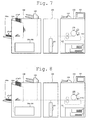
- the paper sheet p5 serving as the jam-subsequent paper sheet is conveyed towards the sub-tray 390s, as shown in Fig. 6 .
- the paper sheets p5 through p10 which currently remain at the positions within the image forming system as the jam-subsequent paper sheets, are conveyed towards the sub-tray 390s and ejected thereon.
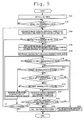
- Fig. 9 is a flowchart indicating a flow of operating steps as a modified example of the controlling operations in the pre-purge processing aforementioned.
- the step same as that in the flowchart shown in Fig. 4 is attached with the same number, and duplicated explanations therefore will be omitted.
- Step S 112' the control section 101 determines not only whether or not the primary abnormal state is detected (Step S110, shown in Fig. 9 ), but also whether or not the secondary abnormal state is detected (Step S 113', shown in Fig. 9 ). In this case, actually, the processing same as those in the flowchart shown in Fig. 4 are performed, though the processing order in the flowchart shown in Fig. 9 is different from that in the flowchart shown in Fig. 4 .
- Step S 112' With respect to the jam-subsequent paper sheet that is not scheduled to be utilized (Step S 112'; NO, shown in Fig. 9 ), although the control section 101 determines whether or not the primary abnormal state is detected (Step S110, shown in Fig. 9 ), the control section 101 skips Step S 113' for determining whether or not the secondary abnormal state is detected, and continues the operations for conveying and ejecting the jam-subsequent paper sheet as the pre-purge processing (Step S 114, shown in Fig. 9 ). According to the above-mentioned, compared to the processing indicated in the flowchart shown in Fig. 4 , since the operation for detecting the secondary abnormal state is skipped, it becomes possible to reduce the processing burden to be incurred to the control section 101, and accordingly, it becomes possible to implement the pre-purge processing effectively.
- Fig. 10 is a schematic diagram showing an example of a display screen 103a1 to be displayed by the operation display section 103.
- the jam-subsequent paper sheet which has been determined as in the secondary abnormal state possibly causing a certain adverse influence onto an image formed thereon, is not scheduled to be utilized as an image forming output product, or, in a case where it is not established whether or not the concerned jam-subsequent paper sheet is scheduled to be utilized and the jam-subsequent paper sheet determined as in the secondary abnormal state is to be ejected (Step S 112; Yes, Step S113; NO, Step S 114, shown in Fig.
- Step S112' NO, Step S114, shown in Fig. 9
- the control section 101 controls the operation display section 103 so as to display the display screen 103a1 thereon.
- a pop-up display screen 103a11 is displayed in order to indicate the fact that the pre-purge processing for ejecting a jam-subsequent paper sheet onto the sub-tray is currently implemented, irrespective of occurrence of leaning, inclination and/or duplicate conveyance of the paper sheets in the secondary abnormal state.
- the message indicating "[ATTENTION PLEASE] NOW, PRE-PURGE PROCESSING FOR EJECTING JAM-SUBSEQUENT PAPER SHEET ONTO SUB-TRAY IS GOING ON, IRRESPECTIVE OF LEANING, INCLINATION AND/OR DUPLICATE CONVEYANCE THEREOF"
- the message indicating "[ATTENTION PLEASE] NOW, PRE-PURGE PROCESSING FOR EJECTING JAM-SUBSEQUENT PAPER SHEET ONTO SUB-TRAY IS GOING ON, IRRESPECTIVE OF LEANING, INCLINATION AND/OR DUPLICATE CONVEYANCE THEREOF”
- the message indicating "[ATTENTION PLEASE] NOW, PRE-PURGE PROCESSING FOR EJECTING JAM-SUBSEQUENT PAPER SHEET ONTO SUB-TRAY IS GOING ON, IRRESPECTIVE OF LEANING, INCLINATION AND/OR DUPLICATE CONVEYANCE THEREOF"
- the primary abnormal state in which the conveyance section is incapable of continuing the operation for conveying said paper sheet and the secondary abnormal state in which an adverse influence is possibly incurred to the image formed on the paper sheet though the conveyance section is capable of continuing the operation for conveying the paper sheet, are defined.
- the control section 101 conducts controlling operations so as to continue the operation for conveying the paper sheet without halting the operation for conveying the paper sheet, even if the secondary abnormal state in respect to the jam-subsequent paper sheet is detected in midcourse of performing the pre-purge processing thereof
- the control section conducts controlling operations so as to halt the operation for conveying the paper sheet without continuing the operation for conveying the paper sheet.
- the control section conducts controlling operations so as to halt the operation for conveying the paper sheet without continuing the operation for conveying the paper sheet.
- control section has a function for accepting a setting established by determining whether or not the jam-subsequent paper sheet ejected in the pre-purge processing is to be utilized.
- the control section 101 controls the display section 103 to display a message indicating that the operation for conveying the paper sheet is continued in the secondary abnormal state currently detected, thereon.
- the ejecting section is provided with a plurality of ejecting trays being independent from each other.
- the control section conducts the controlling operations so that the paper sheet, in which neither the primary abnormal state nor the secondary abnormal state is detected, is ejected onto one of the plurality of ejecting trays, while the jam-subsequent paper sheet, which is to be conveyed in the pre-purge processing, is ejected onto another one of the plurality of ejecting trays.
- control section 101 provided in the image forming apparatus 100 serves as the central section performing the controlling operations at the time when the pre-purge processing is implemented, has been exemplified as an embodiment of the present invention.
- the scope of the present invention is not limited to the above-mentioned embodiment.
- any one of the control section 201 and the control section 301 respectively provided in the intermediate apparatus 200 and the post processing apparatus 300, other than the image forming apparatus 100 may instruct the other control sections to implement the pre-purge processing same as the above-mentioned.
- the system is so constituted that each of the control sections 101 through 301 independently implements the pre-purge processing, and then, notifies the other control sections of the results of the controlling operations implemented in its own apparatus.
- the operation display section not only in the image forming apparatus 100, but also in any one of the intermediate apparatus 200 and the post processing apparatus 300. Further, it is also possible to employ an operating section and/or a display section, which is provided in an external computer coupled to the image forming system through a network.
- the secondary abnormal state is defined as such a state that a certain adverse influence is incurred to the image quality of the image formed on the paper sheet in midcourse of the conveying operation thereof, such as an inclination of the image, a dropout of the image, etc.
- the secondary abnormal state is not limited to the leaning to one side, the inclination and the duplicate conveyance thereof, and may include other adverse states.
Landscapes
- Physics & Mathematics (AREA)
- General Physics & Mathematics (AREA)
- Engineering & Computer Science (AREA)
- Mechanical Engineering (AREA)
- Control Or Security For Electrophotography (AREA)
- Paper Feeding For Electrophotography (AREA)
- Facsimiles In General (AREA)
- Accessory Devices And Overall Control Thereof (AREA)
- Fixing For Electrophotography (AREA)
- Controlling Sheets Or Webs (AREA)
Applications Claiming Priority (1)
| Application Number | Priority Date | Filing Date | Title |
|---|---|---|---|
| JP2013259462A JP5900477B2 (ja) | 2013-12-16 | 2013-12-16 | 画像形成装置及び画像形成システム並びに画像形成制御方法 |
Publications (3)
| Publication Number | Publication Date |
|---|---|
| EP2884342A2 true EP2884342A2 (de) | 2015-06-17 |
| EP2884342A3 EP2884342A3 (de) | 2015-08-26 |
| EP2884342B1 EP2884342B1 (de) | 2020-09-23 |
Family
ID=52272840
Family Applications (1)
| Application Number | Title | Priority Date | Filing Date |
|---|---|---|---|
| EP14198149.8A Active EP2884342B1 (de) | 2013-12-16 | 2014-12-16 | Bilderzeugungsvorrichtung, Bilderzeugungssystem und Verfahren zur Steuerung davon |
Country Status (4)
| Country | Link |
|---|---|
| US (1) | US9857752B2 (de) |
| EP (1) | EP2884342B1 (de) |
| JP (1) | JP5900477B2 (de) |
| CN (1) | CN104717391B (de) |
Cited By (1)
| Publication number | Priority date | Publication date | Assignee | Title |
|---|---|---|---|---|
| EP3409481A1 (de) * | 2017-05-30 | 2018-12-05 | OCE Holding B.V. | Drucksystem |
Families Citing this family (11)
| Publication number | Priority date | Publication date | Assignee | Title |
|---|---|---|---|---|
| JP6233359B2 (ja) * | 2015-07-10 | 2017-11-22 | コニカミノルタ株式会社 | 画像形成装置 |
| US9760051B2 (en) * | 2016-01-26 | 2017-09-12 | Kabushiki Kaisha Toshiba | Post-processing apparatus and image forming system |
| JP6898580B2 (ja) * | 2016-07-20 | 2021-07-07 | コニカミノルタ株式会社 | 画像形成システムおよび制御方法 |
| JP6803198B2 (ja) * | 2016-10-31 | 2020-12-23 | 理想科学工業株式会社 | 印刷装置 |
| JP6961956B2 (ja) * | 2017-03-06 | 2021-11-05 | コニカミノルタ株式会社 | 画像形成装置、画像形成方法、および画像形成プログラム |
| CN110083027B (zh) * | 2018-01-26 | 2022-04-05 | 柯尼卡美能达办公系统研发(无锡)有限公司 | 原稿搬送装置 |
| JP7234524B2 (ja) * | 2018-07-24 | 2023-03-08 | コニカミノルタ株式会社 | 画像形成システム及びプログラム |
| JP7280552B2 (ja) * | 2019-03-18 | 2023-05-24 | コニカミノルタ株式会社 | 画像形成システムおよび異常紙情報表示方法 |
| JP7415379B2 (ja) * | 2019-09-03 | 2024-01-17 | 富士フイルムビジネスイノベーション株式会社 | 記録材搬送装置および画像形成装置 |
| JP7528553B2 (ja) * | 2020-06-12 | 2024-08-06 | 株式会社リコー | ラミネート処理装置、画像形成装置及び画像形成システム |
| JP2024088182A (ja) * | 2022-12-20 | 2024-07-02 | 京セラドキュメントソリューションズ株式会社 | 用紙搬送装置 |
Citations (5)
| Publication number | Priority date | Publication date | Assignee | Title |
|---|---|---|---|---|
| JPH07120984A (ja) | 1993-10-21 | 1995-05-12 | Fuji Xerox Co Ltd | 画像形成装置の用紙搬送装置 |
| JPH11292389A (ja) | 1998-04-10 | 1999-10-26 | Fuji Xerox Co Ltd | 印刷装置及び印刷システム |
| JP2003280304A (ja) | 2002-03-20 | 2003-10-02 | Ricoh Co Ltd | 画像形成装置 |
| JP2006343727A (ja) | 2005-05-13 | 2006-12-21 | Canon Inc | 画像形成システム及び画像形成方法 |
| JP2008052125A (ja) | 2006-08-25 | 2008-03-06 | Ricoh Co Ltd | 両面画像形成装置および両面画像形成方法 |
Family Cites Families (15)
| Publication number | Priority date | Publication date | Assignee | Title |
|---|---|---|---|---|
| JPH08118752A (ja) * | 1994-10-19 | 1996-05-14 | Fuji Xerox Co Ltd | イメージング処理方法 |
| JP2679695B2 (ja) * | 1995-11-13 | 1997-11-19 | 富士ゼロックス株式会社 | 複写機の用紙搬送制御装置 |
| US6078760A (en) * | 1997-07-14 | 2000-06-20 | Seiko Epson Corporation | Image forming apparatus having an inverse and re-fixing sub-mode |
| JP4035355B2 (ja) * | 2002-04-08 | 2008-01-23 | キヤノン株式会社 | 異常シート識別機能付き画像形成装置 |
| US7228079B2 (en) * | 2004-08-03 | 2007-06-05 | Hewlett-Packard Development Company, L.P. | Method and apparatus for detecting a media jam |
| JP4510652B2 (ja) * | 2005-01-28 | 2010-07-28 | キヤノン株式会社 | 画像処理装置、情報処理方法、ならびにプログラム、記憶媒体 |
| US7636543B2 (en) * | 2005-11-30 | 2009-12-22 | Xerox Corporation | Radial merge module for printing system |
| US20080175607A1 (en) * | 2007-01-18 | 2008-07-24 | Xerox Corporation | System prompt of dual top tray/purge tray prior to output/purged sheets being sent to the top tray |
| JP4909206B2 (ja) * | 2007-08-08 | 2012-04-04 | 株式会社リコー | 画像形成装置 |
| US20090110411A1 (en) * | 2007-10-31 | 2009-04-30 | Xerox Corporation | Printing system and method for purging print media |
| JP2010026477A (ja) * | 2008-06-16 | 2010-02-04 | Ricoh Co Ltd | 画像形成装置 |
| JP2010140009A (ja) | 2008-11-12 | 2010-06-24 | Canon Inc | 画像形成装置 |
| JP2010120297A (ja) * | 2008-11-20 | 2010-06-03 | Riso Kagaku Corp | 両面印刷装置 |
| JP2011046492A (ja) * | 2009-08-27 | 2011-03-10 | Canon Inc | シート搬送装置及び画像形成装置 |
| JP5842675B2 (ja) * | 2012-03-06 | 2016-01-13 | コニカミノルタ株式会社 | 画像形成装置 |
-
2013
- 2013-12-16 JP JP2013259462A patent/JP5900477B2/ja not_active Expired - Fee Related
-
2014
- 2014-12-16 CN CN201410781505.6A patent/CN104717391B/zh active Active
- 2014-12-16 US US14/572,483 patent/US9857752B2/en active Active
- 2014-12-16 EP EP14198149.8A patent/EP2884342B1/de active Active
Patent Citations (5)
| Publication number | Priority date | Publication date | Assignee | Title |
|---|---|---|---|---|
| JPH07120984A (ja) | 1993-10-21 | 1995-05-12 | Fuji Xerox Co Ltd | 画像形成装置の用紙搬送装置 |
| JPH11292389A (ja) | 1998-04-10 | 1999-10-26 | Fuji Xerox Co Ltd | 印刷装置及び印刷システム |
| JP2003280304A (ja) | 2002-03-20 | 2003-10-02 | Ricoh Co Ltd | 画像形成装置 |
| JP2006343727A (ja) | 2005-05-13 | 2006-12-21 | Canon Inc | 画像形成システム及び画像形成方法 |
| JP2008052125A (ja) | 2006-08-25 | 2008-03-06 | Ricoh Co Ltd | 両面画像形成装置および両面画像形成方法 |
Cited By (1)
| Publication number | Priority date | Publication date | Assignee | Title |
|---|---|---|---|---|
| EP3409481A1 (de) * | 2017-05-30 | 2018-12-05 | OCE Holding B.V. | Drucksystem |
Also Published As
| Publication number | Publication date |
|---|---|
| JP5900477B2 (ja) | 2016-04-06 |
| EP2884342B1 (de) | 2020-09-23 |
| JP2015118116A (ja) | 2015-06-25 |
| CN104717391B (zh) | 2018-04-17 |
| EP2884342A3 (de) | 2015-08-26 |
| US9857752B2 (en) | 2018-01-02 |
| CN104717391A (zh) | 2015-06-17 |
| US20150168907A1 (en) | 2015-06-18 |
Similar Documents
| Publication | Publication Date | Title |
|---|---|---|
| EP2884342B1 (de) | Bilderzeugungsvorrichtung, Bilderzeugungssystem und Verfahren zur Steuerung davon | |
| JP5627222B2 (ja) | 印刷装置、印刷装置の制御方法、及びプログラム | |
| US20140241737A1 (en) | Sheet processing apparatus, image forming system, and sheet processing control method | |
| US20170023901A1 (en) | Sheet conveyance apparatus, image forming apparatus, and image forming system | |
| JP5954277B2 (ja) | 画像形成システムおよびプログラム | |
| JP5928207B2 (ja) | 画像形成システム | |
| JP4948369B2 (ja) | 情報処理装置及び印刷制御方法 | |
| US8908215B2 (en) | Image forming system, paper sheet processing apparatus and method for controlling paper sheet processing | |
| EP1352760B1 (de) | Abgabeverarbeitungsgerät und Bilderzeugungsgerät | |
| EP1352866B1 (de) | Abgabeverarbeitungsgerät und Bilderzeugungsgerät | |
| US9678466B2 (en) | Image forming apparatus that controls a conveyance speed of sheets while purging the sheets after a paper jam | |
| US10479638B2 (en) | Printing system | |
| US20140339756A1 (en) | Printing apparatus and control method thereof | |
| US20130235411A1 (en) | Printing apparatus, printing apparatus control method, and storage medium storing a program | |
| US8982402B2 (en) | Image forming system and image forming system communication control method | |
| US9772595B2 (en) | Image forming system, image forming device, post-processing device, and non-transitory computer readable recording medium stored with conveyance abnormity detection program | |
| US20140334833A1 (en) | Sheet conveying apparatus, method for controlling the same and program | |
| US9183470B2 (en) | Image forming apparatus, system, and method for handling retention sheets | |
| JP6314422B2 (ja) | 画像形成システム | |
| JP2007106559A (ja) | 画像形成装置、シート処理装置および画像形成システム | |
| US20160191720A1 (en) | Image forming system, image forming apparatus, and image formation control program | |
| US20140167345A1 (en) | Printing system, control method, and storage medium storing program | |
| JP4510767B2 (ja) | 用紙処理システム | |
| JP6186857B2 (ja) | 画像形成システム | |
| JPH0542353B2 (de) |
Legal Events
| Date | Code | Title | Description |
|---|---|---|---|
| PUAI | Public reference made under article 153(3) epc to a published international application that has entered the european phase |
Free format text: ORIGINAL CODE: 0009012 |
|
| 17P | Request for examination filed |
Effective date: 20141216 |
|
| AK | Designated contracting states |
Kind code of ref document: A2 Designated state(s): AL AT BE BG CH CY CZ DE DK EE ES FI FR GB GR HR HU IE IS IT LI LT LU LV MC MK MT NL NO PL PT RO RS SE SI SK SM TR |
|
| AX | Request for extension of the european patent |
Extension state: BA ME |
|
| PUAL | Search report despatched |
Free format text: ORIGINAL CODE: 0009013 |
|
| AK | Designated contracting states |
Kind code of ref document: A3 Designated state(s): AL AT BE BG CH CY CZ DE DK EE ES FI FR GB GR HR HU IE IS IT LI LT LU LV MC MK MT NL NO PL PT RO RS SE SI SK SM TR |
|
| AX | Request for extension of the european patent |
Extension state: BA ME |
|
| RIC1 | Information provided on ipc code assigned before grant |
Ipc: B65H 29/00 20060101ALI20150721BHEP Ipc: G03G 15/00 20060101AFI20150721BHEP |
|
| R17P | Request for examination filed (corrected) |
Effective date: 20160225 |
|
| RBV | Designated contracting states (corrected) |
Designated state(s): AL AT BE BG CH CY CZ DE DK EE ES FI FR GB GR HR HU IE IS IT LI LT LU LV MC MK MT NL NO PL PT RO RS SE SI SK SM TR |
|
| RIN1 | Information on inventor provided before grant (corrected) |
Inventor name: KONISHI, HIROYUKI Inventor name: NISHI, YOUICHIROU |
|
| GRAP | Despatch of communication of intention to grant a patent |
Free format text: ORIGINAL CODE: EPIDOSNIGR1 |
|
| STAA | Information on the status of an ep patent application or granted ep patent |
Free format text: STATUS: GRANT OF PATENT IS INTENDED |
|
| INTG | Intention to grant announced |
Effective date: 20200515 |
|
| RIC1 | Information provided on ipc code assigned before grant |
Ipc: B65H 29/00 20060101ALI20200504BHEP Ipc: B65H 31/24 20060101ALI20200504BHEP Ipc: G03G 15/00 20060101AFI20200504BHEP Ipc: B65H 29/60 20060101ALI20200504BHEP Ipc: B65H 43/00 20060101ALI20200504BHEP |
|
| GRAS | Grant fee paid |
Free format text: ORIGINAL CODE: EPIDOSNIGR3 |
|
| GRAA | (expected) grant |
Free format text: ORIGINAL CODE: 0009210 |
|
| STAA | Information on the status of an ep patent application or granted ep patent |
Free format text: STATUS: THE PATENT HAS BEEN GRANTED |
|
| AK | Designated contracting states |
Kind code of ref document: B1 Designated state(s): AL AT BE BG CH CY CZ DE DK EE ES FI FR GB GR HR HU IE IS IT LI LT LU LV MC MK MT NL NO PL PT RO RS SE SI SK SM TR |
|
| REG | Reference to a national code |
Ref country code: GB Ref legal event code: FG4D |
|
| REG | Reference to a national code |
Ref country code: CH Ref legal event code: EP |
|
| REG | Reference to a national code |
Ref country code: DE Ref legal event code: R096 Ref document number: 602014070433 Country of ref document: DE |
|
| REG | Reference to a national code |
Ref country code: IE Ref legal event code: FG4D |
|
| REG | Reference to a national code |
Ref country code: AT Ref legal event code: REF Ref document number: 1317003 Country of ref document: AT Kind code of ref document: T Effective date: 20201015 |
|
| PG25 | Lapsed in a contracting state [announced via postgrant information from national office to epo] |
Ref country code: BG Free format text: LAPSE BECAUSE OF FAILURE TO SUBMIT A TRANSLATION OF THE DESCRIPTION OR TO PAY THE FEE WITHIN THE PRESCRIBED TIME-LIMIT Effective date: 20201223 Ref country code: GR Free format text: LAPSE BECAUSE OF FAILURE TO SUBMIT A TRANSLATION OF THE DESCRIPTION OR TO PAY THE FEE WITHIN THE PRESCRIBED TIME-LIMIT Effective date: 20201224 Ref country code: NO Free format text: LAPSE BECAUSE OF FAILURE TO SUBMIT A TRANSLATION OF THE DESCRIPTION OR TO PAY THE FEE WITHIN THE PRESCRIBED TIME-LIMIT Effective date: 20201223 Ref country code: SE Free format text: LAPSE BECAUSE OF FAILURE TO SUBMIT A TRANSLATION OF THE DESCRIPTION OR TO PAY THE FEE WITHIN THE PRESCRIBED TIME-LIMIT Effective date: 20200923 Ref country code: HR Free format text: LAPSE BECAUSE OF FAILURE TO SUBMIT A TRANSLATION OF THE DESCRIPTION OR TO PAY THE FEE WITHIN THE PRESCRIBED TIME-LIMIT Effective date: 20200923 Ref country code: FI Free format text: LAPSE BECAUSE OF FAILURE TO SUBMIT A TRANSLATION OF THE DESCRIPTION OR TO PAY THE FEE WITHIN THE PRESCRIBED TIME-LIMIT Effective date: 20200923 |
|
| REG | Reference to a national code |
Ref country code: AT Ref legal event code: MK05 Ref document number: 1317003 Country of ref document: AT Kind code of ref document: T Effective date: 20200923 |
|
| PG25 | Lapsed in a contracting state [announced via postgrant information from national office to epo] |
Ref country code: RS Free format text: LAPSE BECAUSE OF FAILURE TO SUBMIT A TRANSLATION OF THE DESCRIPTION OR TO PAY THE FEE WITHIN THE PRESCRIBED TIME-LIMIT Effective date: 20200923 Ref country code: LV Free format text: LAPSE BECAUSE OF FAILURE TO SUBMIT A TRANSLATION OF THE DESCRIPTION OR TO PAY THE FEE WITHIN THE PRESCRIBED TIME-LIMIT Effective date: 20200923 |
|
| REG | Reference to a national code |
Ref country code: NL Ref legal event code: MP Effective date: 20200923 |
|
| REG | Reference to a national code |
Ref country code: LT Ref legal event code: MG4D |
|
| PG25 | Lapsed in a contracting state [announced via postgrant information from national office to epo] |
Ref country code: PT Free format text: LAPSE BECAUSE OF FAILURE TO SUBMIT A TRANSLATION OF THE DESCRIPTION OR TO PAY THE FEE WITHIN THE PRESCRIBED TIME-LIMIT Effective date: 20210125 Ref country code: LT Free format text: LAPSE BECAUSE OF FAILURE TO SUBMIT A TRANSLATION OF THE DESCRIPTION OR TO PAY THE FEE WITHIN THE PRESCRIBED TIME-LIMIT Effective date: 20200923 Ref country code: NL Free format text: LAPSE BECAUSE OF FAILURE TO SUBMIT A TRANSLATION OF THE DESCRIPTION OR TO PAY THE FEE WITHIN THE PRESCRIBED TIME-LIMIT Effective date: 20200923 Ref country code: RO Free format text: LAPSE BECAUSE OF FAILURE TO SUBMIT A TRANSLATION OF THE DESCRIPTION OR TO PAY THE FEE WITHIN THE PRESCRIBED TIME-LIMIT Effective date: 20200923 Ref country code: SM Free format text: LAPSE BECAUSE OF FAILURE TO SUBMIT A TRANSLATION OF THE DESCRIPTION OR TO PAY THE FEE WITHIN THE PRESCRIBED TIME-LIMIT Effective date: 20200923 Ref country code: EE Free format text: LAPSE BECAUSE OF FAILURE TO SUBMIT A TRANSLATION OF THE DESCRIPTION OR TO PAY THE FEE WITHIN THE PRESCRIBED TIME-LIMIT Effective date: 20200923 Ref country code: CZ Free format text: LAPSE BECAUSE OF FAILURE TO SUBMIT A TRANSLATION OF THE DESCRIPTION OR TO PAY THE FEE WITHIN THE PRESCRIBED TIME-LIMIT Effective date: 20200923 |
|
| PG25 | Lapsed in a contracting state [announced via postgrant information from national office to epo] |
Ref country code: PL Free format text: LAPSE BECAUSE OF FAILURE TO SUBMIT A TRANSLATION OF THE DESCRIPTION OR TO PAY THE FEE WITHIN THE PRESCRIBED TIME-LIMIT Effective date: 20200923 Ref country code: IS Free format text: LAPSE BECAUSE OF FAILURE TO SUBMIT A TRANSLATION OF THE DESCRIPTION OR TO PAY THE FEE WITHIN THE PRESCRIBED TIME-LIMIT Effective date: 20210123 Ref country code: ES Free format text: LAPSE BECAUSE OF FAILURE TO SUBMIT A TRANSLATION OF THE DESCRIPTION OR TO PAY THE FEE WITHIN THE PRESCRIBED TIME-LIMIT Effective date: 20200923 Ref country code: AT Free format text: LAPSE BECAUSE OF FAILURE TO SUBMIT A TRANSLATION OF THE DESCRIPTION OR TO PAY THE FEE WITHIN THE PRESCRIBED TIME-LIMIT Effective date: 20200923 Ref country code: AL Free format text: LAPSE BECAUSE OF FAILURE TO SUBMIT A TRANSLATION OF THE DESCRIPTION OR TO PAY THE FEE WITHIN THE PRESCRIBED TIME-LIMIT Effective date: 20200923 |
|
| REG | Reference to a national code |
Ref country code: DE Ref legal event code: R097 Ref document number: 602014070433 Country of ref document: DE |
|
| PG25 | Lapsed in a contracting state [announced via postgrant information from national office to epo] |
Ref country code: SK Free format text: LAPSE BECAUSE OF FAILURE TO SUBMIT A TRANSLATION OF THE DESCRIPTION OR TO PAY THE FEE WITHIN THE PRESCRIBED TIME-LIMIT Effective date: 20200923 |
|
| PLBE | No opposition filed within time limit |
Free format text: ORIGINAL CODE: 0009261 |
|
| REG | Reference to a national code |
Ref country code: CH Ref legal event code: PL |
|
| STAA | Information on the status of an ep patent application or granted ep patent |
Free format text: STATUS: NO OPPOSITION FILED WITHIN TIME LIMIT |
|
| PG25 | Lapsed in a contracting state [announced via postgrant information from national office to epo] |
Ref country code: DK Free format text: LAPSE BECAUSE OF FAILURE TO SUBMIT A TRANSLATION OF THE DESCRIPTION OR TO PAY THE FEE WITHIN THE PRESCRIBED TIME-LIMIT Effective date: 20200923 Ref country code: MC Free format text: LAPSE BECAUSE OF FAILURE TO SUBMIT A TRANSLATION OF THE DESCRIPTION OR TO PAY THE FEE WITHIN THE PRESCRIBED TIME-LIMIT Effective date: 20200923 Ref country code: SI Free format text: LAPSE BECAUSE OF FAILURE TO SUBMIT A TRANSLATION OF THE DESCRIPTION OR TO PAY THE FEE WITHIN THE PRESCRIBED TIME-LIMIT Effective date: 20200923 |
|
| 26N | No opposition filed |
Effective date: 20210624 |
|
| REG | Reference to a national code |
Ref country code: BE Ref legal event code: MM Effective date: 20201231 |
|
| PG25 | Lapsed in a contracting state [announced via postgrant information from national office to epo] |
Ref country code: IT Free format text: LAPSE BECAUSE OF FAILURE TO SUBMIT A TRANSLATION OF THE DESCRIPTION OR TO PAY THE FEE WITHIN THE PRESCRIBED TIME-LIMIT Effective date: 20200923 Ref country code: IE Free format text: LAPSE BECAUSE OF NON-PAYMENT OF DUE FEES Effective date: 20201216 Ref country code: LU Free format text: LAPSE BECAUSE OF NON-PAYMENT OF DUE FEES Effective date: 20201216 |
|
| PG25 | Lapsed in a contracting state [announced via postgrant information from national office to epo] |
Ref country code: LI Free format text: LAPSE BECAUSE OF NON-PAYMENT OF DUE FEES Effective date: 20201231 Ref country code: CH Free format text: LAPSE BECAUSE OF NON-PAYMENT OF DUE FEES Effective date: 20201231 |
|
| PG25 | Lapsed in a contracting state [announced via postgrant information from national office to epo] |
Ref country code: TR Free format text: LAPSE BECAUSE OF FAILURE TO SUBMIT A TRANSLATION OF THE DESCRIPTION OR TO PAY THE FEE WITHIN THE PRESCRIBED TIME-LIMIT Effective date: 20200923 Ref country code: MT Free format text: LAPSE BECAUSE OF FAILURE TO SUBMIT A TRANSLATION OF THE DESCRIPTION OR TO PAY THE FEE WITHIN THE PRESCRIBED TIME-LIMIT Effective date: 20200923 Ref country code: CY Free format text: LAPSE BECAUSE OF FAILURE TO SUBMIT A TRANSLATION OF THE DESCRIPTION OR TO PAY THE FEE WITHIN THE PRESCRIBED TIME-LIMIT Effective date: 20200923 |
|
| PG25 | Lapsed in a contracting state [announced via postgrant information from national office to epo] |
Ref country code: MK Free format text: LAPSE BECAUSE OF FAILURE TO SUBMIT A TRANSLATION OF THE DESCRIPTION OR TO PAY THE FEE WITHIN THE PRESCRIBED TIME-LIMIT Effective date: 20200923 |
|
| PG25 | Lapsed in a contracting state [announced via postgrant information from national office to epo] |
Ref country code: BE Free format text: LAPSE BECAUSE OF NON-PAYMENT OF DUE FEES Effective date: 20201231 |
|
| P01 | Opt-out of the competence of the unified patent court (upc) registered |
Effective date: 20230510 |
|
| PGFP | Annual fee paid to national office [announced via postgrant information from national office to epo] |
Ref country code: DE Payment date: 20250930 Year of fee payment: 12 |
|
| PGFP | Annual fee paid to national office [announced via postgrant information from national office to epo] |
Ref country code: GB Payment date: 20251001 Year of fee payment: 12 |
|
| PGFP | Annual fee paid to national office [announced via postgrant information from national office to epo] |
Ref country code: FR Payment date: 20251008 Year of fee payment: 12 |