EP2884404A2 - Systemabnormalitäten - Google Patents
Systemabnormalitäten Download PDFInfo
- Publication number
- EP2884404A2 EP2884404A2 EP14194647.5A EP14194647A EP2884404A2 EP 2884404 A2 EP2884404 A2 EP 2884404A2 EP 14194647 A EP14194647 A EP 14194647A EP 2884404 A2 EP2884404 A2 EP 2884404A2
- Authority
- EP
- European Patent Office
- Prior art keywords
- parameter
- parameter value
- abnormality
- buffer
- value
- Prior art date
- Legal status (The legal status is an assumption and is not a legal conclusion. Google has not performed a legal analysis and makes no representation as to the accuracy of the status listed.)
- Withdrawn
Links
Images


Classifications
-
- G—PHYSICS
- G06—COMPUTING OR CALCULATING; COUNTING
- G06F—ELECTRIC DIGITAL DATA PROCESSING
- G06F17/00—Digital computing or data processing equipment or methods, specially adapted for specific functions
- G06F17/10—Complex mathematical operations
- G06F17/18—Complex mathematical operations for evaluating statistical data, e.g. average values, frequency distributions, probability functions, regression analysis
-
- F—MECHANICAL ENGINEERING; LIGHTING; HEATING; WEAPONS; BLASTING
- F02—COMBUSTION ENGINES; HOT-GAS OR COMBUSTION-PRODUCT ENGINE PLANTS
- F02C—GAS-TURBINE PLANTS; AIR INTAKES FOR JET-PROPULSION PLANTS; CONTROLLING FUEL SUPPLY IN AIR-BREATHING JET-PROPULSION PLANTS
- F02C7/00—Features, components parts, details or accessories, not provided for in, or of interest apart form groups F02C1/00 - F02C6/00; Air intakes for jet-propulsion plants
-
- G—PHYSICS
- G01—MEASURING; TESTING
- G01M—TESTING STATIC OR DYNAMIC BALANCE OF MACHINES OR STRUCTURES; TESTING OF STRUCTURES OR APPARATUS, NOT OTHERWISE PROVIDED FOR
- G01M15/00—Testing of engines
- G01M15/14—Testing gas-turbine engines or jet-propulsion engines
-
- G—PHYSICS
- G05—CONTROLLING; REGULATING
- G05B—CONTROL OR REGULATING SYSTEMS IN GENERAL; FUNCTIONAL ELEMENTS OF SUCH SYSTEMS; MONITORING OR TESTING ARRANGEMENTS FOR SUCH SYSTEMS OR ELEMENTS
- G05B23/00—Testing or monitoring of control systems or parts thereof
- G05B23/02—Electric testing or monitoring
- G05B23/0205—Electric testing or monitoring by means of a monitoring system capable of detecting and responding to faults
- G05B23/0218—Electric testing or monitoring by means of a monitoring system capable of detecting and responding to faults characterised by the fault detection method dealing with either existing or incipient faults
- G05B23/0224—Process history based detection method, e.g. whereby history implies the availability of large amounts of data
- G05B23/0227—Qualitative history assessment, whereby the type of data acted upon, e.g. waveforms, images or patterns, is not relevant, e.g. rule based assessment; if-then decisions
- G05B23/0235—Qualitative history assessment, whereby the type of data acted upon, e.g. waveforms, images or patterns, is not relevant, e.g. rule based assessment; if-then decisions based on a comparison with predetermined threshold or range, e.g. "classical methods", carried out during normal operation; threshold adaptation or choice; when or how to compare with the threshold
-
- G—PHYSICS
- G05—CONTROLLING; REGULATING
- G05B—CONTROL OR REGULATING SYSTEMS IN GENERAL; FUNCTIONAL ELEMENTS OF SUCH SYSTEMS; MONITORING OR TESTING ARRANGEMENTS FOR SUCH SYSTEMS OR ELEMENTS
- G05B23/00—Testing or monitoring of control systems or parts thereof
- G05B23/02—Electric testing or monitoring
- G05B23/0205—Electric testing or monitoring by means of a monitoring system capable of detecting and responding to faults
- G05B23/0259—Electric testing or monitoring by means of a monitoring system capable of detecting and responding to faults characterized by the response to fault detection
- G05B23/0283—Predictive maintenance, e.g. involving the monitoring of a system and, based on the monitoring results, taking decisions on the maintenance schedule of the monitored system; Estimating remaining useful life [RUL]
-
- G—PHYSICS
- G06—COMPUTING OR CALCULATING; COUNTING
- G06F—ELECTRIC DIGITAL DATA PROCESSING
- G06F18/00—Pattern recognition
- G06F18/20—Analysing
- G06F18/24—Classification techniques
- G06F18/241—Classification techniques relating to the classification model, e.g. parametric or non-parametric approaches
- G06F18/2415—Classification techniques relating to the classification model, e.g. parametric or non-parametric approaches based on parametric or probabilistic models, e.g. based on likelihood ratio or false acceptance rate versus a false rejection rate
- G06F18/24155—Bayesian classification
-
- G—PHYSICS
- G06—COMPUTING OR CALCULATING; COUNTING
- G06F—ELECTRIC DIGITAL DATA PROCESSING
- G06F18/00—Pattern recognition
- G06F18/20—Analysing
- G06F18/24—Classification techniques
- G06F18/243—Classification techniques relating to the number of classes
- G06F18/2433—Single-class perspective, e.g. one-against-all classification; Novelty detection; Outlier detection
-
- F—MECHANICAL ENGINEERING; LIGHTING; HEATING; WEAPONS; BLASTING
- F05—INDEXING SCHEMES RELATING TO ENGINES OR PUMPS IN VARIOUS SUBCLASSES OF CLASSES F01-F04
- F05D—INDEXING SCHEME FOR ASPECTS RELATING TO NON-POSITIVE-DISPLACEMENT MACHINES OR ENGINES, GAS-TURBINES OR JET-PROPULSION PLANTS
- F05D2260/00—Function
- F05D2260/80—Diagnostics
Definitions
- the present invention relates to a monitor and a method to identify an abnormality in a system. It finds particular utility as a system health monitor, such as an engine health monitor.
- Parameter values typically have an underlying trend in addition to the random noise in each value. For example, the temperature of components or airflows in an engine may increase over time as engine components wear. It is advantageous for the limits or thresholds to track the underlying trend so that parameter values indicating normal but degraded operation are not identified as abnormal. This reduces the occurrence of falsely triggered maintenance activity or other costly actions where none are required.
- One known method of identifying abnormalities in a parameter value comprises providing a model of good parameter values from which the limits or thresholds may be derived. For example, a large number of parameter values that are known to be characteristic of a healthy engine may be provided. The mean value and standard deviation of the set of values can be calculated. The limits or thresholds can then be set, for example, as a multiple of the standard deviation from the mean value.
- a further conventional method updates the initial mean and standard deviation using a buffer of recent parameter values.
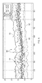
- the underlying trend of the data may be tracked. This can be seen in Figure 1 .
- the present invention provides a monitor and method to identify abnormalities in a system that seeks to address the aforementioned problems.
- the present invention provides a monitor to identify an abnormality in a system, the monitor comprising:
- the monitor identifies abnormalities of the system to be monitored. It tracks the behaviour of the parameter being measured so that abnormalities do not affect the thresholds but that underlying trends do affect the thresholds.
- the monitor may be a system health monitor.
- the processor may calculate the threshold by applying Bayesian extreme value theory to the parameter values stored in the buffer store. Alternatively the processor may calculate the threshold by determining an offset from the system state of the parameter values in the buffer store.
- the threshold calculated is strongly related to the parameter values in the buffer store.
- the estimator may estimate the next parameter value by applying a Kalman filter to the system state at the previous parameter value. Alternatively the estimator may estimate the next parameter value by calculating a running average or by applying a data smoothing technique.
- the estimate of the next parameter value is based on the parameter values in the buffer store so it is similar to previous values.
- the present invention also provides a method to identify an abnormality in a system, the method comprising iterating steps to:
- the threshold is unchanged by an identified parameter abnormality and subsequent abnormalities of the system are identified.
- Step b) may comprise selecting consecutive parameter values from the data series. Alternatively it may comprise selecting non-consecutive parameter values. Step b) may comprise selecting between ten and twenty parameter values from the data series.
- Step c) may comprise applying Bayesian extreme value theory to the parameter values in the buffer. Alternatively it may comprise determining an offset from the system state of the parameter values in the buffer.
- the threshold calculated at step c) is strongly related to the parameter values in the buffer.
- Step e)ii) may comprise applying a Kalman filter to the system state at the previous parameter value.
- step e)ii) may comprise calculating a running average or by applying a data smoothing technique to the parameter values in the buffer.
- the estimate of the next parameter value in the data series is based on the parameter values in the buffer so it is similar to previous values.
- the method may comprise a further step to report the parameter abnormality.
- a further step to report the parameter abnormality.
- the method may comprise a further step to report an abnormality of the system after three parameter abnormalities have been recorded at step e)ii).
- the method may comprise a further step to report an abnormality of the system after two parameter abnormalities have been recorded at step e)ii) or after more than three parameter abnormalities have been recorded at step e)ii).
- this reduces the probability of reporting an abnormality of the system as a result of a single, spurious parameter abnormality.
- Reporting an abnormality of the system may be in addition to reporting a parameter abnormality.
- the Kalman filter may apply a constant multiplier to the system state.
- the Kalman filter may apply a multiplier to the system state that is a function of at least one previous system state.
- the Kalman filter may comprise a noise component to accommodate random fluctuation in the parameter values.
- the Kalman filter may be a fixed or dynamic multiplier from the system state based on the parameter values in the buffer.
- the parameter may be measured at predetermined time intervals to form a time series of parameter values.
- the parameter may be a system parameter which is measured at a predefined frequency for other purposes or may be a system parameter measured only to identify parameter abnormalities from which an abnormality of the system can be determined.
- the system may comprise an engine.
- the system may comprise a gas turbine engine.
- the parameter may comprise one of the group comprising a component temperature; air temperature; oil temperature; a pressure; a shaft speed; vibration; clearance between components.
- Advantageously many or all of these parameters are measured for other reasons and so the monitor and method do not add weight or complexity to such an engine.
- the abnormality of the system may comprise one or more of the group comprising: overspeed of a rotating part of the engine; underspeed of a rotating part of the engine; system overheat; inadequate power output; failure of a rotating part of the engine.
- Such abnormalities of the system should be identified quickly and accurately in order for preventative or mitigation actions to be performed.
- the system may comprise a weather system.
- the parameter may comprise one of the group comprising air temperature; rainfall; wind speed; pressure; air flow.
- Advantageously abnormalities of such parameters may provide early indications of severe weather events such as storms, flooding, typhoons, hurricanes, and tornados.
- Step a) may comprise periodically measuring more than one parameter of the system and the steps of the method are performed for each parameter.
- the method may comprise a further step to report an abnormality of the system if a parameter abnormality is recorded for each parameter at step e)ii).
- this increases the certainty of a particular abnormality of the system.
- the method may comprise a further step to modify the system in response to a recorded parameter abnormality or in response to a reported abnormality in the system.
- the step of modifying the system may comprise one or more of the group comprising: inspecting a component of the system; testing a component of the system; cleaning a component of the system; performing maintenance actions on a component of the system; repairing a component of the system; replacing a component of the system; inspecting the system; testing the system; cleaning the system; performing maintenance actions on the system; repairing the system; removing the system from service.
- the present invention also provides a system health monitor configured to perform the steps of the method as described above; a computer program having instructions adapted to carry out the method as described above; a computer readable medium, having a computer program recorded thereon, wherein the computer program is adapted to make the computer execute the method as described above; a computer program comprising the computer readable medium as described.
- the present invention is initially described in relation to the health of a gas turbine engine 10. Other systems to which the monitor can be applied are described later.
- a gas turbine engine 10 is shown in Figure 2 and comprises an air intake 12 and a propulsive fan 14 that generates two airflows A and B.
- the gas turbine engine 10 comprises, in axial flow A, an intermediate pressure compressor 16, a high pressure compressor 18, a combustor 20, a high pressure turbine 22, an intermediate pressure turbine 24, a low pressure turbine 26 and an exhaust nozzle 28.
- the high pressure turbine 22 and high pressure compressor 18 are coupled by a high pressure shaft
- the intermediate pressure turbine 24 and intermediate pressure compressor 16 are coupled by an intermediate pressure shaft
- the low pressure turbine 26 is coupled to the fan 14 by a low pressure shaft.
- a nacelle 30 surrounds the gas turbine engine 10 and defines, in axial flow B, a bypass duct 32.
- Engine health monitoring typically includes monitoring engine parameters to identify an isolated exceedance relative to a threshold, prolonged periods outside predefined limits, rate of change of the parameter greater than a predefined rate, and underlying trends indicating deterioration. More complex relationships between two or more parameters may also be used to indicate changes in the health of an engine.
- Typical engine faults, anomalies or abnormalities that may be detected or predicted by engine health monitoring include overspeed or underspeed of a rotational shaft of the engine 10, overheating of one or more components of the engine 10, excessive vibration, pressure fluctuations or asymmetries that may result in surge or stall conditions, increased component clearances which reduce efficiency, and many other conditions that are apparent to the skilled reader.
- a plurality of sensors are mounted to various engine components to measure operational parameters such as temperature, velocity, flow rate, rotational speed, torque, distance, stress or deflection within the engine 10 or one or more of its components. Such parameters may be measured at prescribed time increments or at predetermined equipment states during operation and stored for communication to a monitoring unit which may be located on a vehicle, such as an aircraft powered by the gas turbine engine 10, or which may be located remotely.
- a significant volume of data may be amassed during operation of the engine 10, which is processed to determine existing or predicted faults.
- the resulting fault information may be communicated to an organisation, entity or division responsible for supporting, maintaining or designing the equipment such that it can be taken into account within a planning process for equipment maintenance, scheduling, operational planning or equipment improvement by way of design changes or modifications.
- Figure 3 schematically illustrates a monitor to identify an abnormality in a system according to the present invention.
- a sensor 60 is provided to measure a parameter value of the system.
- the sensor 60 may be a speed sensor to measure the rotational speed of one of the high pressure, intermediate pressure and low pressure shafts.
- the sensor 60 may alternatively be a temperature sensor arranged to measure a component temperature or the temperature of the airflow through the engine 10 at a specific point in the engine 10, for example in the intermediate pressure compressor 16.
- the sensor 60 may alternatively be a pressure sensor arranged to measure the pressure of the airflow through the engine 10 at a specific point in the engine 10, for example in the intermediate pressure compressor 16. Any other sensor 60 measuring any other parameter of the engine 10 from which an abnormality of that engine can be derived may be used instead.
- the measured parameter values may be stored in memory for real-time control functions and for detailed off-line analysis.
- a subset of the parameter values measured by the sensor 60 is stored in a buffer store 62.
- the buffer 62 may be sized to hold, for example, ten to twenty parameter values.
- a processor 64 receives the parameter values in the buffer store 62 and uses them to calculate a threshold 66 using Bayesian extreme value theory as will be discussed below.
- the threshold 66 is supplied to a comparator 68.
- the current measured parameter value is also supplied to the comparator 68 from the sensor 60 for comparison against the calculated threshold 66.
- the measured parameter value is passed from the comparator 68 along line 70 to the buffer store 62. This measured parameter value is therefore available for the processor 64 to use in calculating the next threshold 66.
- the comparator 68 passes the measured parameter value along lines 72 and 74.
- Line 72 leads to a recorder 76 which records that measured parameter value as a parameter abnormality.
- a reporter 78 may be provided to receive the parameter abnormality from the recorder 76 and to report the parameter abnormality to personnel or another system for verification or system modification actions.
- Line 74 leads to an estimator 80 which estimates the parameter value on the basis of the parameter values currently in the buffer 62.
- the estimator 80 applies a Kalman filter to these values to calculate the estimated parameter value 82, which therefore does not exceed the calculated threshold 66.
- This estimated parameter value 82 is then passed to the buffer store 62 instead of the measured parameter value. This ensures that the buffer 62 comprises only normal parameter values so that subsequent calculated thresholds 66 are not premised on abnormal parameter values.
- a subset of these parameter values is then selected at the step 36.
- the subset is stored in the buffer store 62 at the step 38.
- the subset may comprise all the measured parameter values. Subsequently there will be more measured parameter values than can be held in the buffer 62, as will be described, so that a subset is required.
- the subset may be any requisite number of available parameter values.
- the subset will be the most recent parameter values, for example the last ten parameter values that have been measured.
- the processor 64 is used to calculate a threshold 66 that corresponds to the boundary between normal and abnormal values of the parameter.
- the threshold 66 is calculated by applying Bayesian extreme value theory to the subset of parameter values stored in the buffer 62. Bayesian extreme value theory builds an extreme value distribution using few data points, as is well understood. Ordinarily there is an upper threshold and a lower threshold, which bound the range of normal values for the measured parameter.
- the thresholds 66 can be set in terms of a multiple of the standard deviation away from the mean value. The upper and lower thresholds may be the same multiple of the standard deviation or different multiples. Generating such thresholds 66 using Bayesian extreme value theory is taught in US7925470 which is incorporated herein by reference.
- the threshold relating to minimum clearance may be closer to the mean of the parameter values than the threshold relating to the maximum clearance because if the minimum clearance is exceeded the rotor blade tips may rub against the casing thereby permanently changing the spacing between them, whereas if the maximum clearance is exceeded the effect is primarily on efficiency and is reversible.
- step 42 the next value of the parameter is measured and recorded.
- the measured parameter value is compared to the threshold 66, step 44, in the comparator 68. If the measured parameter value does not exceed the threshold 66, the measurement is added to the buffer 62 on iteration branch 46. Where the buffer 62 is full, that is there is a parameter value in each available slot, a previous parameter value is removed from the buffer 62 and the measurement is added into the buffer 62 instead. For example, where the parameter is measured as a time series, the oldest parameter value in the buffer 62 may be removed and the measurement taken at step 42 be added to the buffer 62 instead.
- the branch 48 is followed.
- the measurement is deemed to be a parameter abnormality and is recorded as such by the recorder 76 at step 50.
- the next (n+1) parameter value is estimated at step 52 using the estimator 80.
- the estimated parameter value 82 is calculated by applying a Kalman filter to the system state of the current parameter values in the buffer store 62.
- the mean and standard deviation of the parameter values in the buffer 62 are multiplied by a multiplier to give an iteration loop update, for example a time step update, of the mean and standard deviation.
- the multiplier may be a constant multiplier.
- the multiplier may be functionally dependent on one or more previous system states. Thus the multiplier may be configured to follow the trend of previous mean values.
- the Kalman filter may also add a noise element. The noise element may be added after the multiplier is applied.
- the mean and standard deviation of the current parameter values in the buffer 62 are expressed as a matrix and the multiplier is a state transition matrix.
- the multiplier is a state transition matrix.
- the estimated parameter value 82 is then added to the buffer store 62 via feedback loop 54. As discussed above, if the buffer 62 is already full the estimated parameter value 82 displaces a parameter value already in the buffer 62. For example the oldest parameter value in the buffer 62 may be removed and the estimated parameter value 82 added into the buffer 62 instead.
- adding the estimated parameter value 82 to the buffer 62 instead of the measured parameter value, where the measured parameter value exceeds the calculated threshold 66 results in all parameter values in the buffer 62 being within the 'normal' parameter value range so that subsequently calculated thresholds 66 remain appropriate. The method then repeats from step 40 using the new contents of the buffer 62.
- the recorded parameter abnormality is reported.
- the step 56 may not report each parameter abnormality but may report once a predetermined number of parameter abnormalities have been recorded at step 50.
- reporting at step 56 may occur when three consecutive parameter abnormalities have been recorded at step 50.
- reporting at step 56 may occur when three parameter abnormalities have been recorded at step 50 within the previous five iterations of the method.
- reporting parameter abnormalities only when more than one has occurred within a predetermined iteration constraint reduces the incidence of false reporting whilst not delaying the reporting significantly. Reporting preferably occurs in parallel to a subsequent iteration of the method.
- the parameter abnormality may be reported at step 56 with a confidence level or indication of risk.
- the confidence level may relate to the probability that the reported parameter abnormality is incorrect.
- the confidence level may increase where more consecutive parameter abnormalities have been reported at step 50.
- the indication of risk may relate to the risk associated with not taking action on the basis of the reported parameter abnormality.
- the reporting step 56 may take the form of providing an alert to the system operator.
- the alert may also include recommended further actions, such as inspection or testing of components or the system, cleaning of components or the system, performing maintenance actions on components or the system, repairing components or the system, replacing components of the system, or removing the system from service.
- a further optional step 58 comprises reporting an abnormality of the system.
- a system abnormality is directly correlated with an abnormality of a single parameter, such as turbine gas temperature
- this reporting step 58 may occur with or immediately after the step 56 of reporting the parameter abnormality.
- Other system abnormalities such as turbine wear or failure, compressor failure or similar, may be dependent on abnormalities in more than one parameter.
- the method can be performed, in series or parallel, for two or more parameters of the system.
- the reporting step 58 can then be triggered by recorded parameter abnormalities in each relevant parameter.
- the system abnormalities may be reported at step 58 with a confidence level or indication of risk.
- the confidence level may relate to the probability that the reported system abnormality is correct.
- the confidence level may increase where more consecutive parameter abnormalities have been reported.
- the indication of risk may relate to the risk associated with not taking action on the basis of the reported system abnormality.
- Such modification may be automatic, such as applying a trim to the parameter to return measured parameters to within the bounds of normal values, or may be manual, such as inspection, testing, or maintenance activities.
- Figure 5 and Figure 6 show the parameter values measured in successive measurement steps over time.
- the y-axis is the magnitude of the measurements with an exemplary scale showing the change in the parameter value.
- the y-axis may be delta turbine gas temperature, that is the change in turbine gas temperature.
- the parameter values are plotted as points 84.
- the mean value of the parameter values in the buffer 62 is plotted as line 86. As is apparent, the mean line 86 varies comparatively slowly over time even when there are significantly abnormal parameter values, such as those indicated at 88.
- the upper threshold 90 and lower threshold 92 are plotted a defined multiple of the standard deviation away from the mean 86.
- the upper threshold 90 is the same multiple of standard deviation away from the mean as the lower threshold 92.
- the upper threshold 90 and lower threshold 92 will be different distances away from the mean, because they will be calculated as different multiples of the standard deviation from the mean line 86.
- the upper threshold 90 and lower threshold 92 track the underlying trend of the parameter values 84 but still effectively differentiate between normal and abnormal 88 parameter values.
- clusters of abnormal parameter values 88 either consecutive or in close proximity with one or two normal parameter values between pairs of abnormal parameter values 88, these are correctly identified as parameter abnormalities by the monitor and method of the present invention.
- This can be contrasted to the prior art plot in Figure 1 where only the first of a cluster of large parameter values is identified as an abnormality because the thresholds incorporate that value and thus exceed subsequent parameter values of similar magnitude.
- the system to be monitored by the present invention has been described as a gas turbine engine 10 the present invention is applicable to many other systems.
- the system may be an internal combustion engine, a steam turbine, a wind turbine or a tidal turbine.
- the measured parameter for such engines may be a shaft speed, blade tip speed, clearance, vibration, fluid temperature, pressure, power output or displacement.
- the system abnormality may be overspeed or underspeed of a rotating part of the engine, system overheat or inadequate power output.
- the system may be a machine, such as a manufacturing machine, lathe, turning machine, drill, material deposition machine or welding machine.
- the measured parameter for such machines may be a shaft speed, vibration, pressure, displacement, temperature of a component being worked or of the system components, layer thickness or weld integrity.
- the system abnormality may be misalignment of parts of the machine, insufficient pressure or speed to achieve the manufacturing task or blocked material deposition nozzles.
- the monitored system may be a network of pieces of equipment.
- it may be a power plant comprising a gas turbine engine 10, pumps, tanks, filters, controllers and interconnecting pipework.
- the measured parameter may include flow rates, flow pressures, fluid temperatures, and pump output power.
- the system abnormalities may include flow reduction, filtration reduction or overheating.
- the system monitored by the present invention may alternatively be a weather system.
- the measured parameter may be air temperature, air pressure, rainfall, wind speed, or water levels in rivers or lakes.
- the system abnormalities may include floods, droughts and hurricanes.
- the measured values of the parameter may be processed before being passed to the processor 64 or before the step of storing the values in the buffer 62, step 38.
- the measured values may be normalised or corrected for thermal effects.
- the threshold 66 may alternatively be calculated as an offset from the estimate of the state.
- the threshold 66 may be set at three times the standard deviation, referred to as three sigma (3 ⁇ ), from the state estimate.
- the estimator 80 has been described as applying a Kalman filter to estimate the parameter value because this is mathematically optimal. However, it may alternatively be a running average or other data smoothing method.
- the monitor and method of the present invention is preferably encompassed in computer-implemented code and stored on a computer-readable medium. It is thus a computer-implemented monitor and a computer-implemented method to identify an abnormality in a system.
- the method may be implemented on a basic computer system comprising a processing unit, memory, user interface means such as a keyboard and/or mouse, and display means.
- the method may be performed 'offline' on data which has been measured and recorded previously. Alternatively it may be performed in 'real-time', that is at the same time that the data is measured.
- the computer may be coupled to the system. Where the system is or forms part of a gas turbine engine 10 the computer may be an electronic engine controller or another on-board processor. Where the gas turbine engine 10 powers an aircraft, the computer may be an engine controller, a processor on-board the engine 10 or a processor on-board the aircraft.
Landscapes
- Engineering & Computer Science (AREA)
- Physics & Mathematics (AREA)
- General Physics & Mathematics (AREA)
- Data Mining & Analysis (AREA)
- Theoretical Computer Science (AREA)
- General Engineering & Computer Science (AREA)
- Life Sciences & Earth Sciences (AREA)
- Bioinformatics & Cheminformatics (AREA)
- Bioinformatics & Computational Biology (AREA)
- Evolutionary Biology (AREA)
- Combustion & Propulsion (AREA)
- Chemical & Material Sciences (AREA)
- Artificial Intelligence (AREA)
- Probability & Statistics with Applications (AREA)
- Pure & Applied Mathematics (AREA)
- Automation & Control Theory (AREA)
- Mathematical Physics (AREA)
- Evolutionary Computation (AREA)
- Computer Vision & Pattern Recognition (AREA)
- Mathematical Optimization (AREA)
- Mathematical Analysis (AREA)
- Computational Mathematics (AREA)
- Databases & Information Systems (AREA)
- Software Systems (AREA)
- Operations Research (AREA)
- Algebra (AREA)
- Mechanical Engineering (AREA)
- Testing And Monitoring For Control Systems (AREA)
- Testing Of Devices, Machine Parts, Or Other Structures Thereof (AREA)
- Testing Or Calibration Of Command Recording Devices (AREA)
- Test And Diagnosis Of Digital Computers (AREA)
Applications Claiming Priority (1)
| Application Number | Priority Date | Filing Date | Title |
|---|---|---|---|
| GB201322062A GB201322062D0 (en) | 2013-12-13 | 2013-12-13 | System abnormalities |
Publications (2)
| Publication Number | Publication Date |
|---|---|
| EP2884404A2 true EP2884404A2 (de) | 2015-06-17 |
| EP2884404A3 EP2884404A3 (de) | 2015-07-22 |
Family
ID=50030880
Family Applications (1)
| Application Number | Title | Priority Date | Filing Date |
|---|---|---|---|
| EP14194647.5A Withdrawn EP2884404A3 (de) | 2013-12-13 | 2014-11-25 | Systemabnormalitäten |
Country Status (4)
| Country | Link |
|---|---|
| US (1) | US20150168264A1 (de) |
| EP (1) | EP2884404A3 (de) |
| CA (1) | CA2874449A1 (de) |
| GB (1) | GB201322062D0 (de) |
Cited By (3)
| Publication number | Priority date | Publication date | Assignee | Title |
|---|---|---|---|---|
| EP3217243A1 (de) * | 2016-03-10 | 2017-09-13 | Simmonds Precision Products, Inc. | Fehlerdiagnose für physikalische komponente |
| EP3287860A1 (de) * | 2016-08-22 | 2018-02-28 | The Boeing Company | Thermischer ereignisindikator für ein flugzeugtriebwerk |
| EP3671175A4 (de) * | 2018-02-27 | 2020-12-16 | Mitsubishi Heavy Industries Marine Machinery & Equipment Co., Ltd. | Zustandsdiagnosevorrichtung, zustandsdiagnoseverfahren und zustandsdiagnoseprogramm |
Families Citing this family (10)
| Publication number | Priority date | Publication date | Assignee | Title |
|---|---|---|---|---|
| US20150159349A1 (en) * | 2015-02-16 | 2015-06-11 | Caterpillar Inc. | Lubricant testing assembly |
| US9885250B2 (en) * | 2015-10-23 | 2018-02-06 | United Technologies Corporation | Autonomous engine health management system |
| US10316689B2 (en) | 2016-08-22 | 2019-06-11 | Rolls-Royce Corporation | Gas turbine engine health monitoring system with shaft-twist sensors |
| NL2019940B1 (en) * | 2017-11-20 | 2019-05-24 | Micro Turbine Tech B V | Micro gas turbine designed to limit heat losses therefrom |
| BE1028135B1 (nl) * | 2020-03-10 | 2021-10-11 | Atlas Copco Airpower Nv | Werkwijze en inrichting voor het regelen van de pompsnelheid, computerprogramma en een door een computer leesbaar medium waarop het computerprogramma is opgeslagen daarbij toegepast en een pomp |
| CN112650281B (zh) * | 2020-12-14 | 2023-08-22 | 一飞(海南)科技有限公司 | 多传感器三余度系统、控制方法、无人机、介质及终端 |
| CN114323664A (zh) * | 2021-12-13 | 2022-04-12 | 中国船舶重工集团公司第七0三研究所 | 一种燃气轮机燃气振动异常的检测方法 |
| DE102022134209B3 (de) | 2022-12-20 | 2024-05-16 | Rolls-Royce Solutions GmbH | Verfahren, Diagnoseeinrichtung und System zum Überwachen eines Betriebs einer Brennkraftmaschine |
| WO2025015356A1 (de) * | 2023-07-19 | 2025-01-23 | Engel Austria Gmbh | Verfahren und vorrichtung zum überwachen einer produktionsanlage |
| FR3152542A1 (fr) * | 2023-09-01 | 2025-03-07 | Safran Aircraft Engines | Procédé de configuration d’un module pour la détection de commutation d’une vanne d’un circuit de circulation d’huile |
Family Cites Families (2)
| Publication number | Priority date | Publication date | Assignee | Title |
|---|---|---|---|---|
| US20080154473A1 (en) * | 2006-12-22 | 2008-06-26 | United Technologies Corporation | Gas turbine engine performance data validation |
| US20090043447A1 (en) * | 2007-08-07 | 2009-02-12 | General Electric Company | Systems and Methods for Model-Based Sensor Fault Detection and Isolation |
-
2013
- 2013-12-13 GB GB201322062A patent/GB201322062D0/en not_active Ceased
-
2014
- 2014-11-25 EP EP14194647.5A patent/EP2884404A3/de not_active Withdrawn
- 2014-11-26 US US14/554,465 patent/US20150168264A1/en not_active Abandoned
- 2014-12-12 CA CA2874449A patent/CA2874449A1/en not_active Abandoned
Cited By (6)
| Publication number | Priority date | Publication date | Assignee | Title |
|---|---|---|---|---|
| EP3217243A1 (de) * | 2016-03-10 | 2017-09-13 | Simmonds Precision Products, Inc. | Fehlerdiagnose für physikalische komponente |
| US20170261406A1 (en) * | 2016-03-10 | 2017-09-14 | Simmonds Precision Products, Inc. | Physical component fault diagnostics |
| EP3287860A1 (de) * | 2016-08-22 | 2018-02-28 | The Boeing Company | Thermischer ereignisindikator für ein flugzeugtriebwerk |
| CN107767612A (zh) * | 2016-08-22 | 2018-03-06 | 波音公司 | 用于飞行器发动机的热事件指示器 |
| US10151643B2 (en) | 2016-08-22 | 2018-12-11 | The Boeing Company | Thermal event indicator for aircraft engine |
| EP3671175A4 (de) * | 2018-02-27 | 2020-12-16 | Mitsubishi Heavy Industries Marine Machinery & Equipment Co., Ltd. | Zustandsdiagnosevorrichtung, zustandsdiagnoseverfahren und zustandsdiagnoseprogramm |
Also Published As
| Publication number | Publication date |
|---|---|
| US20150168264A1 (en) | 2015-06-18 |
| CA2874449A1 (en) | 2015-06-13 |
| GB201322062D0 (en) | 2014-01-29 |
| EP2884404A3 (de) | 2015-07-22 |
Similar Documents
| Publication | Publication Date | Title |
|---|---|---|
| EP2884404A2 (de) | Systemabnormalitäten | |
| RU2468212C2 (ru) | Система и способ для обнаружения смещения базового значения эксцентриситета ротора | |
| JP4149899B2 (ja) | システム上で診断を行うための方法 | |
| CN101268429B (zh) | 监控衰退系统 | |
| CN108062428B (zh) | 一种涡扇发动机在线部件故障诊断方法及系统 | |
| US6208953B1 (en) | Method for monitoring plants with mechanical components | |
| CN110008565B (zh) | 基于运行参数关联性分析的工业过程异常工况预测方法 | |
| CN108732962B (zh) | 压缩机水洗规划 | |
| EP2740916B1 (de) | Betriebsstützsysteme und verfahren zum berechnen und bewerten von turbinentemperaturen und -gesundheit | |
| US12276567B2 (en) | Method and system for monitoring a status of a reducer of a gas turbine | |
| EP1811133A2 (de) | Sensordiagnose mittels eines Qualitätsparametermodells | |
| US20020052712A1 (en) | Method for the monitoring of a plant | |
| EP2559863A2 (de) | Verfahren und System zur Analyse von Turbomaschinen | |
| Panov | Auto-tuning of real-time dynamic gas turbine models | |
| US8869603B2 (en) | Debris detection in turbomachinery and gas turbine engines | |
| CN108223137A (zh) | 燃气涡轮发动机机队性能劣化 | |
| EP3875774B1 (de) | Systeme, programmprodukte und verfahren zur einstellung des betriebsgrenzwerts (ol) für kompressoren von gasturbinensystemen basierend auf dem massenstromverlust | |
| EP3936957B1 (de) | Fehlerbasiertes verfahren zur berechnung einer restlebensdauer einer vorrichtung | |
| US10400624B2 (en) | System and method for planning engine borescope inspections based on FOD probability estimation | |
| JP6803788B2 (ja) | 情報処理装置、情報処理方法およびプログラム | |
| EP3589843A1 (de) | Verfahren und vorrichtung zum bestimmen eines indikators für eine vorhersage einer instabilität in einem verdichter sowie verwendung | |
| EP2469098A1 (de) | Verfahren und vorrichtung zur vorhersage der instabilität eines axialkompressors | |
| JP7471983B2 (ja) | 状態監視装置および状態監視方法 | |
| KR102775770B1 (ko) | 균열들을 확인하기 위한 터빈 블레이드 상태 모니터링 시스템 | |
| CN113039360B (zh) | 用于对风力涡轮机的运行参数进行监测的方法和风力涡轮机监测系统 |
Legal Events
| Date | Code | Title | Description |
|---|---|---|---|
| PUAI | Public reference made under article 153(3) epc to a published international application that has entered the european phase |
Free format text: ORIGINAL CODE: 0009012 |
|
| 17P | Request for examination filed |
Effective date: 20141125 |
|
| AK | Designated contracting states |
Kind code of ref document: A2 Designated state(s): AL AT BE BG CH CY CZ DE DK EE ES FI FR GB GR HR HU IE IS IT LI LT LU LV MC MK MT NL NO PL PT RO RS SE SI SK SM TR |
|
| AX | Request for extension of the european patent |
Extension state: BA ME |
|
| PUAL | Search report despatched |
Free format text: ORIGINAL CODE: 0009013 |
|
| AK | Designated contracting states |
Kind code of ref document: A3 Designated state(s): AL AT BE BG CH CY CZ DE DK EE ES FI FR GB GR HR HU IE IS IT LI LT LU LV MC MK MT NL NO PL PT RO RS SE SI SK SM TR |
|
| AX | Request for extension of the european patent |
Extension state: BA ME |
|
| RIC1 | Information provided on ipc code assigned before grant |
Ipc: G05B 23/02 20060101ALI20150617BHEP Ipc: G06K 9/00 20060101ALI20150617BHEP Ipc: F02C 9/00 20060101ALI20150617BHEP Ipc: G06F 17/18 20060101AFI20150617BHEP |
|
| STAA | Information on the status of an ep patent application or granted ep patent |
Free format text: STATUS: THE APPLICATION IS DEEMED TO BE WITHDRAWN |
|
| 18D | Application deemed to be withdrawn |
Effective date: 20160123 |