EP2884517A1 - Contact AMF pour interrupteur à vide avec élément de renforcement - Google Patents
Contact AMF pour interrupteur à vide avec élément de renforcement Download PDFInfo
- Publication number
- EP2884517A1 EP2884517A1 EP13005772.2A EP13005772A EP2884517A1 EP 2884517 A1 EP2884517 A1 EP 2884517A1 EP 13005772 A EP13005772 A EP 13005772A EP 2884517 A1 EP2884517 A1 EP 2884517A1
- Authority
- EP
- European Patent Office
- Prior art keywords
- rod
- bottom plate
- amf
- electrode
- insulating
- Prior art date
- Legal status (The legal status is an assumption and is not a legal conclusion. Google has not performed a legal analysis and makes no representation as to the accuracy of the status listed.)
- Withdrawn
Links
- MCMNRKCIXSYSNV-UHFFFAOYSA-N Zirconium dioxide Chemical compound O=[Zr]=O MCMNRKCIXSYSNV-UHFFFAOYSA-N 0.000 claims description 12
- 239000000463 material Substances 0.000 claims description 12
- 239000011810 insulating material Substances 0.000 claims description 11
- 239000000919 ceramic Substances 0.000 claims description 9
- 229910052751 metal Inorganic materials 0.000 claims description 9
- 239000002184 metal Substances 0.000 claims description 9
- 238000002161 passivation Methods 0.000 claims description 5
- 239000012671 ceramic insulating material Substances 0.000 claims description 2
- 238000000576 coating method Methods 0.000 description 7
- 239000011248 coating agent Substances 0.000 description 6
- 229910001220 stainless steel Inorganic materials 0.000 description 6
- 239000010935 stainless steel Substances 0.000 description 6
- PNEYBMLMFCGWSK-UHFFFAOYSA-N aluminium oxide Inorganic materials [O-2].[O-2].[O-2].[Al+3].[Al+3] PNEYBMLMFCGWSK-UHFFFAOYSA-N 0.000 description 4
- 230000006835 compression Effects 0.000 description 4
- 238000007906 compression Methods 0.000 description 4
- 229910010293 ceramic material Inorganic materials 0.000 description 3
- 229910052593 corundum Inorganic materials 0.000 description 3
- 230000002787 reinforcement Effects 0.000 description 3
- 229910001845 yogo sapphire Inorganic materials 0.000 description 3
- 229910052727 yttrium Inorganic materials 0.000 description 3
- VWQVUPCCIRVNHF-UHFFFAOYSA-N yttrium atom Chemical compound [Y] VWQVUPCCIRVNHF-UHFFFAOYSA-N 0.000 description 3
- RYGMFSIKBFXOCR-UHFFFAOYSA-N Copper Chemical compound [Cu] RYGMFSIKBFXOCR-UHFFFAOYSA-N 0.000 description 1
- 229910052581 Si3N4 Inorganic materials 0.000 description 1
- 230000005540 biological transmission Effects 0.000 description 1
- 230000015572 biosynthetic process Effects 0.000 description 1
- 239000004020 conductor Substances 0.000 description 1
- 238000010276 construction Methods 0.000 description 1
- 229910052802 copper Inorganic materials 0.000 description 1
- 239000010949 copper Substances 0.000 description 1
- 238000007872 degassing Methods 0.000 description 1
- 230000008021 deposition Effects 0.000 description 1
- 238000000151 deposition Methods 0.000 description 1
- 238000009413 insulation Methods 0.000 description 1
- 239000012212 insulator Substances 0.000 description 1
- 239000007769 metal material Substances 0.000 description 1
- 150000002739 metals Chemical class 0.000 description 1
- 238000000034 method Methods 0.000 description 1
- 239000011859 microparticle Substances 0.000 description 1
- 238000007750 plasma spraying Methods 0.000 description 1
- 238000000623 plasma-assisted chemical vapour deposition Methods 0.000 description 1
- 230000035939 shock Effects 0.000 description 1
Images




Classifications
-
- H—ELECTRICITY
- H01—ELECTRIC ELEMENTS
- H01H—ELECTRIC SWITCHES; RELAYS; SELECTORS; EMERGENCY PROTECTIVE DEVICES
- H01H33/00—High-tension or heavy-current switches with arc-extinguishing or arc-preventing means
- H01H33/60—Switches wherein the means for extinguishing or preventing the arc do not include separate means for obtaining or increasing flow of arc-extinguishing fluid
- H01H33/66—Vacuum switches
- H01H33/664—Contacts; Arc-extinguishing means, e.g. arcing rings
- H01H33/6642—Contacts; Arc-extinguishing means, e.g. arcing rings having cup-shaped contacts, the cylindrical wall of which being provided with inclined slits to form a coil
-
- H—ELECTRICITY
- H01—ELECTRIC ELEMENTS
- H01H—ELECTRIC SWITCHES; RELAYS; SELECTORS; EMERGENCY PROTECTIVE DEVICES
- H01H33/00—High-tension or heavy-current switches with arc-extinguishing or arc-preventing means
- H01H33/60—Switches wherein the means for extinguishing or preventing the arc do not include separate means for obtaining or increasing flow of arc-extinguishing fluid
- H01H33/66—Vacuum switches
- H01H33/664—Contacts; Arc-extinguishing means, e.g. arcing rings
- H01H2033/6648—Contacts containing flexible parts, e.g. to improve contact pressure
-
- H—ELECTRICITY
- H01—ELECTRIC ELEMENTS
- H01H—ELECTRIC SWITCHES; RELAYS; SELECTORS; EMERGENCY PROTECTIVE DEVICES
- H01H3/00—Mechanisms for operating contacts
- H01H3/001—Means for preventing or breaking contact-welding
Definitions
- the invention relates to an AMF contact for vacuum interrupter, with concentric opposing contact pieces, wherein the contact pieces consist of an external electrode shaped like a coil an generating a strong axial magnetic field, and an inner internal electrode, carrying the nominal current, according to the preamble of claim 1.
- FR 2 946 791-A1 discloses a mechanical reinforcement rod located between the electrode and the bottom support plate of a "standard” AMF electrode; "standard” means single electrode contact. According to that, the rod has a high electrical resistivity so that a negligible current flows through it in comparison to the current flowing into the coil. Furthermore is mentioned in this state of the art document, that the rod can be composed of a hollow metallic tube filled by a ceramic material.
- the rod is there to reinforce mechanically the electrode in order to avoid the collapse of the top part during closing operations.
- This technical application goes in the direction of generator circuit- or high voltage breaker, where a large diameter of electrode is necessary to interrupt the fault current.
- the functionality aim, and therefore the object of the invention is the opposite, i.e. to provide a mechanical reinforcement solution in case of opening and breaking of the weld.
- a rod which is at one end fixed at that lower side of the top electrode and the other end of the rod is guided trough an opening of the bottom plate, wherein at that end of the rod the rod is being furnished with an extended head in such, that the extended head of the rod locks or tightens the rod in a defined axial position.
- the opening in the bottom plate is in relation to the diameter of the rod dimensioned in such, that the opening allows the rod a free sliding through it. This is important, to impact forces into the top electrode, in order to impact a force transmission of a compression or a tension force to the top electrode.
- the axial position is variable, in such, that a pre-compression- or pre-tension force can be impacted on the top electrode via the rod, especially the axial rod position.
- the rod is made of an insulating material or a material with low electrical conductivity.
- the rod is made of a metal core with an insulting surface passivation.
- the AMF or also the TMF (especially cup shaped) standard contact system are reinforced by the use of the pin between the upper and the bottom plate of the contact part.
- the insulating surface passivation is made of ceramic.
- the ceramic insulating material can be made of the base of AL2O3, ZrO2, Y203. These ceramics have a high mechanical withstand as well as they are non-conductive.
- a further advantageous embodiment in use of a metal rod is, that the outer diameter of the rod is dimensioned relatively to the inner diameter of the opening in the bottom plate in such, that it leaves an insulating ring space between the outer surface of the rod and the inner surface of the opening, and that the head of the rod is isolated against the bottom plate by a washer made of insulating material.
- a screw or a rod made of an insulating or relatively low electrical conductivity material which is fixed (screwed or brazed) to the top electrode, and whose head can slide freely when the top electrode is compressed, but acts as a counter-force when the top electrode is subject to a tension force, like a weld force for instance, like shown in figure 2 .
- the metallic pin part can be fixed arranged between the bottom part of the contact system and the contact plate but will be coated or covered by the describt ceramic layer.
- a relatively low electrical conductivity material is relative to the coil material. That is the case of stainless steel screw or rod for a copper coil, for instance.
- Typical insulating material includes ceramic material such as alumina, i.e. Al 2 O 3 which is adequate for vacuum application due to low degassing, or zirconia, i.e. ZrO 2 (Yttrium stabilized) which has high toughness properties to limit potential crack formation, Si 3 N 4 and possibly other insulating materials.
- Figure 2 shows in "A" a system acting in compression.
- the insulating or relatively low electrical conductivity screw/rod can move vertically without mechanical stresses, and for this design, the travel is maximum 1 mm.
- the screw or rod should made of material with good mechanical properties (yield strength) such as stainless steel, for instance.
- Typical coating insulating material can be Al 2 O 3 , ZrO 2 (Yttrium stabilized),etc.
- the coatings can be prepared by various deposition technics on stainless steel rod/screws or on other metals. Typical methods include plasma spraying, PVD, CVD, PECVD, etc.
- a further alternative is a hollow metal screw/rod filled in by a ceramic/relatively low electrical conductivity material, see figure 4 .
- This can also be an insulating material (ceramic) coated by a thin metallic layer like stainless steel for a few micro-meters.
- a further alternative is a metallic screw/rod with an insulating/relatively low electrical conductivity washer.
- the washer can be made of a metallic material coated with an insulator film such as ceramic materials (Al 2 O 3 , ZrO 2 (Yttrium stabilized), ).
- the "slide-through" hole must be large enough, so that the metallic screw/rod does not touch the side of the electrode, which would create a conductive path. See figure 5.
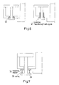
- Figure 5 shows a metallic screw/rod with an insulating/relatively low electrical conductivity washer interposed between the head of the screw and the bottom plate of the electrode.
- a metallic screw/rod with an insulating/relatively low electrical conductivity "feed-through" around the bottom plate separating electrically the screw/rod from the bottom plate, like shown in figure 6 .
- Figure 6 shows a metallic screw/rod with an insulating/relatively low electrical conductivity "feed-through" around the bottom plate of the electrode separating electrically the electrode from the screw/rod.
- the feed-through can be extended to guide the screw/rod (right drawing).
- the spring functionality would be to compensate mechanical playement in the mechanical construction and to absorb shocks, like shown in figure 7 .
- Figure 7 shows a metallic screw/rod with an insulating/relatively low electrical conductivity washer and a spring between the washer and the head of the screw.
- a Metallic screw/rod with an insulating/relatively low electrical conductivity section (here on top of the screw/rod).
- Special shapes, essentially in form of cones, for the head screw/rod and for the feed-through can be designed in order to minimize the mechanical stresses when the counter-force is applied, like shown in figure 9 . Other geometries can be possible too.
- Figure 9 shows illustrations of screw/rod with special head shapes (right), and different shapes of the "insulating/low electrical conductivity "feed-through”.
- a special add-on enclosing the screw/rod head is considered as a solution to capture possible micro-particles of the insulating/relatively low electrical conductivity material which can be lost by either friction on the electrode or by repeated mini-shocks compression.
- the solution is envisioned to keep the dielectric strength at high value, like shown in figure 10 .
- Figure 10 shows illustrations of an encapsulating add-on around the head of the screw/rod.
- Figure 11 shows a metallic rod with an insulating/relatively low conducting section (here on the top of the rod).
- Figure 12 shows a hollow metallic rod filled with an insulating/relatively low conducting material.
- a metallic ring thick enough ( ⁇ 5 mm) to sustain the tensile force (weld force).
- the metal is typically stainless steel or other high yield strength material.
- the ring In case of stainless steel electrode, the ring must have bored in order to reduce its electrical resistance to acceptable value, i.e. carrying less than 10% of nominal current.
- the ring can be shaped in order to produce an axial magnetic field as well.
Landscapes
- High-Tension Arc-Extinguishing Switches Without Spraying Means (AREA)
Priority Applications (3)
| Application Number | Priority Date | Filing Date | Title |
|---|---|---|---|
| EP13005772.2A EP2884517A1 (fr) | 2013-12-11 | 2013-12-11 | Contact AMF pour interrupteur à vide avec élément de renforcement |
| US14/567,582 US20150162150A1 (en) | 2013-12-11 | 2014-12-11 | Amf contact for vacuum interrupter with inforcement element |
| CN201410858236.9A CN104715963A (zh) | 2013-12-11 | 2014-12-11 | 具有加强元件的用于真空断路器的amf触头 |
Applications Claiming Priority (1)
| Application Number | Priority Date | Filing Date | Title |
|---|---|---|---|
| EP13005772.2A EP2884517A1 (fr) | 2013-12-11 | 2013-12-11 | Contact AMF pour interrupteur à vide avec élément de renforcement |
Publications (1)
| Publication Number | Publication Date |
|---|---|
| EP2884517A1 true EP2884517A1 (fr) | 2015-06-17 |
Family
ID=49876337
Family Applications (1)
| Application Number | Title | Priority Date | Filing Date |
|---|---|---|---|
| EP13005772.2A Withdrawn EP2884517A1 (fr) | 2013-12-11 | 2013-12-11 | Contact AMF pour interrupteur à vide avec élément de renforcement |
Country Status (3)
| Country | Link |
|---|---|
| US (1) | US20150162150A1 (fr) |
| EP (1) | EP2884517A1 (fr) |
| CN (1) | CN104715963A (fr) |
Citations (5)
| Publication number | Priority date | Publication date | Assignee | Title |
|---|---|---|---|---|
| DE2015528A1 (de) * | 1970-04-01 | 1971-10-21 | Siemens Ag | Vakuumschalter |
| EP0410049A1 (fr) * | 1989-07-28 | 1991-01-30 | Siemens Aktiengesellschaft | Arrangement de contacts d'un interrupteur à vide |
| US5438174A (en) * | 1993-11-22 | 1995-08-01 | Eaton Corporation | Vacuum interrupter with a radial magnetic field |
| FR2946791A1 (fr) | 2009-06-10 | 2010-12-17 | Areva T & D Sa | Contact pour ampoule a vide a moyenne tension a structure renforcee, ampoule a vide et disjoncteur, tel qu'un disjoncteur sectionneur d'alternateur associes. |
| JP2012022879A (ja) * | 2010-07-14 | 2012-02-02 | Mitsubishi Electric Corp | 真空バルブ |
Family Cites Families (6)
| Publication number | Priority date | Publication date | Assignee | Title |
|---|---|---|---|---|
| US5777287A (en) * | 1996-12-19 | 1998-07-07 | Eaton Corporation | Axial magnetic field coil for vacuum interrupter |
| GB2338111B (en) * | 1999-02-02 | 2001-03-21 | Alstom Uk Ltd | Improvements relating to vacuum switching devices |
| EP1294004B1 (fr) * | 2001-09-12 | 2004-12-01 | Kabushiki Kaisha Meidensha | Contact pour un interrupteur à vide et interrupteur à vide avec un tel contact |
| EP2434513B1 (fr) * | 2010-09-24 | 2019-04-17 | ABB Schweiz AG | Interrupteur sous vide pour agencement de disjoncteur |
| DE102011079732B4 (de) * | 2011-07-25 | 2018-12-27 | Siemens Aktiengesellschaft | Verfahren und Vorrichtung zum Steuern bzw. Regeln eines Fluidförderers zum Fördern eines Fluides innerhalb einer Fluidleitung |
| CN103296579B (zh) * | 2013-05-10 | 2015-05-20 | 华中科技大学 | 一种沿面击穿型真空开关的触发电极 |
-
2013
- 2013-12-11 EP EP13005772.2A patent/EP2884517A1/fr not_active Withdrawn
-
2014
- 2014-12-11 CN CN201410858236.9A patent/CN104715963A/zh active Pending
- 2014-12-11 US US14/567,582 patent/US20150162150A1/en not_active Abandoned
Patent Citations (5)
| Publication number | Priority date | Publication date | Assignee | Title |
|---|---|---|---|---|
| DE2015528A1 (de) * | 1970-04-01 | 1971-10-21 | Siemens Ag | Vakuumschalter |
| EP0410049A1 (fr) * | 1989-07-28 | 1991-01-30 | Siemens Aktiengesellschaft | Arrangement de contacts d'un interrupteur à vide |
| US5438174A (en) * | 1993-11-22 | 1995-08-01 | Eaton Corporation | Vacuum interrupter with a radial magnetic field |
| FR2946791A1 (fr) | 2009-06-10 | 2010-12-17 | Areva T & D Sa | Contact pour ampoule a vide a moyenne tension a structure renforcee, ampoule a vide et disjoncteur, tel qu'un disjoncteur sectionneur d'alternateur associes. |
| JP2012022879A (ja) * | 2010-07-14 | 2012-02-02 | Mitsubishi Electric Corp | 真空バルブ |
Non-Patent Citations (1)
| Title |
|---|
| LAMARA TAREK ET AL: "Theoretical and Experimental Investigation of New Innovative TMF-AMF Contacts for High-Current Vacuum Arc Interrup", IEEE TRANSACTIONS ON PLASMA SCIENCE, IEEE SERVICE CENTER, PISCATAWAY, NJ, US, vol. 41, no. 8, 26 July 2013 (2013-07-26), pages 2043 - 2050, XP011523369, ISSN: 0093-3813, [retrieved on 20130807], DOI: 10.1109/TPS.2013.2273178 * |
Also Published As
| Publication number | Publication date |
|---|---|
| US20150162150A1 (en) | 2015-06-11 |
| CN104715963A (zh) | 2015-06-17 |
Similar Documents
| Publication | Publication Date | Title |
|---|---|---|
| US8497446B1 (en) | Encapsulated vacuum interrupter with grounded end cup and drive rod | |
| EP1805774B1 (fr) | Dispositif d'interruption de circuit comprenant un ensemble a tendeur et a systeme de rupture de soudure | |
| US8471166B1 (en) | Double break vacuum interrupter | |
| US7262367B2 (en) | High voltage bushing with field control material | |
| KR100525219B1 (ko) | 콤팩트한내부구조의회로차단기 | |
| US20030022556A1 (en) | Cable terminal | |
| US8445805B2 (en) | Vacuum switch with pre-insertion contact | |
| US8168910B2 (en) | Contact for a medium-voltage vacuum circuit-breaker with reinforced structure, and an associated circuit-breaker or vacuum circuit-breaker, such as an AC generator disconnector circuit-breaker | |
| KR20210019957A (ko) | 진공 인터럽터용 코일형 축 자기장 접촉 어셈블리 | |
| EP2884517A1 (fr) | Contact AMF pour interrupteur à vide avec élément de renforcement | |
| EP3217416B1 (fr) | Disjoncteur de dépression et disjoncteur à courant continu | |
| US10170255B1 (en) | Vacuum capacitor switch with pre-insertion contact | |
| US20250046549A1 (en) | Switching device comprising a bellows | |
| CN112534534B (zh) | 闭合触头系统 | |
| Gentsch et al. | Welding behavior of vacuum interrupters equipped with CuCr contact material caused by making and breaking operations under short circuit current interruption | |
| US7463471B2 (en) | Spark-gap device, particularly high-voltage spark-gap device | |
| JP6870452B2 (ja) | 補強リングおよび真空インタラプタ | |
| KR102287997B1 (ko) | 접촉핀 및 파이프접촉부, 및 그 제조 방법 | |
| US20170250040A1 (en) | Circuit closer and circuit closing system | |
| JP2000311536A (ja) | ガス絶縁開閉器 | |
| JPH09215136A (ja) | ガス遮断器 | |
| EP3096426A1 (fr) | Isolant haute tension destiné à être utilisé dans une enveloppe métallique remplie d'un gaz isolant et agencement comprenant l'isolateur haute tension | |
| US6037715A (en) | Spark switch having coaxial electrodes with increased electrode surface area exposure | |
| US7679021B2 (en) | Switching device | |
| RU2230383C2 (ru) | Вакуумный выключатель |
Legal Events
| Date | Code | Title | Description |
|---|---|---|---|
| PUAI | Public reference made under article 153(3) epc to a published international application that has entered the european phase |
Free format text: ORIGINAL CODE: 0009012 |
|
| 17P | Request for examination filed |
Effective date: 20131211 |
|
| AK | Designated contracting states |
Kind code of ref document: A1 Designated state(s): AL AT BE BG CH CY CZ DE DK EE ES FI FR GB GR HR HU IE IS IT LI LT LU LV MC MK MT NL NO PL PT RO RS SE SI SK SM TR |
|
| AX | Request for extension of the european patent |
Extension state: BA ME |
|
| R17P | Request for examination filed (corrected) |
Effective date: 20151203 |
|
| RBV | Designated contracting states (corrected) |
Designated state(s): AL AT BE BG CH CY CZ DE DK EE ES FI FR GB GR HR HU IE IS IT LI LT LU LV MC MK MT NL NO PL PT RO RS SE SI SK SM TR |
|
| GRAP | Despatch of communication of intention to grant a patent |
Free format text: ORIGINAL CODE: EPIDOSNIGR1 |
|
| RIC1 | Information provided on ipc code assigned before grant |
Ipc: H01H 3/00 20060101ALI20160609BHEP Ipc: H01H 33/664 20060101AFI20160609BHEP |
|
| INTG | Intention to grant announced |
Effective date: 20160713 |
|
| STAA | Information on the status of an ep patent application or granted ep patent |
Free format text: STATUS: THE APPLICATION IS DEEMED TO BE WITHDRAWN |
|
| 18D | Application deemed to be withdrawn |
Effective date: 20161124 |