EP2884602A1 - Kohlebürste - Google Patents
Kohlebürste Download PDFInfo
- Publication number
- EP2884602A1 EP2884602A1 EP14197186.1A EP14197186A EP2884602A1 EP 2884602 A1 EP2884602 A1 EP 2884602A1 EP 14197186 A EP14197186 A EP 14197186A EP 2884602 A1 EP2884602 A1 EP 2884602A1
- Authority
- EP
- European Patent Office
- Prior art keywords
- brush
- carbon
- contact
- arrangement
- carbon fiber
- Prior art date
- Legal status (The legal status is an assumption and is not a legal conclusion. Google has not performed a legal analysis and makes no representation as to the accuracy of the status listed.)
- Granted
Links
- OKTJSMMVPCPJKN-UHFFFAOYSA-N Carbon Chemical compound [C] OKTJSMMVPCPJKN-UHFFFAOYSA-N 0.000 title claims abstract description 58
- 229910052799 carbon Inorganic materials 0.000 title claims abstract description 58
- 229920000049 Carbon (fiber) Polymers 0.000 claims description 49
- 239000004917 carbon fiber Substances 0.000 claims description 49
- VNWKTOKETHGBQD-UHFFFAOYSA-N methane Chemical compound C VNWKTOKETHGBQD-UHFFFAOYSA-N 0.000 claims description 38
- 230000013011 mating Effects 0.000 claims description 11
- 239000004020 conductor Substances 0.000 claims description 8
- 239000000835 fiber Substances 0.000 claims description 5
- 239000011159 matrix material Substances 0.000 claims description 2
- 230000000712 assembly Effects 0.000 claims 1
- 238000000429 assembly Methods 0.000 claims 1
- 239000003981 vehicle Substances 0.000 description 11
- 230000002500 effect on skin Effects 0.000 description 3
- 238000009736 wetting Methods 0.000 description 3
- 230000005540 biological transmission Effects 0.000 description 2
- 230000015572 biosynthetic process Effects 0.000 description 2
- 229920006332 epoxy adhesive Polymers 0.000 description 2
- 230000002411 adverse Effects 0.000 description 1
- 238000005253 cladding Methods 0.000 description 1
- 239000004489 contact powder Substances 0.000 description 1
- 239000004519 grease Substances 0.000 description 1
- 230000010354 integration Effects 0.000 description 1
- 238000000034 method Methods 0.000 description 1
- 239000003921 oil Substances 0.000 description 1
- 235000014593 oils and fats Nutrition 0.000 description 1
- 230000000149 penetrating effect Effects 0.000 description 1
- 238000000926 separation method Methods 0.000 description 1
Images
Classifications
-
- H—ELECTRICITY
- H01—ELECTRIC ELEMENTS
- H01R—ELECTRICALLY-CONDUCTIVE CONNECTIONS; STRUCTURAL ASSOCIATIONS OF A PLURALITY OF MUTUALLY-INSULATED ELECTRICAL CONNECTING ELEMENTS; COUPLING DEVICES; CURRENT COLLECTORS
- H01R39/00—Rotary current collectors, distributors or interrupters
- H01R39/02—Details for dynamo electric machines
- H01R39/18—Contacts for co-operation with commutator or slip-ring, e.g. contact brush
- H01R39/24—Laminated contacts; Wire contacts, e.g. metallic brush, carbon fibres
Definitions
- the invention relates to a carbon brush for forming an electrical contact between a current-carrying stator and a current-carrying rotor, such that a contact surface formed on a formed as a carbon body brush surface of the carbon brush abuts against a mating contact surface of the stator or rotor, wherein the brush body is preferably a straight line in Wear direction of the brush body extending secondary guide, which is arranged with a contact end in the contact surface of the brush body.
- Such carbon brushes are used for example in electric motors or grounding contacts of vehicles, especially rail vehicles.
- the carbon brush makes contact for transmitting electrical currents between a fixed element and a rotating element, the carbon brush disposed on a brush holder, and a contact surface of the carbon brush with a contact force against a mating contact surface, and the contact surface or mating contact surface about an axis of rotation rotates.
- the circuit in particular fulfills a grounding function.
- the contact which is established between the contact surface of the carbon brush and the mating contact surface is exposed to influences which at least make the transmission of a current more difficult.
- the contact surface or the mating contact surface is wetted by the operational entry of oils and fats. Due to the surface wetting forms at high-frequency currents an adverse skin effect, according to which the current flow through the carbon brush does not occur uniformly over the entire cross-section, but the current flow takes place magnetic field mainly at the outer edges of the carbon brush. The skin effect consequently leads to a considerable reduction of the usable carbon brush cross section for the flow of electrons.
- the invention is therefore based on the object to propose a carbon brush, which counteracts the formation of the skin effect.
- the secondary guiding device has at least one carbon fiber arrangement with carbon fibers whose fiber ends are arranged in the contact surface, so that the carbon fibers not only enable a particularly effective current conduction, but moreover the fiber ends rupture a wetting film and allow direct contact with the mating contact surface.
- the individual carbon fibers preferably extend over the entire length of the carbon fiber assembly, so are preferably formed by filaments of matching length, which extend over the entire length of the secondary guide.
- the carbon fiber arrangement is accommodated within the brush body embedded in a recess.
- the integration of the carbon fiber arrangement in the carbon brush leads to the fact that the shaped body can be used for supporting or stiffening the carbon fibers.
- the carbon fibers of the carbon fiber assembly are arranged in a support matrix, which may be formed by an outer cladding of the carbon fiber assembly or by a stiffened formation of the individual carbon fibers.
- the carbon fibers of the carbon fiber arrangement for stiffening can form a stranded or wire-shaped fiber braid.
- the carbon fiber assembly is contacted with a preferably designed as a pigtail outer terminal conductor of the carbon brush, so that there is a direct electrical connection between the carbon fiber assembly and the terminal conductor regardless of the carbon fitting.
- a surface deviating from the axial end face of the carbon fitting, in particular arranged laterally to the end face, can be selected as the outer face.
- the secondary guide device has two carbon fiber arrangements, wherein at least one is contacted via a tamping contact with a connection conductor of the carbon brush.
- the secondary conducting device has two carbon fiber arrangements which are each contacted via a tamping contact with a connection conductor of the carbon brush, a functional separation of the carbon fiber arrangements can take place;
- a carbon fiber assembly can be used as a wear contact, which causes a power cut when reaching a wear limit.
- the earth contact according to the invention according to claim 10 for the transmission of electrical currents between a stationary, a stator forming vehicle part and a moving relative to the stationary vehicle part, a rotor forming vehicle part comprises a brush assembly according to at least one brush according to one of the preceding claims.
- the brush arrangement has at least two carbon brushes arranged concentrically to a rotation axis of the brush arrangement on a brush circle whose carbon fiber arrangements are arranged with their contact ends at different contact points in the contact surface of the brush body, such that the contact points have different distances from the axis of rotation of the brush arrangement ,
- the brush arrangement has at least two carbon brushes arranged at different distances from a rotation axis of the brush arrangement on a brush circle whose carbon fiber arrangements are arranged with their contact ends at matching contact points in the contact surface of the brush bodies, such that the contact points have different distances have to the axis of rotation of the brush assembly.
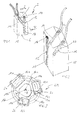
- Fig. 1 shows in isometric view a carbon brush 2 with a carbon fitting 13, which has two recesses 20 in its contact surface 6 opposite terminal end, in which connection conductor can be contacted via tamping contacts 11 of compressed conductive contact powder with a carbon fiber assembly 10, in a further recess 12th is received, which extends in the wear direction of the carbon fitting 13.
- the recess 12 extends through the carbon brush 2 in its longitudinal direction perpendicular to the connection surface 6.
- the fixed in the recess 12 carbon fiber assembly 10 is formed in the present case as a strand-like braid, with individual carbon fibers for stiffening in the CVD or CVI method with pyrolytically deposited Carbon coated.
- the carbon fiber arrangement 10 is fixed to the carbon brush 2 by means of a two-component epoxy adhesive depot 14 at the contact end of the carbon brush 2 opposite the contact surface 6.
- the recess 12 is designed such that the carbon fiber assembly 10 completely fills it, that is quasi nestled nestled in this.
- Fig. 3 is a ground contact shown, as it comes in rail vehicles used.
- the ground contact 22 after Fig. 3 is suitable to transmit electrical currents between a stationary vehicle part of a rail vehicle and a rotating Fahrndil, so about a hub.
- three carbon brushes 2a, 2b, 2c are arranged at uniform intervals in a brush holder 4, which are pressurized perpendicular to the contact surface and each have a carbon fiber arrangement 10a, 10b, 10c.
- the carbon fiber arrangements 10a, 10b, 10c are each arranged in a recess 12a, 12b, 12c penetrating through the carbon brushes 2a, 2b, 2c and fixed to the respective carbon brush 2a, 2b, 2c by means of a two-component epoxy adhesive depot 14
- the carbon fiber arrangements 10a, 10b, 10c of the carbon brushes 2a, 2b, 2c have different distances 16a, 16b, 16c to the axis of rotation 8.
- About the axis of rotation 8 rotates the not shown wheel axle of the rail vehicle and thus also a non-illustrated mating contact surface of the wheel hub, such that the contact surface 6 rests against the mating contact surface.
Landscapes
- Motor Or Generator Current Collectors (AREA)
Abstract
Description
- Die Erfindung betrifft eine Kohlebürste zur Ausbildung eines elektrischen Kontakts zwischen einem stromführenden Stator und einem stromführenden Rotor, derart, dass eine an einem als Kohlenstoffformstück ausgebildeten Bürstenkörper ausgebildete Kontaktfläche der Kohlebürste gegen eine Gegenkontaktfläche des Stators oder Rotors anliegt, wobei der Bürstenkörper eine sich vorzugsweise geradlinig in Abnutzungsrichtung des Bürstenkörpers erstreckende Sekundärleiteinrichtung aufweist, die mit einem Kontaktende in der Kontaktfläche des Bürstenkörpers angeordnet ist.
- Derartige Kohlebürsten werden beispielsweise bei Elektromotoren oder Erdungskontakten von Fahrzeugen, insbesondere von Schienenfahrzeugen, eingesetzt. Die Kohlebürste stellt einen Kontakt zur Übertragung von elektrischen Strömen zwischen einem feststehenden Element und einem rotierenden Element her, wobei die Kohlebürste an einem Bürstenhalter angeordnet, und eine Kontaktfläche der Kohlebürste mit einer Kontaktkraft an einer Gegenkontaktfläche anliegt, und die Kontaktfläche oder die Gegenkontaktfläche um eine Rotationsachse rotiert.
- Durch das Herstellen dieses Kontaktes zwischen dem feststehenden und dem rotationsfähigen Element ist es möglich, einen Stromkreis zu schließen. Bei Fahrzeugen, insbesondere Schienenfahrzeugen, erfüllt der Stromkreis insbesondere eine Erdungsfunktion.
- Der Kontakt, welcher sich zwischen der Kontaktfläche der Kohlebürste und der Gegenkontaktfläche einstellt, ist jedoch Einflüssen ausgesetzt, welche die Übertragung eines Stroms zumindest erschweren. Insbesondere besteht bei den bekannten Kohlebürsten das Problem, dass durch den betriebsbedingten Eintrag von Ölen und Fetten die Kontaktfläche bzw. die Gegenkontaktfläche benetzt wird. Aufgrund der Oberflächenbenetzung bildet sich bei hochfrequenten Strömen ein nachteiliger Skin-Effekt, wonach der Stromfluss durch die Kohlebürste nicht gleichmäßig über den ganzen Querschnitt erfolgt, sondern der Stromfluss magnetfeldbedingt vorwiegend an den Außenrändern der Kohlebürste erfolgt. Der Skin-Effekt führt folglich dazu, dass sich der nutzbare Kohlebürstenquerschnitt für den Elektronenfluss stark verringert.
- Der Erfindung liegt daher die Aufgabe zugrunde, eine Kohlebürste vorzuschlagen, welche der Ausbildung des Skin-Effekts entgegenwirkt.
- Diese Aufgabe ist erfindungsgemäß durch eine Kohlebürste mit den Merkmalen des Anspruchs 1 gelöst.
- Erfindungsgemäß weist die Sekundärleiteinrichtung zumindest eine Kohlenstofffaseranordnung auf mit Kohlefasern, deren Faserenden in der Kontaktfläche angeordnet sind, so dass die Kohlenstofffasern nicht nur eine besonders effektive Stromführung ermöglichen, sonder darüber hinaus die Faserenden einen benetzenden Film aufreißen und einen unmittelbaren Kontakt zur Gegenkontaktfläche ermöglichen. Die einzelnen Kohlenstofffasern erstrecken sich vorzugsweise über die gesamte Länge der Kohlenstofffaseranordnung, sind also vorzugsweise durch Filamente übereinstimmender Länge gebildet, die sich über die Gesamtlänge der Sekundärleiteinrichtung erstrecken.
- Gemäß einer bevorzugten Ausführungsform ist die Kohlenstofffaseranordnung innerhalb des Bürstenkörpers in einer Ausnehmung eingebettet aufgenommen. Die Integration der Kohlenstofffaseranordnung in die Kohlebürste führt dazu, dass der Formkörper zur Abstützung bzw. zur Versteifung der Kohlenstofffasern genutzt werden kann.
- Vorzugsweise sind die Kohlenstofffasern der Kohlenstofffaseranordnung in einer Stützmatrix angeordnet sind, die durch eine äußere Umhüllung der Kohlenstofffaseranordnung oder auch durch eine versteifte Ausbildung der einzelnen Kohlenstofffasern gebildet sein kann.
- Insbesondere können die Kohlenstofffasern der Kohlenstofffaseranordnung zur Versteifung ein litzen- oder drahtförmiges Fasergeflecht ausbilden.
- Vorzugsweise ist die Kohlenstofffaseranordnung mit einem vorzugsweise als Anschlusslitze ausgebildeten äußeren Anschlussleiter der Kohlebürste kontaktiert, so dass unabhängig vom Kohlenstoffformstück eine direkte elektrische Verbindung zwischen der Kohlenstofffaseranordnung und dem Anschlussleiter besteht.
- Wenn die Kontaktierung der Kohlenstofffaseranordnung über einen Stampfkontakt erfolgt, ist ein besonders geringer Kontaktwiderstand ausgebildet.
- Wenn der Stampfkontakt in einer schräg zur Kohlenstofffaseranordnung ausgerichteten und in die Ausnehmung der Kohlenstofffaseranordnung einmündenden Ausnehmung ausgebildet ist, kann als Anschlussfläche eine von der axialen Endfläche des Kohlenstoffformstück abweichende, insbesondere seitlich zur Endfläche angeordnete Fläche als äußere Anschlussfläche gewählt werden.
- Vorzugsweise weist die Sekundärleiteinrichtung zwei Kohlenstofffaseranordnungen aufweist, wobei zumindest eine über einen Stampfkontakt mit einem Anschlussleiter der Kohlebürste kontaktiert ist.
- Wenn die Sekundärleiteinrichtung zwei Kohlenstofffaseranordnungen aufweist, die jeweils über einen Stampfkontakt mit einem Anschlussleiter der Kohlebürste kontaktiert sind, kann eine funktionale Trennung der Kohlenstofffaseranordnungen erfolgen; beispielsweise kann eine Kohlenstofffaseranordnung als Verschleißkontakt genutzt werden, der eine Stromabschaltung bei Erreichen einer Verschleißgrenze bewirkt.
- Der erfindungsgemäße Erdungskontakt nach Anspruch 10 zur Übertragung von elektrischen Strömen zwischen einem feststehenden, einen Stator ausbildenden Fahrzeugteil und einem relativ zu dem feststehen Fahrzeugteil bewegten, einen Rotor ausbildenden Fahrzeugteil, weist eine zumindest eine Kohlebürste nach einem der vorhergehenden Ansprüche umfassende Bürstenanordnung auf.
- Gemäß einer bevorzugten Ausführungsform weist die Bürstenanordnung zumindest zwei konzentrisch zu einer Rotationsachse der Bürstenanordnung auf einem Bürstenkreis angeordnete Kohlebürsten auf, deren Kohlefaseranordnungen mit ihren Kontaktenden an unterschiedlichen Kontaktstellen in der Kontaktfläche der Bürstenkörper angeordnet sind, derart, dass die Kontaktstellen unterschiedliche Abstände zur Rotationsachse der Bürstenanordnung aufweisen.
- Gemäß einer alternativen Ausführungsform nach Anspruch 12 weist die Bürstenanordnung zumindest zwei mit unterschiedlichen Abständen zu einer Rotationsachse der Bürstenanordnung auf einem Bürstenkreis angeordnete Kohlebürsten auf, deren Kohlefaseranordnungen mit ihren Kontaktenden an übereinstimmenden Kontaktstellen in der Kontaktfläche der Bürstenkörper angeordnet sind, derart, dass die Kontaktstellen unterschiedliche Abstände zur Rotationsachse der Bürstenanordnung aufweisen.
- Durch die vorstehenden alternativen Ausführungsformen ist es möglich, einen benetzenden Fett- oder Ölfilm an mehreren Stellen und somit großflächig aufzureißen. Durch die Definition mehrerer Kreisbahnen wird zudem die Gegenkontaktfläche gleichmäßig belastet.
- Ein Ausführungsbeispiel einer Kohlebürste nach der Erfindung ist in der Zeichnung schematisch vereinfacht dargestellt und wird in der nachfolgenden Beschreibung näher erläutert. Es zeigt:
- Fig. 1
- eine perspektivische Ansicht einer Ausführungsform einer Kohlebürste;
- Fig. 2
- einen Schnitt durch die Kohlebürste nach
Fig. 1 entlang der Linie II-II; - Fig. 3
- eine Draufsicht auf einen Erdungskontakt mit einer Mehrzahl von Kohlebürsten.
-
Fig. 1 zeigt in isometrischer Darstellung eine Kohlebürste 2 mit einem Kohlenstoffformstück 13, das in seinem einer Kontaktfläche 6 gegenüber liegenden Anschlussende zwei Ausnehmungen 20 aufweist, in welchen Anschlussleiter über Stampfkontakte 11 aus komprimiertem leitfähigem Kontaktpulver mit einer Kohlenstofffaseranordnung 10 kontaktiert werden können, die in einer weitere Ausnehmung 12 aufgenommen ist, die sich in Abnutzungsrichtung des Kohlenstoffformstücks 13 erstreckt. - Die Ausnehmung 12 durchgreift die Kohlebürste 2 in ihrer Längsrichtung senkrecht zur Anschlussfläche 6. Die in der Ausnehmung 12 fixierte Kohlenstofffaseranordnung 10 ist im vorliegenden Fall als ein litzenförmiges Geflecht ausgebildet, mit einzelnen Kohlenstofffasern, die zur Versteifung im CVD- oder CVI-Verfahren mit pyrolytisch abgeschiedenem Kohlenstoff beschichtet sind.
- An dem der Kontaktfläche 6 gegenüberliegenden Kontaktende der Kohlebürste 2 ist die Kohlenstofffaseranordnung 10 mittels eines Zweikomponenten-Epoxidkleberdepots 14 an der Kohlebürste 2 fixiert. Die Ausnehmung 12 ist derart ausgeführt, dass die Kohlenstofffaseranordnung 10 diese gänzlich ausfüllt, also quasi angeschmiegt in dieser eingebettet ist.
- In
Fig. 3 ist ein Erdungskontakt abgebildet, wie er bei Schienenfahrzeugen zum Einsatz kommt. Der Erdungskontakt 22 nachFig. 3 ist geeignet, elektrische Ströme zwischen einem feststehenden Fahrzeugteil eines Schienenfahrzeugs und einem rotierenden Fahrzeigteil, also etwa einer Radnabe zu übertragen. Hierzu sind in gleichmäßigen Abständen in einem Bürstenhalter 4 drei Kohlebürsten 2a, 2b, 2c angeordnet, welche senkrecht zur Kontaktfläche druckbeaufschlagt sind und je eine Kohlenstofffaseranordnung 10a, 10b, 10c aufweisen. Die Kohlenstofffaseranordnungen 10a, 10b, 10c sind jeweils in einer die Kohlebürsten 2a, 2b, 2c durchgreifenden Ausnehmung 12a, 12b, 12c angeordnet und mittels eines Zweikomponenten-Epoxidklebstoffdepots 14 an der jeweiligen Kohlebürste 2a, 2b, 2c fixiert - Die Kohlenstofffaseranordnungen 10a, 10b, 10c der Kohlebürsten 2a, 2b, 2c weisen unterschiedliche Abstände 16a, 16b, 16c zur Rotationsachse 8 auf. Um die Rotationsachse 8 rotiert die nicht weiter dargestellte Radachse des Schienenfahrzeugs und somit auch eine nicht näher dargestellte Gegenkontaktfläche der Radnabe, derart, dass die Kontaktfläche 6 an der Gegenkontaktfläche anliegt. Durch die unterschiedlichen Abstände 16a, 16b, 16c zur Rotationsachse 8 definiert jede der drei Kohlenstofffaseranordnungen 10a, 10b, 10c eine separate Kreisbahn 18a, 18b, 18c auf der Gegenkontaktfläche.
Claims (12)
- Kohlebürste (2) zur Ausbildung eines elektrischen Kontakts zwischen einem stromführenden Stator und einem stromführenden Rotor, derart, dass eine an einem als Kohlenstoffformstück (13) ausgebildeten Bürstenkörper ausgebildete Kontaktfläche (6) der Kohlebürste gegen eine Gegenkontaktfläche des Stators oder Rotors anliegt, wobei der Bürstenkörper eine sich vorzugsweise geradlinig in Abnutzungsrichtung des Bürstenkörpers erstreckende Sekundärleiteinrichtung aufweist, die mit einem Kontaktende in der Kontaktfläche des Bürstenkörpers angeordnet ist,
dadurch gekennzeichnet,
dass die Sekundärleiteinrichtung zumindest eine Kohlefaseranordnung (10) aufweist mit Kohlefasern, deren Faserenden in der Kontaktfläche angeordnet sind. - Kohlebürste nach Anspruch 1,
dadurch gekennzeichnet,
dass die Kohlenstofffaseranordnung (10) innerhalb des Bürstenkörpers in einer Ausnehmung (12) eingebettet aufgenommen ist. - Kohlebürste nach einem der Ansprüche 1 oder 2,
dadurch gekennzeichnet,
dass die Kohlenstofffasern der Kohlenstofffaseranordnung (10) in einer Stützmatrix angeordnet sind. - Kohlebürste nach einem der Ansprüche 1 bis 3,
dadurch gekennzeichnet,
dass die Kohlenstofffasern der Kohlenstofffaseranordnung (10) ein Fasergeflecht ausbilden. - Kohlebürste nach einem der vorangehenden Ansprüche,
dadurch gekennzeichnet,
dass die Kohlenstofffaseranordnung (10) mit einem Anschlussleiter der Kohlebürste kontaktiert ist. - Kohlebürste nach Anspruch 5,
dadurch gekennzeichnet,
dass die Kontaktierung der Kohlenstofffaseranordnung (10) über einen Stampfkontakt (11) erfolgt. - Kohlebürste nach Anspruch 6,
dadurch gekennzeichnet,
dass der Stampfkontakt (11) in einer schräg zur Kohlenstofffaseranordnung ausgerichteten und in die Ausnehmung (12) der Kohlenstofffaseranordnung (10) einmündenden Ausnehmung (20) ausgebildet ist. - Kohlebürste nach Anspruch 6 oder 7,
dadurch gekennzeichnet,
dass die Sekundärleiteinrichtung zwei Kohlenstofffaseranordnungen (10) aufweist, von denen zumindest eine über einen Stampfkontakt (11) mit einem Anschlussleiter der Kohlebürste kontaktiert sind. - Kohlebürste nach Anspruch 8,
dadurch gekennzeichnet,
dass beide Kohlenstofffaseranordnungen (10) über einen Stampfkontakt (11) mit einem Anschlussleiter der Kohlebürste kontaktiert sind. - Erdungskontakt, insbesondere Erdungskontakt für ein Schienenfahrzeug, zur Übertragung von elektrischen Strömen zwischen einem feststehenden, einen Stator ausbildenden Fahrzeugteil und einem relativ zu dem feststehen Fahrzeugteil bewegten, einen Rotor ausbildenden Fahrzeugteil, mit einer zumindest eine Kohlebürste (2) nach einem der vorhergehenden Ansprüche umfassenden Bürstenanordnung.
- Erdungskontakt nach Anspruch 10,
dadurch gekennzeichnet,
dass die Bürstenanordnung zumindest zwei konzentrisch zu einer Rotationsachse (8) der Bürstenanordnung auf einem Bürstenkreis angeordnete Kohlebürsten (2a, 2b, 2c) aufweist, deren Kohlefaseranordnungen (10) mit ihren Kontaktenden an unterschiedlichen Kontaktstellen in der Kontaktfläche (6) der Bürstenkörper angeordnet sind, derart, dass die Kontaktstellen (10a, 10b, 10c) unterschiedliche Abstände (16a, 16b, 16c) zur Rotationsachse der Bürstenanordnung aufweisen. - Erdungskontakt nach Anspruch 10,
dadurch gekennzeichnet,
dass die Bürstenanordnung zumindest zwei mit unterschiedlichen Abständen zu einer Rotationsachse (8) der Bürstenanordnung auf einem Bürstenkreis angeordnete Kohlebürsten (2a, 2b, 2c) aufweist, deren Kohlefaseranordnungen (10) mit ihren Kontaktenden an übereinstimmenden Kontaktstellen in der Kontaktfläche (6) der Bürstenkörper angeordnet sind, derart, dass die Kontaktstellen (10a, 10b, 10c) unterschiedliche Abstände (16a, 16b, 16c) zur Rotationsachse der Bürstenanordnung aufweisen.
Priority Applications (1)
| Application Number | Priority Date | Filing Date | Title |
|---|---|---|---|
| PL14197186T PL2884602T3 (pl) | 2013-12-10 | 2014-12-10 | Szczotka węglowa |
Applications Claiming Priority (1)
| Application Number | Priority Date | Filing Date | Title |
|---|---|---|---|
| DE102013020386.4A DE102013020386A1 (de) | 2013-12-10 | 2013-12-10 | Kohlebürste |
Publications (2)
| Publication Number | Publication Date |
|---|---|
| EP2884602A1 true EP2884602A1 (de) | 2015-06-17 |
| EP2884602B1 EP2884602B1 (de) | 2017-02-08 |
Family
ID=52016486
Family Applications (1)
| Application Number | Title | Priority Date | Filing Date |
|---|---|---|---|
| EP14197186.1A Not-in-force EP2884602B1 (de) | 2013-12-10 | 2014-12-10 | Kohlebürste |
Country Status (3)
| Country | Link |
|---|---|
| EP (1) | EP2884602B1 (de) |
| DE (1) | DE102013020386A1 (de) |
| PL (1) | PL2884602T3 (de) |
Cited By (2)
| Publication number | Priority date | Publication date | Assignee | Title |
|---|---|---|---|---|
| CN110311275A (zh) * | 2018-03-20 | 2019-10-08 | 斯凯孚公司 | 纤维接地刷、包括纤维接地刷的组件和安装该组件的方法 |
| CN111137181A (zh) * | 2020-01-02 | 2020-05-12 | 中车株洲电力机车有限公司 | 一种接地装置、转向架和轨道交通机车车辆 |
Families Citing this family (1)
| Publication number | Priority date | Publication date | Assignee | Title |
|---|---|---|---|---|
| CN118352857B (zh) * | 2024-05-20 | 2025-09-12 | 中车青岛四方车辆研究所有限公司 | 一种轨道车辆轴端接地装置、转向架及轨道车辆 |
Citations (4)
| Publication number | Priority date | Publication date | Assignee | Title |
|---|---|---|---|---|
| US2739255A (en) * | 1954-11-16 | 1956-03-20 | Stackpole Carbon Co | High altitude brushes |
| FR1470029A (fr) * | 1966-02-24 | 1967-02-17 | Balai composite pour anneau collecteur d'appareils électriques | |
| US3509400A (en) * | 1966-05-17 | 1970-04-28 | Sigri Elektrographit Gmbh | Commutator carbon brush and method of its manufacture |
| US3886386A (en) * | 1973-08-01 | 1975-05-27 | Gen Electric | Carbon fiber current collection brush |
Family Cites Families (7)
| Publication number | Priority date | Publication date | Assignee | Title |
|---|---|---|---|---|
| DE1638186A1 (de) * | 1967-03-13 | 1970-01-29 | Carbone Ag | Gepresste Kohlebuerste fuer Kleinelektromotoren und Kleindynamos |
| GB1369835A (en) * | 1971-12-20 | 1974-10-09 | Morganite Carbon Ltd | Brushes for electric machines |
| DE3239003A1 (de) * | 1982-10-21 | 1984-04-26 | Hübner Elektromaschinen AG, 1000 Berlin | Kohlebuerste fuer elektrische maschine |
| DE4127336A1 (de) * | 1991-08-19 | 1993-02-25 | Schunk Metall & Kunststoff | Haltevorrichtung fuer an schienenfahrzeugen als rueckstrom- und/oder erdungskontakt eingesetzte buersten und verfahren zur herstellung einer solchen haltevorrichtung |
| DE19913599A1 (de) * | 1999-03-25 | 2000-09-28 | Schunk Kohlenstofftechnik Gmbh | Mehrschicht-Kohlebürste |
| FR2889628B1 (fr) * | 2005-08-08 | 2007-11-09 | Valeo Systemes Dessuyage | Balai et machine electrique tournante equipee d'un tel balai |
| JP2007097254A (ja) * | 2005-09-27 | 2007-04-12 | Toshiba Ceramics Co Ltd | 電気機械用ブラシ |
-
2013
- 2013-12-10 DE DE102013020386.4A patent/DE102013020386A1/de not_active Withdrawn
-
2014
- 2014-12-10 PL PL14197186T patent/PL2884602T3/pl unknown
- 2014-12-10 EP EP14197186.1A patent/EP2884602B1/de not_active Not-in-force
Patent Citations (4)
| Publication number | Priority date | Publication date | Assignee | Title |
|---|---|---|---|---|
| US2739255A (en) * | 1954-11-16 | 1956-03-20 | Stackpole Carbon Co | High altitude brushes |
| FR1470029A (fr) * | 1966-02-24 | 1967-02-17 | Balai composite pour anneau collecteur d'appareils électriques | |
| US3509400A (en) * | 1966-05-17 | 1970-04-28 | Sigri Elektrographit Gmbh | Commutator carbon brush and method of its manufacture |
| US3886386A (en) * | 1973-08-01 | 1975-05-27 | Gen Electric | Carbon fiber current collection brush |
Cited By (3)
| Publication number | Priority date | Publication date | Assignee | Title |
|---|---|---|---|---|
| CN110311275A (zh) * | 2018-03-20 | 2019-10-08 | 斯凯孚公司 | 纤维接地刷、包括纤维接地刷的组件和安装该组件的方法 |
| US11309775B2 (en) | 2018-03-20 | 2022-04-19 | Aktiebolaget Skf | Fiber grounding brush assembly |
| CN111137181A (zh) * | 2020-01-02 | 2020-05-12 | 中车株洲电力机车有限公司 | 一种接地装置、转向架和轨道交通机车车辆 |
Also Published As
| Publication number | Publication date |
|---|---|
| PL2884602T3 (pl) | 2017-07-31 |
| DE102013020386A1 (de) | 2015-06-11 |
| EP2884602B1 (de) | 2017-02-08 |
Similar Documents
| Publication | Publication Date | Title |
|---|---|---|
| EP3276755A1 (de) | Steckverbindungsteil für eine geschirmte steckverbindungseinheit | |
| DE102017210425A1 (de) | Modulverbinder | |
| EP2797175B1 (de) | Stecker für ein mehrere Adern aufweisendes Daten- und/oder Telekommunikations-Kabel | |
| WO2010043290A1 (de) | Schleifringeinheit | |
| WO2009056098A1 (de) | Dichtelement für ein lager, insbesondere für ein wälzlager | |
| WO2012146498A1 (de) | Bürstenanordnung in einer kommutierungseinrichtung | |
| EP2884602B1 (de) | Kohlebürste | |
| EP3262726A1 (de) | Hv-kabelsatz | |
| DE102014110962B3 (de) | Entstörwiderstand für ein Zündsystem und Zündkerzenstecker mit einem solchen Entstörwiderstand | |
| DE102009040106A1 (de) | Schleifringvorrichtung | |
| EP0035700B1 (de) | Digitale elektrische Winkelmesseinrichtung | |
| EP3345198B1 (de) | Hochspannungsvorrichtung und verfahren zu deren herstellung | |
| DE102018200195B4 (de) | Antrieb mit einem kommutatormotor | |
| DE102010013500A1 (de) | Steckervorrichtung und Verfahren zur Herstellung der Steckervorrichtung | |
| DE102005034584B4 (de) | Kohlebürstenanordnung | |
| EP2584676B1 (de) | Ableitungseinrichtung | |
| DE102021206252A1 (de) | Gehäuseteil für eine elektrische Komponente sowie elektrische Komponente mit Gehäuseteil | |
| DE102017209868B4 (de) | Kontaktierungselement für Twinaxialkabel | |
| EP1705957B1 (de) | Elektrischer Heizleiter | |
| WO2014012822A1 (de) | Elektrische kontakteinrichtung zur kontaktierung eines elektrischen leiters | |
| WO2018091332A1 (de) | Strombalken für eine anschlussklemme | |
| DE102019126819B3 (de) | Geschirmter Rundsteckverbinder und ein Verfahren zu dessen Herstellung | |
| DE102023114105A1 (de) | Kontakteinrichtung für einen steckverbinder und steckverbinder mit zumindest einer kontakteinrichtung | |
| DE8005990U1 (de) | Digitale elektrische Winkelmeßeinrichtung | |
| DE102024120030A1 (de) | Leiteranschlussklemme |
Legal Events
| Date | Code | Title | Description |
|---|---|---|---|
| PUAI | Public reference made under article 153(3) epc to a published international application that has entered the european phase |
Free format text: ORIGINAL CODE: 0009012 |
|
| 17P | Request for examination filed |
Effective date: 20141210 |
|
| AK | Designated contracting states |
Kind code of ref document: A1 Designated state(s): AL AT BE BG CH CY CZ DE DK EE ES FI FR GB GR HR HU IE IS IT LI LT LU LV MC MK MT NL NO PL PT RO RS SE SI SK SM TR |
|
| AX | Request for extension of the european patent |
Extension state: BA ME |
|
| R17P | Request for examination filed (corrected) |
Effective date: 20151217 |
|
| RBV | Designated contracting states (corrected) |
Designated state(s): AL AT BE BG CH CY CZ DE DK EE ES FI FR GB GR HR HU IE IS IT LI LT LU LV MC MK MT NL NO PL PT RO RS SE SI SK SM TR |
|
| GRAP | Despatch of communication of intention to grant a patent |
Free format text: ORIGINAL CODE: EPIDOSNIGR1 |
|
| INTG | Intention to grant announced |
Effective date: 20160928 |
|
| STAA | Information on the status of an ep patent application or granted ep patent |
Free format text: STATUS: GRANT OF PATENT IS INTENDED |
|
| GRAS | Grant fee paid |
Free format text: ORIGINAL CODE: EPIDOSNIGR3 |
|
| GRAA | (expected) grant |
Free format text: ORIGINAL CODE: 0009210 |
|
| STAA | Information on the status of an ep patent application or granted ep patent |
Free format text: STATUS: THE PATENT HAS BEEN GRANTED |
|
| AK | Designated contracting states |
Kind code of ref document: B1 Designated state(s): AL AT BE BG CH CY CZ DE DK EE ES FI FR GB GR HR HU IE IS IT LI LT LU LV MC MK MT NL NO PL PT RO RS SE SI SK SM TR |
|
| REG | Reference to a national code |
Ref country code: GB Ref legal event code: FG4D Free format text: NOT ENGLISH |
|
| REG | Reference to a national code |
Ref country code: CH Ref legal event code: EP Ref country code: AT Ref legal event code: REF Ref document number: 867230 Country of ref document: AT Kind code of ref document: T Effective date: 20170215 |
|
| REG | Reference to a national code |
Ref country code: IE Ref legal event code: FG4D Free format text: LANGUAGE OF EP DOCUMENT: GERMAN |
|
| REG | Reference to a national code |
Ref country code: DE Ref legal event code: R096 Ref document number: 502014002661 Country of ref document: DE |
|
| REG | Reference to a national code |
Ref country code: CH Ref legal event code: NV Representative=s name: FREI PATENTANWALTSBUERO AG, CH |
|
| REG | Reference to a national code |
Ref country code: LT Ref legal event code: MG4D |
|
| REG | Reference to a national code |
Ref country code: NL Ref legal event code: MP Effective date: 20170208 |
|
| PG25 | Lapsed in a contracting state [announced via postgrant information from national office to epo] |
Ref country code: HR Free format text: LAPSE BECAUSE OF FAILURE TO SUBMIT A TRANSLATION OF THE DESCRIPTION OR TO PAY THE FEE WITHIN THE PRESCRIBED TIME-LIMIT Effective date: 20170208 Ref country code: NO Free format text: LAPSE BECAUSE OF FAILURE TO SUBMIT A TRANSLATION OF THE DESCRIPTION OR TO PAY THE FEE WITHIN THE PRESCRIBED TIME-LIMIT Effective date: 20170508 Ref country code: LT Free format text: LAPSE BECAUSE OF FAILURE TO SUBMIT A TRANSLATION OF THE DESCRIPTION OR TO PAY THE FEE WITHIN THE PRESCRIBED TIME-LIMIT Effective date: 20170208 Ref country code: FI Free format text: LAPSE BECAUSE OF FAILURE TO SUBMIT A TRANSLATION OF THE DESCRIPTION OR TO PAY THE FEE WITHIN THE PRESCRIBED TIME-LIMIT Effective date: 20170208 Ref country code: GR Free format text: LAPSE BECAUSE OF FAILURE TO SUBMIT A TRANSLATION OF THE DESCRIPTION OR TO PAY THE FEE WITHIN THE PRESCRIBED TIME-LIMIT Effective date: 20170509 |
|
| PG25 | Lapsed in a contracting state [announced via postgrant information from national office to epo] |
Ref country code: LV Free format text: LAPSE BECAUSE OF FAILURE TO SUBMIT A TRANSLATION OF THE DESCRIPTION OR TO PAY THE FEE WITHIN THE PRESCRIBED TIME-LIMIT Effective date: 20170208 Ref country code: ES Free format text: LAPSE BECAUSE OF FAILURE TO SUBMIT A TRANSLATION OF THE DESCRIPTION OR TO PAY THE FEE WITHIN THE PRESCRIBED TIME-LIMIT Effective date: 20170208 Ref country code: RS Free format text: LAPSE BECAUSE OF FAILURE TO SUBMIT A TRANSLATION OF THE DESCRIPTION OR TO PAY THE FEE WITHIN THE PRESCRIBED TIME-LIMIT Effective date: 20170208 Ref country code: NL Free format text: LAPSE BECAUSE OF FAILURE TO SUBMIT A TRANSLATION OF THE DESCRIPTION OR TO PAY THE FEE WITHIN THE PRESCRIBED TIME-LIMIT Effective date: 20170208 Ref country code: BG Free format text: LAPSE BECAUSE OF FAILURE TO SUBMIT A TRANSLATION OF THE DESCRIPTION OR TO PAY THE FEE WITHIN THE PRESCRIBED TIME-LIMIT Effective date: 20170508 Ref country code: SE Free format text: LAPSE BECAUSE OF FAILURE TO SUBMIT A TRANSLATION OF THE DESCRIPTION OR TO PAY THE FEE WITHIN THE PRESCRIBED TIME-LIMIT Effective date: 20170208 Ref country code: PT Free format text: LAPSE BECAUSE OF FAILURE TO SUBMIT A TRANSLATION OF THE DESCRIPTION OR TO PAY THE FEE WITHIN THE PRESCRIBED TIME-LIMIT Effective date: 20170608 |
|
| PG25 | Lapsed in a contracting state [announced via postgrant information from national office to epo] |
Ref country code: RO Free format text: LAPSE BECAUSE OF FAILURE TO SUBMIT A TRANSLATION OF THE DESCRIPTION OR TO PAY THE FEE WITHIN THE PRESCRIBED TIME-LIMIT Effective date: 20170208 Ref country code: EE Free format text: LAPSE BECAUSE OF FAILURE TO SUBMIT A TRANSLATION OF THE DESCRIPTION OR TO PAY THE FEE WITHIN THE PRESCRIBED TIME-LIMIT Effective date: 20170208 Ref country code: SK Free format text: LAPSE BECAUSE OF FAILURE TO SUBMIT A TRANSLATION OF THE DESCRIPTION OR TO PAY THE FEE WITHIN THE PRESCRIBED TIME-LIMIT Effective date: 20170208 Ref country code: CZ Free format text: LAPSE BECAUSE OF FAILURE TO SUBMIT A TRANSLATION OF THE DESCRIPTION OR TO PAY THE FEE WITHIN THE PRESCRIBED TIME-LIMIT Effective date: 20170208 |
|
| REG | Reference to a national code |
Ref country code: DE Ref legal event code: R097 Ref document number: 502014002661 Country of ref document: DE |
|
| PG25 | Lapsed in a contracting state [announced via postgrant information from national office to epo] |
Ref country code: SM Free format text: LAPSE BECAUSE OF FAILURE TO SUBMIT A TRANSLATION OF THE DESCRIPTION OR TO PAY THE FEE WITHIN THE PRESCRIBED TIME-LIMIT Effective date: 20170208 Ref country code: DK Free format text: LAPSE BECAUSE OF FAILURE TO SUBMIT A TRANSLATION OF THE DESCRIPTION OR TO PAY THE FEE WITHIN THE PRESCRIBED TIME-LIMIT Effective date: 20170208 |
|
| PLBE | No opposition filed within time limit |
Free format text: ORIGINAL CODE: 0009261 |
|
| STAA | Information on the status of an ep patent application or granted ep patent |
Free format text: STATUS: NO OPPOSITION FILED WITHIN TIME LIMIT |
|
| REG | Reference to a national code |
Ref country code: FR Ref legal event code: PLFP Year of fee payment: 4 |
|
| 26N | No opposition filed |
Effective date: 20171109 |
|
| PG25 | Lapsed in a contracting state [announced via postgrant information from national office to epo] |
Ref country code: SI Free format text: LAPSE BECAUSE OF FAILURE TO SUBMIT A TRANSLATION OF THE DESCRIPTION OR TO PAY THE FEE WITHIN THE PRESCRIBED TIME-LIMIT Effective date: 20170208 |
|
| REG | Reference to a national code |
Ref country code: IE Ref legal event code: MM4A |
|
| PG25 | Lapsed in a contracting state [announced via postgrant information from national office to epo] |
Ref country code: MT Free format text: LAPSE BECAUSE OF FAILURE TO SUBMIT A TRANSLATION OF THE DESCRIPTION OR TO PAY THE FEE WITHIN THE PRESCRIBED TIME-LIMIT Effective date: 20170208 Ref country code: LU Free format text: LAPSE BECAUSE OF NON-PAYMENT OF DUE FEES Effective date: 20171210 |
|
| PG25 | Lapsed in a contracting state [announced via postgrant information from national office to epo] |
Ref country code: IE Free format text: LAPSE BECAUSE OF NON-PAYMENT OF DUE FEES Effective date: 20171210 |
|
| REG | Reference to a national code |
Ref country code: CH Ref legal event code: PCAR Free format text: NEW ADDRESS: POSTFACH, 8032 ZUERICH (CH) |
|
| PG25 | Lapsed in a contracting state [announced via postgrant information from national office to epo] |
Ref country code: MC Free format text: LAPSE BECAUSE OF FAILURE TO SUBMIT A TRANSLATION OF THE DESCRIPTION OR TO PAY THE FEE WITHIN THE PRESCRIBED TIME-LIMIT Effective date: 20170208 Ref country code: HU Free format text: LAPSE BECAUSE OF FAILURE TO SUBMIT A TRANSLATION OF THE DESCRIPTION OR TO PAY THE FEE WITHIN THE PRESCRIBED TIME-LIMIT; INVALID AB INITIO Effective date: 20141210 |
|
| GBPC | Gb: european patent ceased through non-payment of renewal fee |
Effective date: 20181210 |
|
| PG25 | Lapsed in a contracting state [announced via postgrant information from national office to epo] |
Ref country code: CY Free format text: LAPSE BECAUSE OF FAILURE TO SUBMIT A TRANSLATION OF THE DESCRIPTION OR TO PAY THE FEE WITHIN THE PRESCRIBED TIME-LIMIT Effective date: 20170208 |
|
| PG25 | Lapsed in a contracting state [announced via postgrant information from national office to epo] |
Ref country code: MK Free format text: LAPSE BECAUSE OF FAILURE TO SUBMIT A TRANSLATION OF THE DESCRIPTION OR TO PAY THE FEE WITHIN THE PRESCRIBED TIME-LIMIT Effective date: 20170208 |
|
| PG25 | Lapsed in a contracting state [announced via postgrant information from national office to epo] |
Ref country code: GB Free format text: LAPSE BECAUSE OF NON-PAYMENT OF DUE FEES Effective date: 20181210 |
|
| PG25 | Lapsed in a contracting state [announced via postgrant information from national office to epo] |
Ref country code: TR Free format text: LAPSE BECAUSE OF FAILURE TO SUBMIT A TRANSLATION OF THE DESCRIPTION OR TO PAY THE FEE WITHIN THE PRESCRIBED TIME-LIMIT Effective date: 20170208 |
|
| PG25 | Lapsed in a contracting state [announced via postgrant information from national office to epo] |
Ref country code: AL Free format text: LAPSE BECAUSE OF FAILURE TO SUBMIT A TRANSLATION OF THE DESCRIPTION OR TO PAY THE FEE WITHIN THE PRESCRIBED TIME-LIMIT Effective date: 20170208 Ref country code: IS Free format text: LAPSE BECAUSE OF FAILURE TO SUBMIT A TRANSLATION OF THE DESCRIPTION OR TO PAY THE FEE WITHIN THE PRESCRIBED TIME-LIMIT Effective date: 20170608 |
|
| PGFP | Annual fee paid to national office [announced via postgrant information from national office to epo] |
Ref country code: AT Payment date: 20211221 Year of fee payment: 8 Ref country code: FR Payment date: 20211227 Year of fee payment: 8 |
|
| PGFP | Annual fee paid to national office [announced via postgrant information from national office to epo] |
Ref country code: IT Payment date: 20211220 Year of fee payment: 8 Ref country code: CH Payment date: 20211222 Year of fee payment: 8 Ref country code: BE Payment date: 20211227 Year of fee payment: 8 |
|
| PGFP | Annual fee paid to national office [announced via postgrant information from national office to epo] |
Ref country code: PL Payment date: 20211201 Year of fee payment: 8 |
|
| PGFP | Annual fee paid to national office [announced via postgrant information from national office to epo] |
Ref country code: DE Payment date: 20220225 Year of fee payment: 8 |
|
| REG | Reference to a national code |
Ref country code: DE Ref legal event code: R119 Ref document number: 502014002661 Country of ref document: DE |
|
| REG | Reference to a national code |
Ref country code: CH Ref legal event code: PL |
|
| REG | Reference to a national code |
Ref country code: AT Ref legal event code: MM01 Ref document number: 867230 Country of ref document: AT Kind code of ref document: T Effective date: 20221210 |
|
| REG | Reference to a national code |
Ref country code: BE Ref legal event code: MM Effective date: 20221231 |
|
| PG25 | Lapsed in a contracting state [announced via postgrant information from national office to epo] |
Ref country code: LI Free format text: LAPSE BECAUSE OF NON-PAYMENT OF DUE FEES Effective date: 20221231 Ref country code: DE Free format text: LAPSE BECAUSE OF NON-PAYMENT OF DUE FEES Effective date: 20230701 Ref country code: CH Free format text: LAPSE BECAUSE OF NON-PAYMENT OF DUE FEES Effective date: 20221231 Ref country code: AT Free format text: LAPSE BECAUSE OF NON-PAYMENT OF DUE FEES Effective date: 20221210 |
|
| PG25 | Lapsed in a contracting state [announced via postgrant information from national office to epo] |
Ref country code: FR Free format text: LAPSE BECAUSE OF NON-PAYMENT OF DUE FEES Effective date: 20221231 Ref country code: BE Free format text: LAPSE BECAUSE OF NON-PAYMENT OF DUE FEES Effective date: 20221231 |
|
| PG25 | Lapsed in a contracting state [announced via postgrant information from national office to epo] |
Ref country code: IT Free format text: LAPSE BECAUSE OF NON-PAYMENT OF DUE FEES Effective date: 20221210 |
|
| PG25 | Lapsed in a contracting state [announced via postgrant information from national office to epo] |
Ref country code: PL Free format text: LAPSE BECAUSE OF NON-PAYMENT OF DUE FEES Effective date: 20221210 |