EP2884607B1 - Enfouisseuse de câbles et procédé de fonctionnement d'une enfouisseuse de câbles - Google Patents
Enfouisseuse de câbles et procédé de fonctionnement d'une enfouisseuse de câbles Download PDFInfo
- Publication number
- EP2884607B1 EP2884607B1 EP14194261.5A EP14194261A EP2884607B1 EP 2884607 B1 EP2884607 B1 EP 2884607B1 EP 14194261 A EP14194261 A EP 14194261A EP 2884607 B1 EP2884607 B1 EP 2884607B1
- Authority
- EP
- European Patent Office
- Prior art keywords
- blade
- line guide
- control cylinder
- ground
- guide
- Prior art date
- Legal status (The legal status is an assumption and is not a legal conclusion. Google has not performed a legal analysis and makes no representation as to the accuracy of the status listed.)
- Active
Links
Images


Classifications
-
- H—ELECTRICITY
- H02—GENERATION; CONVERSION OR DISTRIBUTION OF ELECTRIC POWER
- H02G—INSTALLATION OF ELECTRIC CABLES OR LINES, OR OF COMBINED OPTICAL AND ELECTRIC CABLES OR LINES
- H02G1/00—Methods or apparatus specially adapted for installing, maintaining, repairing or dismantling electric cables or lines
- H02G1/06—Methods or apparatus specially adapted for installing, maintaining, repairing or dismantling electric cables or lines for laying cables, e.g. laying apparatus on vehicle
-
- E—FIXED CONSTRUCTIONS
- E02—HYDRAULIC ENGINEERING; FOUNDATIONS; SOIL SHIFTING
- E02F—DREDGING; SOIL-SHIFTING
- E02F5/00—Dredgers or soil-shifting machines for special purposes
- E02F5/02—Dredgers or soil-shifting machines for special purposes for digging trenches or ditches
- E02F5/10—Dredgers or soil-shifting machines for special purposes for digging trenches or ditches with arrangements for reinforcing trenches or ditches; with arrangements for making or assembling conduits or for laying conduits or cables
- E02F5/102—Dredgers or soil-shifting machines for special purposes for digging trenches or ditches with arrangements for reinforcing trenches or ditches; with arrangements for making or assembling conduits or for laying conduits or cables operatively associated with mole-ploughs, coulters
-
- E—FIXED CONSTRUCTIONS
- E02—HYDRAULIC ENGINEERING; FOUNDATIONS; SOIL SHIFTING
- E02F—DREDGING; SOIL-SHIFTING
- E02F5/00—Dredgers or soil-shifting machines for special purposes
- E02F5/02—Dredgers or soil-shifting machines for special purposes for digging trenches or ditches
- E02F5/14—Component parts for trench excavators, e.g. indicating devices travelling gear chassis, supports, skids
- E02F5/145—Component parts for trench excavators, e.g. indicating devices travelling gear chassis, supports, skids control and indicating devices
-
- F—MECHANICAL ENGINEERING; LIGHTING; HEATING; WEAPONS; BLASTING
- F16—ENGINEERING ELEMENTS AND UNITS; GENERAL MEASURES FOR PRODUCING AND MAINTAINING EFFECTIVE FUNCTIONING OF MACHINES OR INSTALLATIONS; THERMAL INSULATION IN GENERAL
- F16L—PIPES; JOINTS OR FITTINGS FOR PIPES; SUPPORTS FOR PIPES, CABLES OR PROTECTIVE TUBING; MEANS FOR THERMAL INSULATION IN GENERAL
- F16L1/00—Laying or reclaiming pipes; Repairing or joining pipes on or under water
- F16L1/024—Laying or reclaiming pipes on land, e.g. above the ground
- F16L1/028—Laying or reclaiming pipes on land, e.g. above the ground in the ground
- F16L1/032—Laying or reclaiming pipes on land, e.g. above the ground in the ground the pipes being continuous
-
- H—ELECTRICITY
- H02—GENERATION; CONVERSION OR DISTRIBUTION OF ELECTRIC POWER
- H02G—INSTALLATION OF ELECTRIC CABLES OR LINES, OR OF COMBINED OPTICAL AND ELECTRIC CABLES OR LINES
- H02G9/00—Installations of electric cables or lines in or on the ground or water
- H02G9/02—Installations of electric cables or lines in or on the ground or water laid directly in or on the ground, river-bed or sea-bottom; Coverings therefor, e.g. tile
Definitions
- the invention relates to a cable plow for introducing at least one line, in particular at least one pipe or cable, into the ground and a method for operating a cable plow.
- Such a cable plow comprises a suitable for engaging in the ground sword and a cable guide for inserting the line in the formed or formable by the sword gutter to form a gutter.
- the sword is at least partially arranged in a sword guide.
- a suspension is provided at the upper end or near the upper end of the sword and the cable guide and an articulated lever between the lower ends or near the lower ends of the sword and the cable guide.
- the cable routing is arranged in a designated direction behind the sword.
- Cable plows are used to introduce cables into the ground.
- the sword forms a gutter, in which the cable management inserts the line.
- AU 416315 discloses a cable plow according to the preamble of claim 1 and a method according to the preamble of claim 12.
- the cable plow according to the invention is characterized in that three adjusting cylinders are arranged on the suspension.
- a first actuating cylinder is provided for the simultaneous raising or lowering of the sword and cable routing in relation to the sword guide.
- a second actuating cylinder is provided for raising or lowering the sword in relation to the sword guide and a third actuating cylinder is provided for raising or lowering the wiring in relation to the sword guide.
- the advantages of the invention are in particular that the penetration depth of the sword and cable routing can be easily and quickly changed or adjusted. Another advantage is that, in particular, the penetration depth of the sword and the cable guide can be precisely adjusted and changed in relation to one another.
- the wiring comprises a counter to the intended direction of travel at the bottom, facing away from the sword end of the cable duct duct, wherein the mouth portion of the duct downwardly bounding wall forms a strike surface, and wherein the sword has a cutting edge at its lower end.
- a development of the invention provides that in a basic position of the three actuating cylinder, the cutting edge of the sword substantially in a plane with the coating surface of the wiring, wherein the plane is substantially parallel to and above a terrain surface, and wherein in a working position of the three Stellzylinder Sword and wiring penetrate into the ground or have penetrated into the ground, with the cutting edge and the strike surface along or below the terrain surface.
- first actuating cylinder is attached at its upper end or near its upper end to the suspension and fixed at its lower end or near its lower end to the sword guide, wherein a lifting movement of the first actuating cylinder lifting or lowering of Sword and wiring causes.
- the sword and the cable guide are preferably simultaneously lowered by the first actuating cylinder or are simultaneously lowerable so that the cutting edge of the sword and the coating surface of the cable guide are then substantially parallel to and along or below the terrain surface in a plane.
- the sword and the wiring by means of the first actuating cylinder are raised or raised simultaneously, the sword and wiring are lifted out of the ground or can be lifted out.
- the second actuating cylinder is attached at its upper end or near its upper end to the suspension and is secured at its lower end or near its lower end to the sword, wherein a lifting movement of the second actuating cylinder lifting or lowering of the sword causes.
- the sword is lowered by means of the second jacking cylinder or lowered so that the cutting edge of the sword penetrates deeper into the ground with respect to the terrain surface.
- the third actuating cylinder is attached at its upper end or near its upper end to the suspension and is attached at its lower end or near its lower end to the wiring, wherein a lifting movement of the third actuating cylinder lifting or lowering the Wiring causes.
- the wiring is lowered by means of the third actuating cylinder or is lowered, so that the coating surface of the wiring in relation to the terrain surface penetrates deeper into the ground.
- the third actuating cylinder is rotatably mounted at its upper end or near its upper end to the suspension for adjusting the angle between the cutting edge of the sword and the strike surface of the wiring via a hinge and pivotable about a pivot axis extending through the center of the joint. For example, can be adjusted via the joint, the angle between the cutting edge of the sword and the strike surface of the wiring so that the line can be introduced in a steeper or flatter to the terrain surface angle into the ground.
- the inventive method for operating a cable plow, in particular a cable plow according to the invention is characterized in that raised or lowered in the order provided by means of a first actuating cylinder sword and wiring, by means of a second actuating cylinder, the sword is raised or lowered by means of a third actuating cylinder raised the wiring or lowered.
- the advantages of the method are in particular that the penetration depth of the sword and cable routing can be changed easily and quickly. Another advantage is also that in particular the penetration depth of the sword and cable routing in relation to each other can be precisely adjusted and changed.
- a particularly advantageous embodiment of the invention provides that for the transfer of sword and wiring from the basic position in the working position, the sword and the wiring are lowered simultaneously by means of the first actuating cylinder, and for the transfer of sword and wiring from the working position to the normal position the sword and the wiring is simultaneously lifted by means of the first adjusting cylinder.
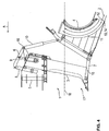
- the cable plow 1 comprises for forming a trough a suitable for engaging in the ground 17 sword 3 and a line guide 4 for inserting the line 2 in the formed by the sword 3 Erdrinne.
- the sword 3 is arranged in sections in a sword guide 5.
- a suspension 6 near the upper end of the sword 3 and cable guide 4 and a hinge lever 7 between the lower ends of the sword 3 and 4 line is provided.
- the wiring 4 is arranged in a designated direction A behind the sword 3.
- a first actuating cylinder 8 is provided for the simultaneous raising or lowering of the sword 3 and cable guide 4 in relation to the sword guide 5.
- a second actuating cylinder 9 is for raising or lowering the sword 3 and a third actuating cylinder 10 is provided for raising or lowering the wiring 4 in each case in relation to the sword guide 5.
- the cable guide 4 comprises a counter to the intended direction of travel A at the bottom, the sword 3 facing away from the end of the cable guide 4 ausmündenden duct 11, wherein the mouth portion 12 of the duct 11 downwardly bounding wall 13 forms a coating surface 14.
- the sword 3 has a cutting edge 15 at its lower end.
- the cutting edge 15 of the sword 3 extends substantially in a plane with the coating surface 14 of the cable guide 4, wherein the plane is substantially parallel to and above the terrain surface 16.
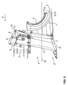
- the first actuating cylinder 8 is fixed at its upper end to the suspension 6 and near its lower end to the sword guide 5. A lifting movement of the first actuating cylinder 8 causes a raising or lowering of the sword 3 and wiring 4.
- the sword 3 and the cable guide 4 are simultaneously lowered by means of the first actuating cylinder 8, so that the cutting edge 15 of the sword 3 and the coating surface 14 of the cable guide 4 then substantially parallel to and below the terrain surface 16 in a plane.
- the second actuating cylinder 9 is fixed at its upper end to the suspension 6 and at its lower end to the sword 3.
- the blade 3 is lowered by means of the second actuating cylinder 4 to facilitate the penetration of the sword 3 and wiring 4 in the ground 17, so that the cutting edge 3 of the sword 4 with respect to Terrain surface 16 penetrates deeper into the ground 17.
- the third actuating cylinder 10 is attached to the suspension 6 near its upper end and to the conduit 4 near its lower end. A lifting movement of the third actuating cylinder 10 causes a raising or lowering of the Wiring 4. The wiring 4 is lowered to improve the insertion of the line 2 in the ground 17 by means of the third actuating cylinder 10 so that the coating surface 14 of the wiring 4 penetrates deeper into the ground 17 with respect to the terrain surface 16.
- the third actuating cylinder 10 is rotatably mounted at its upper end to the suspension 6 for adjusting the angle between the blade 3 and cable guide 4 via a hinge 18.
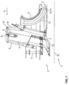
- FIG. 8 shows the embodiment according to FIG. 1 in all positions according to 1 to 7 and represents from right to left by way of example a possible timing of the method for operating the cable plow 1.
- An intended direction of travel of the cable plow 1 is designated by the reference symbol A.
- Sword 3 and wiring 4 are transferred from a first to a second position by sword 3 and wiring 4 are simultaneously lowered by means of the first actuating cylinder 8 in relation to the sword guide 5 and thus transferred to the working position, in the sword 3 and 4 line in the soil 17 have penetrated and thus the cutting edge 15 and the coating surface 14 extend below the terrain surface 16.
- the sword 3 is lowered by means of the second adjusting cylinder 9 relative to the sword guide 5, so that the cutting edge 15 of the sword 3 penetrates deeper into the ground 16 than the coating surface 14 of the cable guide. 4
- sword 3 and wiring 4 are transferred from the fourth to a fifth position by the third actuating cylinder 10 is pivoted so far in the direction of the sword 3 via the joint 18, that the cutting edge 15 of the sword 3 and the coating surface 14 of the wiring 4 parallel to each other.
- the coating surface 14 of the conduit 4 continues to run deeper in the ground 17 with respect to the terrain surface 16 than the cutting edge 15 of the sword 3.
- the sword 3 and cable guide 4 are transferred from the fifth to a sixth position by the cable guide 4 is raised by means of the second actuating cylinder 9 in relation to the sword guide 5, so that the cutting edge 15 of the sword 3 and the coating surface 14 of the wiring 4 in a Lie flat.
Landscapes
- Engineering & Computer Science (AREA)
- General Engineering & Computer Science (AREA)
- Mechanical Engineering (AREA)
- Mining & Mineral Resources (AREA)
- Civil Engineering (AREA)
- Structural Engineering (AREA)
- Laying Of Electric Cables Or Lines Outside (AREA)
Claims (15)
- Enfouisseuse de câbles (1) pour l'introduction d'au moins une ligne (2), en particulier au moins un tuyau ou un câble, dans le sol (17), dans laquelle l'enfouisseuse de câbles (1) présente une lame (3) appropriée pour s'enfoncer dans le sol (17) pour réaliser une tranchée, et un guide de ligne (4) pour mettre en place la ligne (2) dans la tranchée formée ou pouvant être formée par la lame (3), dans laquelle la lame (3) est agencée au moins partiellement dans un guide de lame (5), et
dans laquelle, pour relier la lame (3) et le guide de ligne (4), sont prévus un dispositif de suspension (6) à l'extrémité supérieure, ou à proximité de l'extrémité supérieure de la lame (3) et du guide de ligne (4), et
un levier d'articulation (7) entre les extrémités inférieures ou à proximité des extrémités inférieures de la lame (3) et du guide de ligne (4), et dans laquelle ledit guide de ligne (4) est disposé derrière la lame (3), dans une direction de déplacement prévue (A), caractérisée en ce que
trois vérins de manoeuvre (8; 9; 10) sont disposés au niveau du dispositif de suspension (6), avec un premier vérin de manoeuvre (8) prévu pour lever ou abaisser la lame (3) et le guide de ligne (4) en même temps par rapport au guide de lame (5),
un deuxième vérin de manoeuvre (9) prévu pour lever ou abaisser la lame (3) par rapport au guide de lame (5), et
un troisième vérin de manoeuvre (10) prévu pour lever ou abaisser le guide de ligne (4) par rapport au guide de lame (5). - Enfouisseuse de câbles selon la revendication 1,
caractérisée en ce que
ledit guide de ligne (4) présente un canal de ligne (11) débouchant dans le sens contraire à la direction de déplacement prévue (A), au niveau de l'extrémité du guide de ligne (4) opposée à la lame (3), dans laquelle la partie d'embouchure (12) du canal de ligne (11) forme une paroi (13) délimitant une surface d'étalement (14) vers le bas, et
dans laquelle la lame (3) présente un bord de coupe (15) à son extrémité inférieure. - Enfouisseuse de câbles selon la revendication 2,
caractérisé en ce que
dans une position de base des trois vérins de manoeuvre (8; 9; 10), le bord de coupe (15) de la lame (3) s'étend sensiblement dans un plan avec la surface d'étalement (14) du guide de ligne (4), dans laquelle le plan s'étend sensiblement parallèle à et au-dessus d'une surface supérieure de sol (16), et dans laquelle, dans une position de travail des trois vérins de manoeuvre (8; 9; 10), la lame (3) et le guide de ligne (4) sont introduits dans le sol (17), dans laquelle le bord de coupe (15) et la surface d'étalement (14) s'étendent le long ou en dessous de la surface supérieure de sol (16). - Enfouisseuse de câbles selon l'une quelconque des revendications précédentes,
caractérisée en ce que
le premier vérin de manoeuvre (8) est fixé au niveau de son extrémité supérieure ou à proximité de son extrémité supérieure au dispositif de suspension (6), et est fixé au niveau de son extrémité inférieure ou à proximité de son extrémité inférieure au guide de lame (5), dans laquelle une course du premier vérin de manoeuvre (8) fait monter ou descendre la lame (3) et le guide de ligne (4). - Enfouisseuse de câbles selon la revendication 4,
caractérisée en ce que
pour transférer la lame (3) et le guide de ligne (4) à partir de la position de base jusque dans la position de travail, la lame (3) et le guide de ligne (4) sont abaissés ou peuvent être abaissés simultanément au moyen du premier vérin de manoeuvre (8), de sorte que le bord de coupe (15) de la lame (3) et la surface d'étalement (14) du guide de ligne (4) s'étendent sensiblement dans un plan parallèlement à et le long ou au-dessous de la surface supérieure de sol (16). - Enfouisseuse de câbles selon la revendication 5,
caractérisée en ce que
pour transférer la lame (3) et le guide de ligne (4) à partir de la position de travail jusque dans la position de base, la lame (3) et le guide de ligne (4) sont abaissés ou peuvent être abaissés simultanément au moyen du premier vérin de manoeuvre (8), la lame (3) et le guide de ligne (4) étant extraits ou pouvant être extraits du sol (17). - Enfouisseuse de câbles selon l'une quelconque des revendications précédentes,
caractérisée en ce que
le deuxième vérin de manoeuvre (9) est fixé à son extrémité supérieure ou à proximité de son extrémité supérieure au dispositif de suspension (6), et est fixé à son extrémité inférieure ou à proximité de son extrémité inférieure à la lame (3), dans laquelle une course du deuxième vérin de manoeuvre (9) amène la lame (3) à se lever ou à s'abaisser. - Enfouisseuse de câbles selon la revendication 7,
caractérisée en ce que
pour faciliter la pénétration de la lame (3) et du guide de ligne (4) dans le sol (17), la lame (3) est abaissée ou peut être abaissée au moyen du deuxième vérin de manoeuvre (4), de sorte que le bord de coupe (3) de la lame (4), par rapport à la surface supérieure de sol (16), pénètre plus profondément dans le sol (17). - Enfouisseuse de câbles selon l'une quelconque des revendications précédentes,
caractérisée en ce que
le troisième cylindre d'actionnement (10) est fixé à son extrémité supérieure ou à proximité de son extrémité supérieure au dispositif de suspension (6), et est fixé à son extrémité inférieure ou à proximité de son extrémité inférieure au guide de ligne (4), dans laquelle une course du troisième vérin de manoeuvre (10) amène le guide de ligne (4) à se lever ou à s'abaisser. - Enfouisseuse de câbles selon la revendication 9,
caractérisée en ce que
pour améliorer l'insertion de la ligne (2) dans le sol (17), le guide de ligne (4) est abaissé ou peut être abaissé par l'intermédiaire du troisième vérin de manoeuvre (10), de sorte que la surface d'étalement (14) du guide de ligne (4), par rapport à la surface supérieure de sol (16), pénètre plus profondément dans le sol (17). - Enfouisseuse de câbles selon l'une quelconque des revendications précédentes,
caractérisée en ce que
le troisième vérin de manoeuvre (10) est fixé de manière rotative à son extrémité supérieure ou à proximité de son extrémité supérieure au dispositif de suspension (6) pour ajuster l'angle entre le bord de coupe (15) de la lame (3) et la surface d'étalement (14) du guide de ligne (4) par l'intermédiaire d'une articulation (18), et peut pivoter autour d'un axe de pivotement s'étendant à travers le centre de l'articulation (18). - Procédé pour faire fonctionner une enfouisseuse de câbles, en particulier une enfouisseuse de câbles selon l'une quelconque des revendications précédentes,
caractérisé en ce que
dans l'ordre prévu, la lame (3) et le guide de ligne (4) sont levés ou abaissés au moyen du premier vérin de manoeuvre (8),
la lame (3) est levée ou abaissée au moyen du deuxième vérin de manoeuvre (9),
le guide de ligne (4) est levé ou abaissé au moyen du troisième vérin de manoeuvre (10). - Procédé selon la revendication 12,
caractérisé en ce que
pour transférer la lame (3) et le guide de ligne (4) à partir de la position de base jusque dans la position de travail, la lame (3) et le guide de ligne (4) sont abaissés simultanément au moyen du premier vérin de manoeuvre (8), et
pour transférer la lame (3) et le guide de ligne (4) à partir de la position de travail jusque dans la position de base, la lame (3) et le guide de ligne (4) sont levés simultanément au moyen du premier vérin de manoeuvre (8). - Procédé selon la revendication 12 ou 13,
caractérisé en ce que
pour améliorer la pénétration de la lame (3) et du guide de ligne (4) dans le sol (17), premièrement la lame (3) est abaissée une ou plusieurs fois à la suite, puis le guide de ligne (4), le deuxième (8) et le troisième vérin de manoeuvre (8) effectuant une course une ou plusieurs fois à la suite. - Procédé selon l'une quelconque des revendications 12 à 14, caractérisé en ce que
pour améliorer l'extraction de la lame (3) et du guide de ligne (4) hors du sol, une ou plusieurs fois successivement et en alternance, premièrement le guide de ligne (4) et ensuite la lame (3) sont levés, le troisième (9) et le deuxième vérin de manoeuvre (8) effectuant une course une ou plusieurs fois successivement et en alternance.
Applications Claiming Priority (1)
| Application Number | Priority Date | Filing Date | Title |
|---|---|---|---|
| DE201310114087 DE102013114087B3 (de) | 2013-12-16 | 2013-12-16 | Kabelpflug |
Publications (2)
| Publication Number | Publication Date |
|---|---|
| EP2884607A1 EP2884607A1 (fr) | 2015-06-17 |
| EP2884607B1 true EP2884607B1 (fr) | 2016-07-06 |
Family
ID=52017611
Family Applications (1)
| Application Number | Title | Priority Date | Filing Date |
|---|---|---|---|
| EP14194261.5A Active EP2884607B1 (fr) | 2013-12-16 | 2014-11-21 | Enfouisseuse de câbles et procédé de fonctionnement d'une enfouisseuse de câbles |
Country Status (2)
| Country | Link |
|---|---|
| EP (1) | EP2884607B1 (fr) |
| DE (1) | DE102013114087B3 (fr) |
Families Citing this family (1)
| Publication number | Priority date | Publication date | Assignee | Title |
|---|---|---|---|---|
| DE102016106509B4 (de) * | 2016-04-08 | 2020-04-09 | Frank Föckersperger GmbH | Kabelpflug |
Family Cites Families (5)
| Publication number | Priority date | Publication date | Assignee | Title |
|---|---|---|---|---|
| AU416325B2 (en) * | 1966-10-05 | 1971-08-13 | Cable laying machine | |
| US4244123A (en) * | 1979-03-26 | 1981-01-13 | Germain Lazure | Guidance device for drain tile laying machine |
| DE4210858C2 (de) * | 1992-04-01 | 2001-05-10 | Walter Foeckersperger | Kabelpflug |
| US6189244B1 (en) * | 1999-09-15 | 2001-02-20 | Randal Johnson | Self-cleaning narrow ditch trencher and flexible tile installer |
| DE10115456B4 (de) * | 2001-03-29 | 2013-06-06 | Walter Föckersperger Jun. | Verlegepflug mit schürzenartiger Verdrängervorrichtung |
-
2013
- 2013-12-16 DE DE201310114087 patent/DE102013114087B3/de not_active Expired - Fee Related
-
2014
- 2014-11-21 EP EP14194261.5A patent/EP2884607B1/fr active Active
Also Published As
| Publication number | Publication date |
|---|---|
| EP2884607A1 (fr) | 2015-06-17 |
| DE102013114087B3 (de) | 2014-12-31 |
Similar Documents
| Publication | Publication Date | Title |
|---|---|---|
| EP3798367B1 (fr) | Élément d'ancrage sur une tranchée, son procédé de fonctionnement et procédé de construction souterraine | |
| EP3327203B1 (fr) | Dispositif de pose permettant la pose en terre de matériaux en fils flexibles | |
| EP1408163A2 (fr) | Engin de travaux public et procédé pour l'opération d'un tel engin | |
| EP3327204B1 (fr) | Dispositif de pose permettant la pose en terre de matériaux en fils flexibles | |
| DE102016103475B4 (de) | Landwirtschaftliches Vorsatzgerät | |
| DE102016225917B3 (de) | Wurzelballen-Unterschneide- und Aushebegerät | |
| DE102016106506B4 (de) | Kabelpflug | |
| DE2120740A1 (de) | Pflug | |
| EP3613900A1 (fr) | Machine de traitement du sol pourvue de dispositif de transport pouvant être rapidement enlevé du groupe de fraisage et procédé correspondant | |
| EP2884607B1 (fr) | Enfouisseuse de câbles et procédé de fonctionnement d'une enfouisseuse de câbles | |
| DE202016101871U1 (de) | Kabelpflug | |
| EP2378001B1 (fr) | Dispositif de traitement de sol | |
| DE102016111012B4 (de) | Kabelpflug | |
| DE102020118288B4 (de) | Kabelpflugsystem | |
| EP1630301B1 (fr) | Procédé et dispositif pour le travail du sol | |
| EP3725950B1 (fr) | Benne de forage et procédé de fabrication d'une parois dans le sol | |
| EP0157337B1 (fr) | Outil pour l'ameublissement | |
| DE202024103958U1 (de) | Kabelpflug | |
| DE202013105701U1 (de) | Kabelpflug | |
| DE3128467A1 (de) | Verfahren und vorrichtung zum roden von baumstuempfen | |
| EP3323283A1 (fr) | Bras ainsi qu'un appareil de travail à bras muni d'un tel bras | |
| EP3792407A1 (fr) | Dispositif de pose pour la pose de matériaux en brins flexibles dans le sol et dispositif d'insertion principale pour un tel dispositif de pose | |
| DE2639014C3 (de) | Vorrichtung zum Verlegen von Erdkabeln u.dgl | |
| DE102016106509B4 (de) | Kabelpflug | |
| DE3245623A1 (de) | Gelaendegaengiges, lenkbares fahrgestell |
Legal Events
| Date | Code | Title | Description |
|---|---|---|---|
| PUAI | Public reference made under article 153(3) epc to a published international application that has entered the european phase |
Free format text: ORIGINAL CODE: 0009012 |
|
| 17P | Request for examination filed |
Effective date: 20141121 |
|
| AK | Designated contracting states |
Kind code of ref document: A1 Designated state(s): AL AT BE BG CH CY CZ DE DK EE ES FI FR GB GR HR HU IE IS IT LI LT LU LV MC MK MT NL NO PL PT RO RS SE SI SK SM TR |
|
| AX | Request for extension of the european patent |
Extension state: BA ME |
|
| R17P | Request for examination filed (corrected) |
Effective date: 20150921 |
|
| RBV | Designated contracting states (corrected) |
Designated state(s): AL AT BE BG CH CY CZ DE DK EE ES FI FR GB GR HR HU IE IS IT LI LT LU LV MC MK MT NL NO PL PT RO RS SE SI SK SM TR |
|
| GRAP | Despatch of communication of intention to grant a patent |
Free format text: ORIGINAL CODE: EPIDOSNIGR1 |
|
| INTG | Intention to grant announced |
Effective date: 20160202 |
|
| GRAS | Grant fee paid |
Free format text: ORIGINAL CODE: EPIDOSNIGR3 |
|
| GRAA | (expected) grant |
Free format text: ORIGINAL CODE: 0009210 |
|
| AK | Designated contracting states |
Kind code of ref document: B1 Designated state(s): AL AT BE BG CH CY CZ DE DK EE ES FI FR GB GR HR HU IE IS IT LI LT LU LV MC MK MT NL NO PL PT RO RS SE SI SK SM TR |
|
| REG | Reference to a national code |
Ref country code: GB Ref legal event code: FG4D Free format text: NOT ENGLISH |
|
| REG | Reference to a national code |
Ref country code: AT Ref legal event code: REF Ref document number: 811301 Country of ref document: AT Kind code of ref document: T Effective date: 20160715 Ref country code: CH Ref legal event code: EP |
|
| REG | Reference to a national code |
Ref country code: IE Ref legal event code: FG4D Free format text: LANGUAGE OF EP DOCUMENT: GERMAN |
|
| REG | Reference to a national code |
Ref country code: DE Ref legal event code: R096 Ref document number: 502014001051 Country of ref document: DE |
|
| REG | Reference to a national code |
Ref country code: NL Ref legal event code: MP Effective date: 20160706 |
|
| REG | Reference to a national code |
Ref country code: LT Ref legal event code: MG4D |
|
| PG25 | Lapsed in a contracting state [announced via postgrant information from national office to epo] |
Ref country code: IS Free format text: LAPSE BECAUSE OF FAILURE TO SUBMIT A TRANSLATION OF THE DESCRIPTION OR TO PAY THE FEE WITHIN THE PRESCRIBED TIME-LIMIT Effective date: 20161106 Ref country code: HR Free format text: LAPSE BECAUSE OF FAILURE TO SUBMIT A TRANSLATION OF THE DESCRIPTION OR TO PAY THE FEE WITHIN THE PRESCRIBED TIME-LIMIT Effective date: 20160706 Ref country code: NO Free format text: LAPSE BECAUSE OF FAILURE TO SUBMIT A TRANSLATION OF THE DESCRIPTION OR TO PAY THE FEE WITHIN THE PRESCRIBED TIME-LIMIT Effective date: 20161006 Ref country code: RS Free format text: LAPSE BECAUSE OF FAILURE TO SUBMIT A TRANSLATION OF THE DESCRIPTION OR TO PAY THE FEE WITHIN THE PRESCRIBED TIME-LIMIT Effective date: 20160706 Ref country code: FI Free format text: LAPSE BECAUSE OF FAILURE TO SUBMIT A TRANSLATION OF THE DESCRIPTION OR TO PAY THE FEE WITHIN THE PRESCRIBED TIME-LIMIT Effective date: 20160706 Ref country code: LT Free format text: LAPSE BECAUSE OF FAILURE TO SUBMIT A TRANSLATION OF THE DESCRIPTION OR TO PAY THE FEE WITHIN THE PRESCRIBED TIME-LIMIT Effective date: 20160706 Ref country code: IT Free format text: LAPSE BECAUSE OF FAILURE TO SUBMIT A TRANSLATION OF THE DESCRIPTION OR TO PAY THE FEE WITHIN THE PRESCRIBED TIME-LIMIT Effective date: 20160706 Ref country code: NL Free format text: LAPSE BECAUSE OF FAILURE TO SUBMIT A TRANSLATION OF THE DESCRIPTION OR TO PAY THE FEE WITHIN THE PRESCRIBED TIME-LIMIT Effective date: 20160706 |
|
| PG25 | Lapsed in a contracting state [announced via postgrant information from national office to epo] |
Ref country code: ES Free format text: LAPSE BECAUSE OF FAILURE TO SUBMIT A TRANSLATION OF THE DESCRIPTION OR TO PAY THE FEE WITHIN THE PRESCRIBED TIME-LIMIT Effective date: 20160706 Ref country code: LV Free format text: LAPSE BECAUSE OF FAILURE TO SUBMIT A TRANSLATION OF THE DESCRIPTION OR TO PAY THE FEE WITHIN THE PRESCRIBED TIME-LIMIT Effective date: 20160706 Ref country code: PT Free format text: LAPSE BECAUSE OF FAILURE TO SUBMIT A TRANSLATION OF THE DESCRIPTION OR TO PAY THE FEE WITHIN THE PRESCRIBED TIME-LIMIT Effective date: 20161107 Ref country code: BE Free format text: LAPSE BECAUSE OF NON-PAYMENT OF DUE FEES Effective date: 20161130 Ref country code: GR Free format text: LAPSE BECAUSE OF FAILURE TO SUBMIT A TRANSLATION OF THE DESCRIPTION OR TO PAY THE FEE WITHIN THE PRESCRIBED TIME-LIMIT Effective date: 20161007 Ref country code: PL Free format text: LAPSE BECAUSE OF FAILURE TO SUBMIT A TRANSLATION OF THE DESCRIPTION OR TO PAY THE FEE WITHIN THE PRESCRIBED TIME-LIMIT Effective date: 20160706 Ref country code: SE Free format text: LAPSE BECAUSE OF FAILURE TO SUBMIT A TRANSLATION OF THE DESCRIPTION OR TO PAY THE FEE WITHIN THE PRESCRIBED TIME-LIMIT Effective date: 20160706 |
|
| REG | Reference to a national code |
Ref country code: DE Ref legal event code: R097 Ref document number: 502014001051 Country of ref document: DE |
|
| PG25 | Lapsed in a contracting state [announced via postgrant information from national office to epo] |
Ref country code: RO Free format text: LAPSE BECAUSE OF FAILURE TO SUBMIT A TRANSLATION OF THE DESCRIPTION OR TO PAY THE FEE WITHIN THE PRESCRIBED TIME-LIMIT Effective date: 20160706 Ref country code: EE Free format text: LAPSE BECAUSE OF FAILURE TO SUBMIT A TRANSLATION OF THE DESCRIPTION OR TO PAY THE FEE WITHIN THE PRESCRIBED TIME-LIMIT Effective date: 20160706 |
|
| PLBE | No opposition filed within time limit |
Free format text: ORIGINAL CODE: 0009261 |
|
| STAA | Information on the status of an ep patent application or granted ep patent |
Free format text: STATUS: NO OPPOSITION FILED WITHIN TIME LIMIT |
|
| PG25 | Lapsed in a contracting state [announced via postgrant information from national office to epo] |
Ref country code: CZ Free format text: LAPSE BECAUSE OF FAILURE TO SUBMIT A TRANSLATION OF THE DESCRIPTION OR TO PAY THE FEE WITHIN THE PRESCRIBED TIME-LIMIT Effective date: 20160706 Ref country code: SM Free format text: LAPSE BECAUSE OF FAILURE TO SUBMIT A TRANSLATION OF THE DESCRIPTION OR TO PAY THE FEE WITHIN THE PRESCRIBED TIME-LIMIT Effective date: 20160706 Ref country code: BG Free format text: LAPSE BECAUSE OF FAILURE TO SUBMIT A TRANSLATION OF THE DESCRIPTION OR TO PAY THE FEE WITHIN THE PRESCRIBED TIME-LIMIT Effective date: 20161006 Ref country code: SK Free format text: LAPSE BECAUSE OF FAILURE TO SUBMIT A TRANSLATION OF THE DESCRIPTION OR TO PAY THE FEE WITHIN THE PRESCRIBED TIME-LIMIT Effective date: 20160706 Ref country code: DK Free format text: LAPSE BECAUSE OF FAILURE TO SUBMIT A TRANSLATION OF THE DESCRIPTION OR TO PAY THE FEE WITHIN THE PRESCRIBED TIME-LIMIT Effective date: 20160706 |
|
| 26N | No opposition filed |
Effective date: 20170407 |
|
| REG | Reference to a national code |
Ref country code: IE Ref legal event code: MM4A |
|
| REG | Reference to a national code |
Ref country code: FR Ref legal event code: ST Effective date: 20170731 |
|
| PG25 | Lapsed in a contracting state [announced via postgrant information from national office to epo] |
Ref country code: SI Free format text: LAPSE BECAUSE OF FAILURE TO SUBMIT A TRANSLATION OF THE DESCRIPTION OR TO PAY THE FEE WITHIN THE PRESCRIBED TIME-LIMIT Effective date: 20160706 |
|
| PG25 | Lapsed in a contracting state [announced via postgrant information from national office to epo] |
Ref country code: LU Free format text: LAPSE BECAUSE OF NON-PAYMENT OF DUE FEES Effective date: 20161130 |
|
| PG25 | Lapsed in a contracting state [announced via postgrant information from national office to epo] |
Ref country code: FR Free format text: LAPSE BECAUSE OF NON-PAYMENT OF DUE FEES Effective date: 20161130 |
|
| PG25 | Lapsed in a contracting state [announced via postgrant information from national office to epo] |
Ref country code: IE Free format text: LAPSE BECAUSE OF NON-PAYMENT OF DUE FEES Effective date: 20161121 |
|
| REG | Reference to a national code |
Ref country code: BE Ref legal event code: MM Effective date: 20161130 |
|
| PG25 | Lapsed in a contracting state [announced via postgrant information from national office to epo] |
Ref country code: HU Free format text: LAPSE BECAUSE OF FAILURE TO SUBMIT A TRANSLATION OF THE DESCRIPTION OR TO PAY THE FEE WITHIN THE PRESCRIBED TIME-LIMIT; INVALID AB INITIO Effective date: 20141121 |
|
| PG25 | Lapsed in a contracting state [announced via postgrant information from national office to epo] |
Ref country code: CY Free format text: LAPSE BECAUSE OF FAILURE TO SUBMIT A TRANSLATION OF THE DESCRIPTION OR TO PAY THE FEE WITHIN THE PRESCRIBED TIME-LIMIT Effective date: 20160706 Ref country code: MK Free format text: LAPSE BECAUSE OF FAILURE TO SUBMIT A TRANSLATION OF THE DESCRIPTION OR TO PAY THE FEE WITHIN THE PRESCRIBED TIME-LIMIT Effective date: 20160706 Ref country code: MC Free format text: LAPSE BECAUSE OF FAILURE TO SUBMIT A TRANSLATION OF THE DESCRIPTION OR TO PAY THE FEE WITHIN THE PRESCRIBED TIME-LIMIT Effective date: 20160706 |
|
| PG25 | Lapsed in a contracting state [announced via postgrant information from national office to epo] |
Ref country code: LI Free format text: LAPSE BECAUSE OF NON-PAYMENT OF DUE FEES Effective date: 20171130 Ref country code: CH Free format text: LAPSE BECAUSE OF NON-PAYMENT OF DUE FEES Effective date: 20171130 |
|
| PG25 | Lapsed in a contracting state [announced via postgrant information from national office to epo] |
Ref country code: MT Free format text: LAPSE BECAUSE OF FAILURE TO SUBMIT A TRANSLATION OF THE DESCRIPTION OR TO PAY THE FEE WITHIN THE PRESCRIBED TIME-LIMIT Effective date: 20160706 |
|
| PG25 | Lapsed in a contracting state [announced via postgrant information from national office to epo] |
Ref country code: TR Free format text: LAPSE BECAUSE OF FAILURE TO SUBMIT A TRANSLATION OF THE DESCRIPTION OR TO PAY THE FEE WITHIN THE PRESCRIBED TIME-LIMIT Effective date: 20160706 Ref country code: AL Free format text: LAPSE BECAUSE OF FAILURE TO SUBMIT A TRANSLATION OF THE DESCRIPTION OR TO PAY THE FEE WITHIN THE PRESCRIBED TIME-LIMIT Effective date: 20160706 |
|
| P01 | Opt-out of the competence of the unified patent court (upc) registered |
Effective date: 20230512 |
|
| PGFP | Annual fee paid to national office [announced via postgrant information from national office to epo] |
Ref country code: DE Payment date: 20251127 Year of fee payment: 12 |
|
| PGFP | Annual fee paid to national office [announced via postgrant information from national office to epo] |
Ref country code: GB Payment date: 20251125 Year of fee payment: 12 |
|
| PGFP | Annual fee paid to national office [announced via postgrant information from national office to epo] |
Ref country code: AT Payment date: 20250917 Year of fee payment: 12 |