EP2884683A1 - Parametereinstellverfahren, endgerät und basisstation in einem datenübertragungsdienst - Google Patents
Parametereinstellverfahren, endgerät und basisstation in einem datenübertragungsdienst Download PDFInfo
- Publication number
- EP2884683A1 EP2884683A1 EP13842700.0A EP13842700A EP2884683A1 EP 2884683 A1 EP2884683 A1 EP 2884683A1 EP 13842700 A EP13842700 A EP 13842700A EP 2884683 A1 EP2884683 A1 EP 2884683A1
- Authority
- EP
- European Patent Office
- Prior art keywords
- packet
- terminal
- time
- base station
- playing
- Prior art date
- Legal status (The legal status is an assumption and is not a legal conclusion. Google has not performed a legal analysis and makes no representation as to the accuracy of the status listed.)
- Withdrawn
Links
- 230000005540 biological transmission Effects 0.000 title claims abstract description 106
- 238000000034 method Methods 0.000 title claims abstract description 65
- 230000004083 survival effect Effects 0.000 claims abstract description 126
- 230000003139 buffering effect Effects 0.000 claims description 45
- 230000006399 behavior Effects 0.000 claims description 17
- 101000635761 Homo sapiens Receptor-transporting protein 3 Proteins 0.000 description 9
- 102100030849 Receptor-transporting protein 3 Human genes 0.000 description 9
- 230000000694 effects Effects 0.000 description 7
- 238000010586 diagram Methods 0.000 description 4
- 230000007774 longterm Effects 0.000 description 2
- 238000012986 modification Methods 0.000 description 2
- 230000004048 modification Effects 0.000 description 2
- 238000005516 engineering process Methods 0.000 description 1
- 230000003287 optical effect Effects 0.000 description 1
Images


Classifications
-
- H—ELECTRICITY
- H04—ELECTRIC COMMUNICATION TECHNIQUE
- H04L—TRANSMISSION OF DIGITAL INFORMATION, e.g. TELEGRAPHIC COMMUNICATION
- H04L47/00—Traffic control in data switching networks
- H04L47/10—Flow control; Congestion control
- H04L47/28—Flow control; Congestion control in relation to timing considerations
- H04L47/286—Time to live
-
- H—ELECTRICITY
- H04—ELECTRIC COMMUNICATION TECHNIQUE
- H04L—TRANSMISSION OF DIGITAL INFORMATION, e.g. TELEGRAPHIC COMMUNICATION
- H04L1/00—Arrangements for detecting or preventing errors in the information received
- H04L1/0001—Systems modifying transmission characteristics according to link quality, e.g. power backoff
- H04L1/0023—Systems modifying transmission characteristics according to link quality, e.g. power backoff characterised by the signalling
- H04L1/0026—Transmission of channel quality indication
-
- H—ELECTRICITY
- H04—ELECTRIC COMMUNICATION TECHNIQUE
- H04L—TRANSMISSION OF DIGITAL INFORMATION, e.g. TELEGRAPHIC COMMUNICATION
- H04L1/00—Arrangements for detecting or preventing errors in the information received
- H04L1/12—Arrangements for detecting or preventing errors in the information received by using return channel
- H04L1/16—Arrangements for detecting or preventing errors in the information received by using return channel in which the return channel carries supervisory signals, e.g. repetition request signals
- H04L1/1607—Details of the supervisory signal
- H04L1/1671—Details of the supervisory signal the supervisory signal being transmitted together with control information
- H04L1/1678—Details of the supervisory signal the supervisory signal being transmitted together with control information where the control information is for timing, e.g. time stamps
-
- H—ELECTRICITY
- H04—ELECTRIC COMMUNICATION TECHNIQUE
- H04L—TRANSMISSION OF DIGITAL INFORMATION, e.g. TELEGRAPHIC COMMUNICATION
- H04L1/00—Arrangements for detecting or preventing errors in the information received
- H04L1/12—Arrangements for detecting or preventing errors in the information received by using return channel
- H04L1/16—Arrangements for detecting or preventing errors in the information received by using return channel in which the return channel carries supervisory signals, e.g. repetition request signals
- H04L1/18—Automatic repetition systems, e.g. Van Duuren systems
- H04L1/1822—Automatic repetition systems, e.g. Van Duuren systems involving configuration of automatic repeat request [ARQ] with parallel processes
-
- H—ELECTRICITY
- H04—ELECTRIC COMMUNICATION TECHNIQUE
- H04L—TRANSMISSION OF DIGITAL INFORMATION, e.g. TELEGRAPHIC COMMUNICATION
- H04L1/00—Arrangements for detecting or preventing errors in the information received
- H04L1/12—Arrangements for detecting or preventing errors in the information received by using return channel
- H04L1/16—Arrangements for detecting or preventing errors in the information received by using return channel in which the return channel carries supervisory signals, e.g. repetition request signals
- H04L1/18—Automatic repetition systems, e.g. Van Duuren systems
- H04L1/1829—Arrangements specially adapted for the receiver end
- H04L1/1835—Buffer management
- H04L1/1838—Buffer management for semi-reliable protocols, e.g. for less sensitive applications such as streaming video
-
- H—ELECTRICITY
- H04—ELECTRIC COMMUNICATION TECHNIQUE
- H04W—WIRELESS COMMUNICATION NETWORKS
- H04W28/00—Network traffic management; Network resource management
- H04W28/16—Central resource management; Negotiation of resources or communication parameters, e.g. negotiating bandwidth or QoS [Quality of Service]
- H04W28/18—Negotiating wireless communication parameters
-
- H—ELECTRICITY
- H04—ELECTRIC COMMUNICATION TECHNIQUE
- H04W—WIRELESS COMMUNICATION NETWORKS
- H04W72/00—Local resource management
- H04W72/50—Allocation or scheduling criteria for wireless resources
- H04W72/54—Allocation or scheduling criteria for wireless resources based on quality criteria
- H04W72/543—Allocation or scheduling criteria for wireless resources based on quality criteria based on requested quality, e.g. QoS
Definitions
- the present invention relates to wireless communications technologies, and in particular, to a method for setting a parameter in a data transmission service, a terminal, and a base station.
- an air interface protocol stack between a user equipment (User Equipment, UE) and an evolved NodeB (evolved NodeB, eNodeB) includes a user plane and a control plane.
- a user plane protocol stack includes a physical layer, a Media Access Control (Media Access Control, MAC) layer, a Radio Link Control (Radio Link Control, RLC) layer, and a Packet Data Convergence Protocol (Packet Data Convergence Protocol, PDCP) layer; and the control plane further includes a Radio Resource Control (Radio Resource Control, RRC) layer in addition to the foregoing architectures.
- RRC Radio Resource Control
- an RRC entity needs to configure parameters for a PDCP entity.
- One of the parameters is duration of a discard timer at the PDCP layer, and the duration may be 50ms, 100ms, 150ms, 300ms, 500ms, 700ms, 1500ms, or infinite.
- the PDCP entity configures one discard timer for each service data unit (Service Data Unit, SDU).
- SDU Service Data Unit
- the PDCP entity discards the corresponding SDU and a corresponding protocol data unit (Protocol Data Unit, PDU). If the corresponding PDU has been delivered to a lower layer, the PDCP entity sends a discarding instruction command to the lower layer.
- PDU Protocol Data Unit
- the foregoing duration of the discard timer at the PDCP layer is set according to a quality of service (Quality of Service, QoS) requirement for network transmission.
- QoS Quality of Service
- the QoS requirement can be met as a whole only, but a related parameter cannot be dynamically set, and therefore user experience cannot be ensured either.
- embodiments of the present invention provide a method for setting a parameter in a data transmission service, a terminal, and a base station, so as to solve a problem in the prior art that user experience cannot be ensured.
- a method for setting a parameter in a data transmission service includes:
- the determining time-to-live of a packet on a network node according to a terminal status includes:
- the method before the sending, by the terminal, a survival report to a base station, the method further includes:
- the triggering event includes any one of the following items:
- the method before the sending, by the terminal, a survival report to a base station, the method further includes:
- the triggering message is sent after the base station detects a packet loss in at least one of the following layers: a Packet Data Convergence Protocol PDCP layer, a Radio Link Control RLC layer, and a Radio Link Control MAC layer; or the triggering message is sent after the base station detects a cell handover of the terminal.
- a Packet Data Convergence Protocol PDCP layer a Packet Data Convergence Protocol PDCP layer, a Radio Link Control RLC layer, and a Radio Link Control MAC layer
- the triggering message is sent after the base station detects a cell handover of the terminal.
- the survival report further includes information about a triggering event that has occurred, so that the base station further sets the packet transmission parameter according to the information about the triggering event that has occurred.
- the time-to-live is time-to-live of a first packet
- the survival report further includes identification information of the first packet
- the first packet is a next packet that needs to be received by the terminal, so that the base station transmits the first packet within the time-to-live according to the packet transmission parameter.
- the packet transmission parameter includes at least one of the following items:
- a method for setting a parameter in a data transmission service includes:
- the method before the receiving, by a base station, a survival report sent by a terminal, the method further includes:
- the triggering event includes any one of the following items:
- the method before the receiving, by a base station, a survival report sent by a terminal, the method further includes:
- the sending, by the base station, a triggering message to the terminal includes:
- the survival report further includes information about a triggering event that has occurred, so that the base station further sets the packet transmission parameter according to the information about the triggering event that has occurred.
- the survival report further includes identification information of a first packet, the first packet is a next packet that needs to be received by the terminal, and the method further includes:
- the packet transmission parameter includes at least one of the following items:
- a terminal where the terminal includes:
- the processor is specifically configured to:
- the terminal further includes:
- the triggering event includes any one of the following items:
- the terminal further includes:
- the triggering message received by the second receiver is sent after the base station detects a packet loss in at least one of the following layers: a Packet Data Convergence Protocol PDCP layer, a Radio Link Control RLC layer, and a Radio Link Control MAC layer; or the triggering message is sent after the base station detects a cell handover of the terminal.
- the survival report sent by the sender further includes information about a triggering event that has occurred, so that the base station further sets the packet transmission parameter according to the information about the triggering event that has occurred.
- the time-to-live determined by the processor is time-to-live of a first packet
- the survival report sent by the sender further includes identification information of the first packet
- the first packet is a next packet that needs to be received by the terminal, so that the base station transmits the first packet within the time-to-live according to the packet transmission parameter.
- the packet transmission parameter includes at least one of the following items:
- a base station where the base station includes:
- the base station further includes:
- the triggering event includes any one of the following items:
- the base station further includes:
- the processor is further configured to detect the following event: a packet loss occurs in at least one of the following layers: a Packet Data Convergence Protocol PDCP layer, a Radio Link Control RLC layer, and a Radio Link Control MAC layer; or a cell handover of the terminal occurs; and the second sender is specifically configured to send the triggering message when the processor detects the event.
- a packet loss occurs in at least one of the following layers: a Packet Data Convergence Protocol PDCP layer, a Radio Link Control RLC layer, and a Radio Link Control MAC layer; or a cell handover of the terminal occurs; and the second sender is specifically configured to send the triggering message when the processor detects the event.
- the survival report received by the receiver further includes information about a triggering event that has occurred, so that the base station further sets the packet transmission parameter according to the information about the triggering event that has occurred.
- the survival report further includes identification information of a first packet
- the base station further includes:
- the packet transmission parameter includes at least one of the following items:
- a terminal determines time-to-live according to a current situation of a packet, and can dynamically determine the time-to-live and send the time-to-live to a base station.
- the base station sets a related parameter according to the time-to-live, and then, when the base station transmits the packet according to the related parameter, a user experience effect can be ensured.
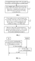
- FIG. 1 is a schematic flowchart of an embodiment of a method for setting a parameter in a data transmission service according to the present invention, where the method includes:
- Step 11 A terminal determines time-to-live of a packet on a network node according to a terminal status, where the terminal status is time, which can be maintained, for playing a currently buffered packet, or the terminal status includes a triggering event and time, which can be maintained, for playing a currently buffered packet; it may be that, when the terminal status is the time, which can be maintained, for playing the currently buffered packet, the time-to-live is determined according to time for which currently playing a video frame lasts and time, which can be maintained, for playing a remaining packet in a buffer except the video frame that is currently played, or the time-to-live is determined according to time, which can be maintained, for playing a remaining packet in a buffer except the video frame that is currently played; or, when the terminal status includes the triggering event and the time, which can be maintained, for playing the currently buffered packet, the time-to-live is determined according to the triggering event of the terminal, time for which currently playing a video frame lasts, and time, which can
- a sum of the time for which currently playing the video frame lasts and the time, which can be maintained, for playing the remaining packet in the buffer except the video frame that is currently played is determined as the time-to-live; or the time, which can be maintained, for playing the remaining packet in the buffer except the video frame that is currently played is determined as the time-to-live.
- T sur time for which the terminal currently plays a video frame lasts
- t 2 time, which can be maintained, for playing a remaining packet in a buffer of the terminal except the video frame that is currently played
- the terminal may first buffer a packet that is downloaded from a network side, where the packet may include one or more video frames; afterwards the terminal may acquire a video frame from the buffer for playing.
- a packet in the buffer except the video frame that is currently played is a remaining packet.
- Each video frame has standard playing time. For example, if time for playing each video frame is 0.3ms, time for which a current video frame lasts is 0.3ms, and time, which can be maintained, for playing a remaining packet may be determined according to the number of video frames in the remaining packet and standard time. For example, if data of the video frames in the remaining packet is N, the time, which can be maintained, for playing the remaining packet is Nx0.3ms.
- the time-to-live is equal to a playing time interval between a current playing point to the last valid packet in the buffer, and is equal to a maximum transmission delay of a next unreceived packet; or the time-to-live is simplified as the time, which can be maintained, for playing the remaining packet.
- the time-to-live may also be determined according to the triggering event in addition to the foregoing time, which can be maintained, for playing the currently buffered packet.
- an amount of time to be added to or subtracted from t 1 + t 2 or t 2 may also be set.
- Step 12 The terminal sends a survival report to a base station, where the survival report includes the time-to-live, so that the base station sets a packet transmission parameter according to the time-to-live.
- the base station may transmit the packet according to the packet transmission parameter.
- the packet transmission parameter may include at least one of the following items:
- the base station may set time that has a smallest error when compared with the time-to-live as the duration of the discard timer at the PDCP layer, where the time is among configurable time such as 50ms, 100ms, 150ms, 300ms, 500ms, 700ms, 1500ms, or infinite; and afterwards, the base station may perform packet discarding processing according to the duration; or the base station divides, according to the time-to-live, the time-to-live by packet retransmission time to obtain the maximum number of retransmissions; and afterwards, the base station may retransmit the packet before the maximum number of retransmissions is exceeded; or the user scheduling policy includes a scheduling priority and a radio resource; when the time-to-live is relatively short, a higher scheduling priority is set, and more radio resources are allocated; when the time-to-live is relatively long, a lower scheduling priority is set, and fewer radio resources are allocated; and afterwards, the base station may perform packet scheduling and transmission according to the scheduling policy.
- the time
- steps executed on a base station side may include:
- Step 21 A base station receives a survival report sent by a terminal, where the survival report includes time-to-live of a packet on a network node, the time-to-live is determined by the terminal according to a terminal status, and the terminal status is time, which can be maintained, for playing a currently buffered packet, or the terminal status includes a triggering event and time, which can be maintained, for playing a currently buffered packet.
- Step 22 The base station sets a packet transmission parameter according to the time-to-live, so that the base station transmits the packet according to the packet transmission parameter.
- a terminal determines time-to-live according to a current situation of a packet, and can dynamically determine the time-to-live and send the time-to-live to a base station.
- the base station sets a related parameter according to the time-to-live, and then, when the base station transmits the packet according to the related parameter, it is ensured, to the largest extent, that the packet can be effectively sent to the terminal; therefore, a user experience effect can be ensured.
- the terminal and the base station have different names.
- the terminal may be an MS, a UE, or the like
- the base station may be a NodeB, an eNodeB, or the like.
- a UE and an eNodeB are used as examples in embodiments of the present invention for description.
- FIG. 3a is a schematic flowchart of another embodiment of a method for setting a parameter in a data transmission service according to the present invention.
- a reporting policy and a survival report are configured on a UE is used as an example.
- This embodiment includes:
- Step 31 Configure a reporting policy on a UE, where the reporting policy includes information about a triggering event.
- the reporting policy is used to instruct a terminal to report, when the triggering event occurs, a survival report, so that the terminal reports the survival report when the triggering event occurs.
- the triggering event may include at least one of the following items:
- Step 32 The UE determines time-to-live.
- step 11 For specific content, reference may be made to step 11.
- Step 33 The UE sends a survival report to an eNodeB according to the configured reporting policy, where the report includes the time-to-live.
- the UE when the reporting policy is reporting according to a reporting period, the UE reports the survival report when the reporting period arrives; or when the reporting policy is that buffered data is blank, the UE reports the survival report when the buffered data is blank.
- the survival report may further include information about a triggering event that has occurred, and the triggering event that has occurred includes any one of the following items:
- Step 34 The eNodeB sets a data transmission parameter according to the time-to-live, where the data transmission parameter may include at least one of the following items:
- step 12 For a specific setting method, reference may be made to step 12.
- the information, which is reported by the terminal, about the triggering event may be used as another reference for adjusting the data transmission parameter.
- the triggering event is a playing stop due to a user behavior, because a user does not play a video in this case, it may be considered that the time-to-live is appropriately increased, or the time-to-live is set to a maximum value, and until the terminal instructs to start playing, the data transmission parameter is set according to the reported time-to-live.
- Step 35 The eNodeB sends data to the UE according to the data transmission parameter.
- data is discarded after the discard timer at the PDCP layer expires, or data is retransmitted before the maximum number of retransmissions is exceeded, and data is discarded when the maximum number of retransmissions is exceeded, or data is transmitted on a set radio resource according to a set priority sequence.
- a UE triggers reporting of a survival report, so that an eNodeB can dynamically set a related parameter according to time-to-live, so as to satisfy a user experience effect.
- the following parameter setting may be performed.
- this embodiment includes:
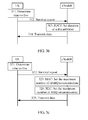
- Step 311 A UE determines time-to-live (Survivor Time Estimation).
- Step 312 The UE sends a survival report to an eNodeB, where the survival report carries the time-to-live (SurvivorTimeReporting).
- Step 313 Set duration of a discard timer at a PDCP layer of the eNodeB according to the time-to-live (PDCP: DiscardTimer Configuration).
- PDCP DiscardTimer Configuration
- Step 314 The eNodeB transmits data according to the set duration of the discard timer (Data Transmission).
- this embodiment includes:
- Step 321 A UE determines time-to-live (Survivor Time Estimation).
- Step 322 The UE sends a survival report to an eNodeB, where the survival report carries the time-to-live (SurvivorTimeReporting).
- Step 323 Set the maximum number of HARQ retransmissions at a MAC layer of the eNodeB according to the time-to-live (MAC: maxHARQ Configuration).
- Step 324 Set the maximum number of ARQ retransmissions at an RLC layer of the eNodeB according to the time-to-live (RLC: maxRetxThreshold Configuration).
- Step 325 The eNodeB transmits data according to the set maximum number of HARQ retransmissions and/or the set maximum number of ARQ retransmissions (Data Transmission).
- FIG. 4a is a schematic flowchart of another embodiment of a method for setting a parameter in a data transmission service according to the present invention.
- an eNodeB sends a configuration message to a UE, and the UE reports a survival report according to the configuration message is used as an example.
- This embodiment includes:
- Step 41 An eNodeB sends a configuration message to a UE, where the configuration message includes information about a triggering event.
- the configuration message is used to instruct a terminal to report, when a triggering event occurs, a survival report, so that the terminal reports the survival report when the triggering event occurs.
- the triggering event may include at least one of the following items:
- Step 42 The UE determines time-to-live.
- Step 43 The UE sends a survival report to the eNodeB according to the configuration message, where the report includes the time-to-live.
- the survival report is reported when the reporting period arrives; or when the configuration message includes that buffered data is blank, the survival report is reported when the buffered data is blank.
- the survival report may further include information about a triggering event that has occurred, and the triggering event that has occurred includes any one of the following items:
- Step 44 The eNodeB sets a data transmission parameter according to the time-to-live, where the data transmission parameter may include at least one of the following items:
- Step 45 The eNodeB sends data to the UE according to the data transmission parameter.
- step 42 For specific content of step 42, step 44, and step 45, reference may be made to step 32, step 34, and step 35.
- an eNodeB sends configuration information to a UE, and the UE triggers, according to the configuration information, reporting of a survival report, so that the eNodeB can dynamically set a related parameter according to time-to-live, so as to satisfy a user experience effect.
- the following parameter setting may be performed.
- this embodiment includes:
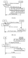
- Step 411 An eNodeB sends a configuration message to a UE (SurvivorTimeConfiguration).
- Step 412 The UE determines time-to-live (Survivor Time Estimation).
- Step 413 The UE sends a survival report to the eNodeB according to the configuration message, where the survival report carries the time-to-live (SurvivorTimeReporting).
- Step 414 Set duration of a discard timer at a PDCP layer of the eNodeB according to the time-to-live (PDCP: DiscardTimer Configuration).
- PDCP DiscardTimer Configuration
- Step 415 The eNodeB transmits data according to the set duration of the discard timer (Data Transmission).
- this embodiment includes:
- Step 421 An eNodeB sends a configuration message to a UE (SurvivorTimeConfiguration).
- Step 422 The UE determines time-to-live (Survivor Time Estimation).
- Step 423 The UE sends a survival report to the eNodeB, where the survival report carries the time-to-live (SurvivorTimeReporting).
- Step 424 Set the maximum number of HARQ retransmissions at a MAC layer of the eNodeB according to the time-to-live (MAC: maxHARQ Configuration).
- Step 425 Set the maximum number of ARQ retransmissions at an RLC layer of the eNodeB according to the time-to-live (RLC: maxRetxThreshold Configuration).
- Step 426 The eNodeB transmits data according to the set maximum number of HARQ retransmissions and/or the set maximum number of ARQ retransmissions (Data Transmission).
- this embodiment includes:
- Step 431 An eNodeB sends a configuration message to a UE (SurvivorTimeConfiguration).
- Step 432 The UE determines time-to-live (Survivor Time Estimation).
- Step 433 The UE sends a survival report to the eNodeB according to the configuration message, where the survival report carries the time-to-live (SurvivorTimeReporting).
- Step 434 The eNodeB adjusts a scheduling policy (Schedule Decision).
- Step 435 The eNodeB transmits data according to an adjusted scheduling policy (Data Transmission).
- FIG. 5a is a schematic flowchart of another embodiment of a method for setting a parameter in a data transmission service according to the present invention.
- an eNodeB triggers a UE to report a survival report is used as an example.
- This embodiment includes:
- Step 51 An eNodeB detects a packet loss or a cell handover of a UE.
- Step 51 may be that a packet loss is detected in at least one of the following layers: a PDCP layer, an RCL layer, and a MAC layer.
- Step 52 The eNodeB sends a triggering message to the UE, where the triggering message is used to trigger the UE to report a survival report.
- Step 53 The UE determines time-to-live.
- Step 54 The UE sends the survival report to the eNodeB, where the report includes the time-to-live.
- the survival report may further include information about a triggering event that has occurred.
- the triggering event is that a base station performs triggering.
- Step 55 The eNodeB sets a data transmission parameter according to the time-to-live, where the data transmission parameter may include at least one of the following items:
- Step 56 The eNodeB sends data to the UE according to the data transmission parameter.
- step 53 For specific content of step 53, step 55, and step 56, reference may be made to step 32, step 34, and step 35.
- an eNodeB triggers a UE to report a survival report, so that the eNodeB can dynamically set a related parameter according to time-to-live, so as to satisfy a user experience effect.
- the following events may be detected.
- this embodiment includes:
- Step 511 An eNodeB detects a packet loss (Detect PackLoss).
- Step 512 The eNodeB requests time-to-live from a UE (Request Survivor Time).
- Step 512 may be that the eNodeB sends a triggering message to the UE, as described in the foregoing embodiment.
- Step 513 The UE determines the time-to-live (Survivor Time Estimation).
- Step 514 The UE feeds back the time-to-live T to the eNodeB (Feedback "T").
- Step 514 may be that the UE sends a survival report to the eNodeB, where the survival report carries the time-to-live T.
- Step 515 The eNodeB reconfigures a time-to-live timer (Survivor Timer Re-configuration).
- Duration of the timer may be set to the time-to-live.
- Step 516 The eNodeB determines a deadline for transmitting a packet such as a PDU3 (Deadline for Transmitting PDU3).
- PDU3 Deadline for Transmitting PDU3
- Time after the set duration of the timer arrives may be the deadline for transmitting a packet.
- Step 517 The eNodeB transmits the PDU3 according to the deadline for the PDU3 (PDU3 Transmission).
- this embodiment includes:
- Step 521 An eNodeB detects a handover (Detect Handover).
- Step 522 The eNodeB requests time-to-live from a UE (Request Survivor Time).
- Step 522 may be that the eNodeB sends a triggering message to the UE.
- Step 523 The UE determines the time-to-live (Survivor Time Estimation).
- Step 524 The UE feeds back the time-to-live T to the eNodeB (Feedback "T").
- Step 524 may be that the UE sends a survival report to the eNodeB, where the survival report carries the time-to-live T.
- Step 525 The eNodeB reconfigures a time-to-live timer (Survivor Timer Re-configuration).
- Duration of the timer may be set to the time-to-live.
- Step 526 The eNodeB determines a deadline for transmitting a packet such as a PDU3 (Deadline for Transmitting PDU3).
- PDU3 Deadline for Transmitting PDU3
- Time after the set duration of the timer arrives may be the deadline for transmitting a packet.
- Step 527 The eNodeB transmits the PDU3 according to the deadline for the PDU3 (PDU3 Transmission).
- FIG. 6a is a schematic flowchart of another embodiment of a method for setting a parameter in a data transmission service according to the present invention, where the method includes:
- Step 61 A UE determines a first packet, where the first packet is a next packet that needs to be received.
- Step 62 The UE determines time-to-live of the first packet.
- the time-to-live of the first packet may also be determined by using the method in the foregoing embodiments. For example, a sum of time for which currently playing a video frame lasts and time, which can be maintained, for playing a remaining packet in a buffer except the video frame that is currently played is determined as the time-to-live of the first packet; or time, which can be maintained, for playing a remaining packet in a buffer except the video frame that is currently played is determined as the time-to-live of the first packet.
- Step 63 The UE sends a survival report to an eNodeB, where the survival report includes identification information of the first packet and the time-to-live of the first packet.
- the survival report may include (3, T).
- the survival report may be sent when any one of the following triggering events occurs:
- the survival report may be a reporting policy, as shown in IFG. 3, which includes information about the foregoing triggering event and is configured on the UE, or may be a configuration message, as shown in FIG. 4 , which includes information about the foregoing triggering event and is sent by the eNodeB to the UE, or may be a survival report, as shown in FIG. 5 , which is directly reported by the UE according to a triggering message that is sent by the eNodeB.
- the survival report may further include information about a triggering event that has occurred.
- Step 64 The eNodeB sets a data transmission parameter of the first packet according to the time-to-live, where the data transmission parameter may include at least one of the following items:
- an eNodeB may set a data transmission parameter only according to time-to-live, or may set a data transmission parameter according to time-to-live and information about a triggering event that has occurred.
- Step 65 The eNodeB sends the first packet to the UE according to the data transmission parameter of the first packet.
- This embodiment differs from the foregoing embodiments in that, time-to-live of each packet and a corresponding data transmission parameter are calculated for each packet, which may improve accuracy of a parameter related to each packet.
- this embodiment includes:
- Step 612 The UE feeds back T and the sequence number 3 to an eNodeB (Feedback T&"3").
- Step 612 may be that the UE sends a survival report to the eNodeB, where the survival report carries the time-to-live T and the sequence number 3.
- Step 613 A packet such as an RTP3 is buffered in the eNodeB (RTP3 buffered in eNodeB).
- Step 614 The eNodeB sets the maximum number of HARQ retransmissions for the RTP3 according to the time-to-live T and the sequence number 3 (HARQ Multi-Tx for RTP3).
- Step 615 The eNodeB determines a deadline for the RTP3 according to the time-to-live T and the sequence number 3 (Deadline for transmitting RTP3).
- Step 616 The UE plays or discards the RTP3 (Playing or Skipping RTP3).
- FIG. 7 is a schematic structural diagram of an embodiment of a terminal according to the present invention, where the terminal includes a processor 71 and a sender 72.
- the processor 71 is configured to determine time-to-live of a packet on a network node according to a terminal status, where the terminal status is time, which can be maintained, for playing a currently buffered packet, or the terminal status includes a triggering event and time, which can be maintained, for playing a currently buffered packet.
- the sender 72 is configured to send a survival report to a base station, where the survival report includes the time-to-live, so that the base station sets a packet transmission parameter according to the time-to-live.
- the processor is specifically configured to:
- the terminal may further include:
- the triggering event includes any one of the following items:
- the terminal may further include:
- the triggering message received by the second receiver is sent after the base station detects a packet loss in at least one of the following layers: a PDCP layer, an RLC layer, and a MAC layer; or the triggering message is sent after the base station detects a cell handover of the terminal.
- the survival report sent by the sender further includes information about a triggering event that has occurred, so that the base station further sets the packet transmission parameter according to the information about the triggering event that has occurred.
- the time-to-live determined by the processor is time-to-live of a first packet
- the survival report sent by the sender further includes identification information of the first packet
- the first packet is a next packet that needs to be received by the terminal, so that the base station transmits the first packet within the time-to-live according to the packet transmission parameter.
- the packet transmission parameter includes at least one of the following items:
- first receiver and the foregoing second receiver may be disposed separately, or may be disposed together in one physical device. Further, the foregoing first receiver and/or the foregoing second receiver and the sender may also be disposed separately or disposed together.
- the foregoing processor may be a general processor (CPU), a digital signal processor (DSP), an application-specific integrated circuit (ASIC), a field programmable gate array (FPGA), or another programmable logic component, a discrete gate or a transistor logic device, or a discrete hardware component.
- CPU general processor
- DSP digital signal processor
- ASIC application-specific integrated circuit
- FPGA field programmable gate array
- a terminal determines time-to-live according to a current situation of a packet, and can dynamically determine the time-to-live and send the time-to-live to a base station.
- the base station sets a related parameter according to the time-to-live, and then, when the base station transmits the packet according to the related parameter, a user experience effect can be ensured.
- FIG. 8 is a schematic structural diagram of an embodiment of a base station according to the present invention, where the base station includes a receiver 81 and a processor 82.
- the receiver 81 is configured to receive a survival report sent by a terminal, where the survival report includes time-to-live of a packet on a network node, the time-to-live is determined by the terminal according to a terminal status, and the terminal status is time, which can be maintained, for playing a currently buffered packet, or the terminal status includes a triggering event and time, which can be maintained, for playing a currently buffered packet.
- the processor 82 is configured to set a packet transmission parameter according to the time-to-live, so that the processor 82 transmits the packet according to the packet transmission parameter.
- the base station may further include:
- the base station may further include:
- the processor is further configured to detect the following event: a packet loss occurs in at least one of the following layers: a PDCP layer, an RLC layer, and a MAC layer; or a cell handover of the terminal occurs; and the second sender is specifically configured to send the triggering message when the processor detects the event.
- the survival report received by the receiver further includes information about a triggering event that has occurred, so that the base station further sets the packet transmission parameter according to the information about the triggering event that has occurred.
- the survival report further includes identification information of a first packet
- the base station further includes:
- the packet transmission parameter includes at least one of the following items:
- a base station may set a related parameter according to time-to-live reported by a terminal, where the time-to-live is determined by the terminal according to a current situation of a packet.
- the time-to-live is dynamically determined; therefore, it may be implemented that when the packet is transmitted according to the related parameter, a user experience effect can be ensured.
- the foregoing program may be stored in a computer readable storage medium. When the program runs, the steps of the methods in the foregoing embodiments are performed.
- the foregoing storage medium includes any medium that can store program code, such as a ROM, a RAM, a magnetic disk, or an optical disc.
Landscapes
- Engineering & Computer Science (AREA)
- Computer Networks & Wireless Communication (AREA)
- Signal Processing (AREA)
- Quality & Reliability (AREA)
- Multimedia (AREA)
- Mobile Radio Communication Systems (AREA)
Applications Claiming Priority (2)
| Application Number | Priority Date | Filing Date | Title |
|---|---|---|---|
| CN201210370181.8A CN103716114B (zh) | 2012-09-28 | 2012-09-28 | 数据传输业务中参数设置方法、终端和基站 |
| PCT/CN2013/074341 WO2014048108A1 (zh) | 2012-09-28 | 2013-04-18 | 数据传输业务中参数设置方法、终端和基站 |
Publications (2)
| Publication Number | Publication Date |
|---|---|
| EP2884683A1 true EP2884683A1 (de) | 2015-06-17 |
| EP2884683A4 EP2884683A4 (de) | 2015-11-25 |
Family
ID=50386934
Family Applications (1)
| Application Number | Title | Priority Date | Filing Date |
|---|---|---|---|
| EP13842700.0A Withdrawn EP2884683A4 (de) | 2012-09-28 | 2013-04-18 | Parametereinstellverfahren, endgerät und basisstation in einem datenübertragungsdienst |
Country Status (4)
| Country | Link |
|---|---|
| US (1) | US20150180786A1 (de) |
| EP (1) | EP2884683A4 (de) |
| CN (1) | CN103716114B (de) |
| WO (1) | WO2014048108A1 (de) |
Cited By (1)
| Publication number | Priority date | Publication date | Assignee | Title |
|---|---|---|---|---|
| CN114363919A (zh) * | 2020-10-13 | 2022-04-15 | 大唐移动通信设备有限公司 | 一种数据传输方法、终端及网络设备 |
Families Citing this family (14)
| Publication number | Priority date | Publication date | Assignee | Title |
|---|---|---|---|---|
| CN104301945B (zh) | 2014-09-24 | 2018-05-11 | 上海华为技术有限公司 | 一种定时器时长调整方法及基站 |
| KR102166508B1 (ko) | 2016-03-30 | 2020-10-19 | 아이디에이씨 홀딩스, 인크. | 무선 시스템에서의 사용자 평면의 처리 |
| TW201737679A (zh) | 2016-03-30 | 2017-10-16 | Idac控股公司 | 在5g可撓rat系統中分立l2處理及控制架構 |
| CN110855402A (zh) | 2016-09-30 | 2020-02-28 | 瞬已网络科技(上海)有限公司 | 一种网络实时视频传输方法及装置 |
| US11425594B2 (en) * | 2017-03-23 | 2022-08-23 | Nokia Technologies Oy | Quality of service flow relocation |
| WO2018195770A1 (zh) * | 2017-04-25 | 2018-11-01 | Oppo广东移动通信有限公司 | 传输数据的方法和通信设备 |
| US10367682B2 (en) * | 2017-06-30 | 2019-07-30 | Bank Of American Corporation | Node failure recovery tool |
| CN110730467A (zh) * | 2018-07-17 | 2020-01-24 | 维沃移动通信有限公司 | 数据传输方法及数据接收设备 |
| CN113424497B (zh) * | 2019-02-13 | 2025-04-08 | 瑞典爱立信有限公司 | 为延迟关键业务减少连续分组丢失的系统和方法 |
| CN111132195B (zh) * | 2019-12-19 | 2022-05-03 | 京信网络系统股份有限公司 | 数据倒换方法、装置、计算机设备和存储介质 |
| JP7353502B2 (ja) | 2020-01-08 | 2023-09-29 | 中興通訊股▲ふん▼有限公司 | マルチキャスト/ブロードキャストサービスデータのためのシステムおよび方法 |
| JP7516542B2 (ja) * | 2020-03-24 | 2024-07-16 | 中興通訊股▲ふん▼有限公司 | マルチキャスト/ブロードキャストサービス配信の動的変更 |
| WO2022021021A1 (zh) * | 2020-07-27 | 2022-02-03 | Oppo广东移动通信有限公司 | 无线通信方法、终端设备和网络设备 |
| CN115119244B (zh) * | 2021-03-17 | 2025-03-14 | 中国移动通信有限公司研究院 | 传输可靠性调整方法、装置、用户面节点及控制面节点 |
Family Cites Families (20)
| Publication number | Priority date | Publication date | Assignee | Title |
|---|---|---|---|---|
| US6567416B1 (en) * | 1997-10-14 | 2003-05-20 | Lucent Technologies Inc. | Method for access control in a multiple access system for communications networks |
| US7177274B2 (en) * | 2002-06-19 | 2007-02-13 | Telefonaktiebolaget Lm Ericsson (Publ) | Methods of transmitting data packets without exceeding a maximum queue time period and related devices |
| US7506125B2 (en) * | 2003-09-29 | 2009-03-17 | Hitachi, Ltd. | Information terminals for receiving content with survival time and forwarding content to different information terminal after changing the survival time |
| FI20031779A0 (fi) * | 2003-12-05 | 2003-12-05 | Nokia Corp | Menetelmä, järjestelmä ja lähetettävän puolen yhteyskäytäntöyksikkö datapakettien lähettämiseksi kuittaamattoman toimintamuodon palveluissa |
| US7542435B2 (en) * | 2004-05-12 | 2009-06-02 | Nokia Corporation | Buffer level signaling for rate adaptation in multimedia streaming |
| CN100463378C (zh) * | 2005-05-18 | 2009-02-18 | 大唐移动通信设备有限公司 | 通用移动通信系统分组数据业务的信道速率调整方法 |
| US7761767B2 (en) * | 2005-10-21 | 2010-07-20 | Interdigital Technology Corporation | Method and apparatus for retransmission management for reliable hybrid ARQ process |
| JP4842075B2 (ja) * | 2006-09-28 | 2011-12-21 | 京セラ株式会社 | 音声伝送装置 |
| KR100996069B1 (ko) * | 2006-11-27 | 2010-11-22 | 삼성전자주식회사 | 이동통신 시스템에서 라디오 링크 제어 계층의 데이터 전송 방법 및 장치 |
| KR101177454B1 (ko) * | 2007-03-02 | 2012-08-27 | 삼성전자주식회사 | 영상 데이터의 전송에 따른 에러 복원 결정을 위한 서버 및클라이언트와, 영상 데이터의 전송에 따른 에러 복원결정방법 |
| CN101400105B (zh) * | 2007-09-25 | 2013-04-10 | 株式会社Ntt都科摩 | 自适应网关发现方法及网关 |
| KR101391382B1 (ko) * | 2007-10-01 | 2014-05-07 | 인터디지탈 패튼 홀딩스, 인크 | Pdcp를 폐기하기 위한 방법 및 장치 |
| US8208394B2 (en) * | 2007-10-30 | 2012-06-26 | Qualcomm Incorporated | Service data unit discard timers |
| US20090215438A1 (en) * | 2008-02-23 | 2009-08-27 | Ajay Mittal | Methods for performing transparent callback |
| EP2332297B1 (de) * | 2008-08-08 | 2018-10-03 | InterDigital Patent Holdings, Inc. | Verfahren und vorrichtung zum melden eines pufferstatus |
| CN101489263B (zh) * | 2009-03-03 | 2012-04-25 | 华为技术有限公司 | 一种数据传输控制方法、装置及系统 |
| JP2011009904A (ja) * | 2009-06-24 | 2011-01-13 | Hitachi Ltd | 無線映像配信システム、コンテンツビットレート制御方法及びコンテンツビットレート制御プログラムを記憶したコンピュータ読み取り可能な記録媒体 |
| KR101590972B1 (ko) * | 2009-12-24 | 2016-02-02 | 텔레콤 이탈리아 소시에떼 퍼 아찌오니 | 통신 네트워크에서의 전송 스케줄링 방법, 해당 통신 노드 및 컴퓨터 프로그램 생성물 |
| CN102111808B (zh) * | 2009-12-25 | 2012-04-25 | 华为技术有限公司 | 一种报告缓存数据量的方法及装置 |
| CN102104468A (zh) * | 2011-02-18 | 2011-06-22 | 中兴通讯股份有限公司 | 一种基于路由代理的媒体感知arq控制方法及系统 |
-
2012
- 2012-09-28 CN CN201210370181.8A patent/CN103716114B/zh not_active Expired - Fee Related
-
2013
- 2013-04-18 EP EP13842700.0A patent/EP2884683A4/de not_active Withdrawn
- 2013-04-18 WO PCT/CN2013/074341 patent/WO2014048108A1/zh not_active Ceased
-
2015
- 2015-03-05 US US14/639,780 patent/US20150180786A1/en not_active Abandoned
Cited By (1)
| Publication number | Priority date | Publication date | Assignee | Title |
|---|---|---|---|---|
| CN114363919A (zh) * | 2020-10-13 | 2022-04-15 | 大唐移动通信设备有限公司 | 一种数据传输方法、终端及网络设备 |
Also Published As
| Publication number | Publication date |
|---|---|
| US20150180786A1 (en) | 2015-06-25 |
| WO2014048108A1 (zh) | 2014-04-03 |
| CN103716114A (zh) | 2014-04-09 |
| EP2884683A4 (de) | 2015-11-25 |
| CN103716114B (zh) | 2018-02-23 |
Similar Documents
| Publication | Publication Date | Title |
|---|---|---|
| EP2884683A1 (de) | Parametereinstellverfahren, endgerät und basisstation in einem datenübertragungsdienst | |
| JP6005710B2 (ja) | 無線通信システムの状態情報送信方法及び受信装置 | |
| EP3011705B1 (de) | Abfrage- und berichterstattungsmechanismus | |
| KR101609433B1 (ko) | 무선 링크 제어 프로토콜 데이터 유닛 크기를 선택하기 위한 방법 및 장치 | |
| EP1683282B1 (de) | Aktualisierung des als nächstes erwarteten tsn und empfängerfensters zur vermeidung von stehenbleibe-zuständen | |
| US8493860B2 (en) | Fair congestion detection for transport network layer WCDMA communications | |
| CA2692649C (en) | Method for sending rlc pdu and allocating radio resource in mobile communications system and rlc entity of mobile communications | |
| KR101098592B1 (ko) | 무선 통신 시스템상에서 점대다 서비스를 수신하는 방법 | |
| US8619573B2 (en) | Delayed flow control action in transport network layer WCDMA communications | |
| EP1864538A2 (de) | Verfahren zum erzeugen von datenblöcken auf niedriger ebene in einem drahtlosen mobilkommunikationssystem | |
| CN101816144A (zh) | 进行语音和数据包传输的电信系统中的发送器中的计时器处理 | |
| KR101509766B1 (ko) | 이동통신시스템에서의 rlc pdu 전송 방법, 자원할당 방법 및 rlc 엔티티 | |
| KR100905965B1 (ko) | 무선통신 시스템에서의 rlc 재연결 방법 | |
| KR20060115175A (ko) | 무선 통신 시스템의 송수신 단에서의 상태 pdu송수신방법 | |
| US20100008269A1 (en) | Method for transmitting control information in a mobile communication system | |
| US11258721B2 (en) | Radio link control (RLC) acknowledged mode (AM) data reception | |
| CN104283656B (zh) | 一种维护am模式rlc接收窗口及数据接收的方法 | |
| CN102238657B (zh) | 切换处理方法、装置和系统 | |
| KR101708786B1 (ko) | 무선링크제어계층에서의 데이터 전송 장치 및 방법 | |
| GB2640342A (en) | Method for managing data transmission in a communication network | |
| CN121866810A (zh) | 无线链路控制的方法 | |
| ZA200603632B (en) | Updating next-expected TSN and receiver window to avoid stall conditions |
Legal Events
| Date | Code | Title | Description |
|---|---|---|---|
| PUAI | Public reference made under article 153(3) epc to a published international application that has entered the european phase |
Free format text: ORIGINAL CODE: 0009012 |
|
| 17P | Request for examination filed |
Effective date: 20150310 |
|
| AK | Designated contracting states |
Kind code of ref document: A1 Designated state(s): AL AT BE BG CH CY CZ DE DK EE ES FI FR GB GR HR HU IE IS IT LI LT LU LV MC MK MT NL NO PL PT RO RS SE SI SK SM TR |
|
| AX | Request for extension of the european patent |
Extension state: BA ME |
|
| RA4 | Supplementary search report drawn up and despatched (corrected) |
Effective date: 20151022 |
|
| RIC1 | Information provided on ipc code assigned before grant |
Ipc: H04L 1/16 20060101ALI20151016BHEP Ipc: H04L 12/841 20130101ALN20151016BHEP Ipc: H04L 1/00 20060101AFI20151016BHEP Ipc: H04W 28/18 20090101ALN20151016BHEP Ipc: H04W 72/08 20090101ALN20151016BHEP Ipc: H04L 1/18 20060101ALI20151016BHEP |
|
| DAX | Request for extension of the european patent (deleted) | ||
| STAA | Information on the status of an ep patent application or granted ep patent |
Free format text: STATUS: THE APPLICATION HAS BEEN WITHDRAWN |
|
| 18W | Application withdrawn |
Effective date: 20180213 |