EP2884697B1 - Procédé, dispositif et système de mesure de perte de paquets de réseau - Google Patents
Procédé, dispositif et système de mesure de perte de paquets de réseau Download PDFInfo
- Publication number
- EP2884697B1 EP2884697B1 EP13841309.1A EP13841309A EP2884697B1 EP 2884697 B1 EP2884697 B1 EP 2884697B1 EP 13841309 A EP13841309 A EP 13841309A EP 2884697 B1 EP2884697 B1 EP 2884697B1
- Authority
- EP
- European Patent Office
- Prior art keywords
- service stream
- data packet
- packet
- receiving end
- measurement period
- Prior art date
- Legal status (The legal status is an assumption and is not a legal conclusion. Google has not performed a legal analysis and makes no representation as to the accuracy of the status listed.)
- Not-in-force
Links
- 238000000034 method Methods 0.000 title claims description 66
- 238000005259 measurement Methods 0.000 claims description 120
- 238000012545 processing Methods 0.000 claims description 34
- 238000012423 maintenance Methods 0.000 claims description 5
- 238000011144 upstream manufacturing Methods 0.000 description 14
- 238000010586 diagram Methods 0.000 description 12
- 238000005538 encapsulation Methods 0.000 description 11
- 239000000523 sample Substances 0.000 description 6
- 230000008569 process Effects 0.000 description 5
- 230000000694 effects Effects 0.000 description 4
- 230000002776 aggregation Effects 0.000 description 2
- 238000004220 aggregation Methods 0.000 description 2
- 238000005516 engineering process Methods 0.000 description 2
- 230000007246 mechanism Effects 0.000 description 2
- 230000011664 signaling Effects 0.000 description 2
- 230000001360 synchronised effect Effects 0.000 description 2
- 101100448334 Arabidopsis thaliana GG1 gene Proteins 0.000 description 1
- 101100448337 Arabidopsis thaliana GG2 gene Proteins 0.000 description 1
- 230000005540 biological transmission Effects 0.000 description 1
- 239000000284 extract Substances 0.000 description 1
- 230000008531 maintenance mechanism Effects 0.000 description 1
- 238000012986 modification Methods 0.000 description 1
- 230000004048 modification Effects 0.000 description 1
- 230000003287 optical effect Effects 0.000 description 1
- 230000009466 transformation Effects 0.000 description 1
Images



Classifications
-
- H—ELECTRICITY
- H04—ELECTRIC COMMUNICATION TECHNIQUE
- H04L—TRANSMISSION OF DIGITAL INFORMATION, e.g. TELEGRAPHIC COMMUNICATION
- H04L43/00—Arrangements for monitoring or testing data switching networks
- H04L43/08—Monitoring or testing based on specific metrics, e.g. QoS, energy consumption or environmental parameters
- H04L43/0823—Errors, e.g. transmission errors
- H04L43/0829—Packet loss
- H04L43/0835—One way packet loss
-
- H—ELECTRICITY
- H04—ELECTRIC COMMUNICATION TECHNIQUE
- H04L—TRANSMISSION OF DIGITAL INFORMATION, e.g. TELEGRAPHIC COMMUNICATION
- H04L43/00—Arrangements for monitoring or testing data switching networks
- H04L43/10—Active monitoring, e.g. heartbeat, ping or trace-route
Definitions
- the present invention relates to communications technologies, and in particular, to a method, device, and system for measuring network packet loss.
- IP Internet Protocol
- packets are counted at a sending end and a receiving end of the network, and in packet loss statistics, either the sending end or the receiving end performs packet loss measurement in a centralized manner.
- MPLS Multi-Protocol Label Switching
- the prior art is implemented based on an upstream sending point of the network and a downstream receiving point of the network, packet loss measurement cannot be implemented in a case in which one or multiple upstream sending points and multiple downstream receiving points exist, that is, in point-to-multipoint and multipoint-to-multipoint network scenarios, when a case that a failure of a network node device exists and so on, and service path switching is caused, the prior art is unable to implement a function of counting packets at the sending end and the receiving end at one end thereof in a centralized manner to perform packet loss measurement.
- US2008/0080390A discloses a packet loss calculation system, wherein a sending probe sends a quality measurement packet to a receiving probe, and increments a sent packet counter every time the quality measurement packet is sent.
- a receiving probe receives the quality measurement packet from the sending probe, and attaches a received packet counter to the quality measurement packet and returns the quality measurement packet to the sending probe.
- the sending probe receives a returned quality measurement packet, extracts a received packet count from the quality measurement packet, and calculates a packet loss rate by using a difference between the sent packet counter and the received packet counter and a difference between the received packet counter and the returned packed counter.
- EP188152A1 discloses a method for measuring MPLS network performance parameter and device and system for transmitting packet.
- the method includes: firstly, setting the sequence number and time stamp and so on in the packet of the multi-protocol label switching MPLS network; then, measuring the MPLS network performance parameter according to the sequence number and time stamp for receiving and transmitting and so on in the packet.
- the invention provides the basis for the measure of SLA concordant in the existing MPLS network.
- the invention makes the detail provision for measuring the performance parameter of MPLS LSP, and provides the important reference for programming MPLS network or optimized configuring MPLS network distribution, so that MPLS network can develop the especial high performance.
- LSRs introducing variations in connectivity are responsible for ensuring that the availability behavior of Y.1711 per ingress-egress pair is preserved.
- Embodiments of the present invention provide a method, device, and system for measuring network packet loss, so that in point-to-multipoint and multipoint-to-multipoint network scenarios, when a case that a failure of a network node device exists and so on and after service path switching is caused, it is implemented that statistics on counts of packets at a sending end and a receiving end can still be collected to determine a packet loss situation in packet loss measurement.
- a method for measuring network packet loss includes:
- the method further includes:
- a network device includes a counting module, a sending module, a receiving module, and a statistics module, where:
- the network device further includes:
- a system for measuring network packet loss includes a CSG and at least one RSG, where the CSG uses the network device, and the RSG uses the network device.
- a sending-end network device performs data packet counting processing on a service stream sent to a receiving end, to obtain a first data packet count corresponding to a measurement period identifier; then the sending-end network device sends an OAM packet including a measurement period identifier to be queried to the receiving end; the sending-end network device adds a GAL label to the OAM packet, and encapsulates the OAM packet, where the OAM packet and a data packet of the service stream are transmitted on a same path, which ensures that the OAM packet and the data packet of the service stream may be transmitted through the same path; after receiving the OAM packet, a receiving-end network device pops the encapsulation and identifies the GAL label, and determines that the OAM packet is an OAM packet; the receiving-end network device feeds back a second data packet count corresponding to the measurement period identifier to be queried, where the second data packet count is a
- network packet loss measurement may be performed normally.
- FIG. 1 is a flowchart of a first embodiment of a method for measuring network packet loss according to the present invention. As shown in FIG. 1 , the method in this embodiment may include:
- network devices at the sending end and receiving end use an external time synchronization tool to perform synchronization processing on data packet counting of the sending end and receiving end.
- the external time synchronization tool may be NTP (Network Time Protocol, NTP for short) or an IEEE (Institute of Electrical and Electronics Engineers, Institute of Electrical and Electronics Engineers, IEEE for short) 1588v2 clock.
- a synchronization deviation of NTP is 1 ms to 50 ms, which can ensure a synchronization requirement of the method for measuring network packet loss in this embodiment.
- the IEEE 1588v2 clock is a high-precision clock using the IEEE 1588v2 protocol. For a network deployed with an IEEE 1588v2 clock, by using the external time synchronization tool, a network device at an upstream sending end and a network device at a downstream tranceiving end may implement time synchronization.
- a time synchronization method involved in the embodiment of the present invention is calibrating local time of the sending end and local time of the receiving end based on a common time reference (the NTP or IEEE 1588v2 clock). Further, boundary points of various periods (namely, a start time point of each period) are agreed by using the NTP or IEEE 1588v2 clock, that is, the start time point of each measurement period is aligned for the sending end and receiving end.
- the method for measuring network packet loss in this embodiment may provide multiple measurement periods of different durations, for example, 1 second, 3 seconds, 10 seconds, 1 minute, and 1 hour.
- the number of global seconds may be a time point at which the sending end adds an identifier to a first data packet within a measurement period, and the measurement period identifier is an integer obtained by rounding a result of dividing the number of global seconds by the measurement period duration.
- the receiving-end network device performs data packet counting processing on the received service stream in a unit of measurement period to obtain a second data packet count. Because the sending-end network device and the receiving-end network device are synchronized by using an external synchronization tool, the second data packet count also corresponds to a measurement period identifier, and the measurement period identifier is consistent with the measurement period identifier corresponding to the first data packet count obtained by the sending-end network device within a same period.
- a sending-end network device performs data packet counting processing on a service stream sent to a receiving end, to obtain a first data packet count corresponding to a measurement period identifier; then the sending-end network device sends an OAM packet including a measurement period identifier to be queried to the receiving end, where the OAM packet and a data packet of the service stream are transmitted on a same path, which ensures that the OAM packet and the data packet of the service stream may be transmitted through the same path; after receiving the OAM packet, the receiving end feeds back a second data packet count corresponding to the measurement period identifier to be queried, where the second data packet count is a count obtained by the receiving end by performing data packet counting processing on the received service stream; and after the sending end receives the second data packet count fed back by the receiving end, the sending end determines a network packet loss situation according to the first data packet count and the second data packet count.
- network packet loss measurement may be performed normally.
- the method for measuring network packet loss further, before the sending end sends the OAM packet including the measurement period identifier to be queried to the receiving end, the method further includes that:
- the sending end adds a generic associated channel label (Generic Associated Channel Label, GAL for short) to the OAM packet, and encapsulates the OAM packet according to a destination address of the service stream.
- GAL Generic Associated Channel Label
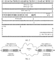
- FIG. 2 is a schematic diagram of OAM packet encapsulation in the first embodiment of a method for measuring network packet loss according to the present invention. Specifically, in order to enable an OAM packet to pass through a same path as a service data packet a route for a data packet of a service stream is searched from a sending-end network device and then two-layer encapsulation is performed on the OAM packet. Referring to FIG. 2 , encapsulation labels are an outer MPLS lsp Label and an inner MPLS vpn Label. With the two-layer encapsulation, the OAM packet has a same destination address as the data packet of the service stream.
- the OAM packet may be transmitted to a new receiving-end network device along with the data packet of the service stream according to an encapsulated new destination IP address.
- the receiving-end network device needs to distinguish the OAM packet from a normal data packet of the service stream.
- a GAL label is used to identify the OAM packet, where the GAL label is a reserved label defined in IETF MPLS. After the receiving-end network device pops both the outer and inner labels of the OAM packet, the receiving-end network device obtains the GAL label of the OAM packet.
- the receiving-end network device determines, according to the label, that the received packet is an OAM packet, and performs, according to the measurement period identifier to be queried which is included in the OAM packet, querying through OAM deployed at the receiving end, to search a second data packet count corresponding to the measurement period identifier to be queried.
- the OAM packet sent by the network device at the sending end is encapsulated by using labels, that is, an MPLS lsp Label and an MPLS vpn Label, which ensures that the OAM packet and the data packet of the service stream are transmitted on a same path. After a failover occurs on a node of the network, a path of the service stream is also switched accordingly.
- an encapsulated outer MPLS lsp Label and inner MPLS vpn Label are also updated, which ensures that the OAM packet and the service stream are subsequently transmitted on the same path. Therefore, in point-to-multipoint and multipoint-to-multipoint network scenarios, after a service link is switched, a network packet loss situation can be still measured accurately.
- the sending end is a cell site gateway (Cell Site Gateway, CSG for short)
- the receiving end is a radio network controller site gateway (Radio Network Controller Site Gateway, RSG for short)
- the method further includes:
- each service stream has particular characteristic information of the service stream, and the characteristic information of the service stream includes at least duple information in a quintuple.
- the quintuple refers to a source IP address, a destination IP address, an IP address prefix, a source protocol port number, and a destination protocol port number, in an IP header.
- information of type of service (Type of Service, TOS for short) fields in the IP header may also be added to specify the characteristic information of the service stream.
- the fields may be all specified, in this case, the measured service stream is finer; or the fields may be partially specified, for example, the source IP address and destination IP address in the quintuple are specified as the characteristic information of the service stream; or the source IP address, destination IP address, and IP address prefix are specified as the characteristic information of the service stream; or the source IP address, destination IP address, IP address prefix, and TOS information are specified as the characteristic information of the service stream.
- an upstream sending-end network device CSG After a service stream enters a network, first an upstream sending-end network device CSG needs to identify the service stream.
- the identification process is: The network device performs matching identification according to preset service stream characteristic information and the service stream characteristic information of the service stream, and if the two are matched successfully, the upstream sending-end network device CSG determines that the service stream is a target service stream.
- a transmission scenario of the service stream on the network is a point-to-multipoint or multipoint-to-multipoint network scenario, regardless of a specific path of the service stream, it may be determined, based on the service stream characteristic information of the service stream, whether data packets at each upstream sending end and downstream receiving end belong to a same service stream.
- the network device CSG adds an identifier to the data packets of the service stream according to a current measurement period identifier.
- FIG. 3 is a schematic diagram of a method for adding an identifier in the first embodiment of a method for measuring network packet loss according to the present invention.
- an identifier is added to a data packet of a service stream, that is, an identifier is periodically added, at an upstream sending-end CSG, to a reserved bit in an IP header of each data packet of the service stream.
- an identifier 1 is added to data packets in a period interval
- an identifier 0 is added to data packets in an adjacent period interval. Therefore, data packets of the service stream may be divided into different measurement intervals according to identifier attributes.
- Counters are set on the upstream sending-end network device CSG to collect statistics on counts of data packets of the service stream with different identifiers at intervals, where the number of counters is the same as the number of identifier attributes, and measurement is performed at each period interval, for example, a count of data packets at an i th interval of the upstream sending-end network device CSG is N; corresponding counters are also set on a downstream receiving-end network device RSG to separately count data packets with different identifiers, for example, a count of second data packets at an i th interval of the downstream receiving-end network device RSG is M.
- identifiers of adjacent intervals are different, even if service data packets with disordered other identifiers occur at the boundary of the adjacent intervals, the service data packets are not counted in the counter of the identifier, but are counted in counters of corresponding identifiers of the service data packets with disordered other identifiers, thereby ensuring accuracy and integrity of counting. For example, referring to FIG.
- the upstream sending-end network device CSG adds an identifier 1 to data packets in a period, and adds an identifier 0 to data packets in an adjacent period; a counter 1 is set to collect statistics on counts of the data packets to which the identifier 1 is added, and a counter 0 is set to collect statistics on counts of the data packets to which the identifier 0 is added. Corresponding counter 1 and counter 0 are also set on the downstream receiving end raw device RSG to separately count data packets with an identifier 1 and data packets with an identifier 0 in a same service stream.
- the receiving-end network device RSG feeds back a measurement packet carrying a second data packet count M to the sending-end network device CSG.
- Performing data packet counting processing on the service stream sent to the receiving end includes:
- a measurement period identifier to which the measurement interval belongs is unique. Therefore, the objective may be achieved as long as data packets in two adjacent measurement intervals are distinguished. Therefore, optionally, adjacent measurement intervals are distinguished in a manner of adding identifiers according to an odd measurement period identifier and an even measurement period identifier alternately. For example, referring to FIG. 3 , for a service stream, when the measurement period identifier is an even number, the upstream sending-end network device adds an identifier 0 to data packets in the measurement interval; and when the measurement period identifier is an odd number, the upstream sending-end network device adds an identifier 1 to data packets in the measurement interval.
- the sending-end network device CSG uses counters corresponding to different identifiers to count data packets with different identifiers. For example, after a target service stream enters the sending-end network device CSG, an identifier 0 is added to data packets in a unit measurement period, and an identifier 1 is added to data packets in an adjacent unit measurement period.
- the upstream network device is disposed with a counter 0 and a counter 1, hands over, in a unit of measurement period, the data packets with the identifier 0 to the corresponding counter 0 for counting data packets, and hands over, in a unit of measurement period, the data packets with the identifier 1 to the corresponding counter 1 for counting data packets.
- Adding an identifier to the data packets of the service stream may include:
- a range that may be specified for the identifier is total 6 bits in the two fields TOS and Flags in the IP header of the data packets, that is, the third to the seventh bits of the TOS, and the 0 th bit of flags.
- the bits of the IP header may be used to add an identifier.
- the 0 th bit of Flags is a current unique reserved bit in the IP header.
- the bit may be used to add an identifier to a data packet.
- performing data packet counting processing on the received service stream by the receiving end includes:
- the receiving-end network device RSG when the service stream reaches the downstream receiving-end network device RSG through the network, the receiving-end network device RSG also needs to identify the service stream according to the characteristic information of the service stream, to determine whether the service stream is a target service stream. This process is similar to the identification process of the upstream sending-end network device CSG, and is not repeatedly described herein.
- the receiving end counts, by using counters corresponding to different identifiers and in a unit of measurement period, data packets to which different identifiers are added.
- the sending end is an RSG
- the receiving end is a CSG
- the method further includes:
- FIG. 4 is a signaling flowchart of a second embodiment of a method for measuring network packet loss according to the present invention. The following describes, based on FIG. 4 , the first embodiment of the method for measuring network packet loss according to the present invention in detail.
- the network devices in the embodiment of the present invention may be a CSG and an RSG. It is assumed that the CSG is a sending-end network device and that the RSG is a receiving-end network device.
- the sending-end network device CSG identifies the corresponding target service stream, and adds an identifier to data packets in each measurement interval in a unit of measurement period.
- the specific identification method and technical solution have been described in detail in the first embodiment of the method for measuring network packet loss, and are not repeatedly described herein. If the service stream is a target service stream, the CSG counts the target service stream, and enables data packets with different identifiers to correspond to different counters for counting. The specific counting method and technical solution are described in detail in the first embodiment of the method for measuring network packet loss, and are not repeatedly described herein. And a first data packet count is generated.
- the target service stream after being counted is transmitted by the CSG to the RSG through the network.
- the RSG identifies the service stream according to the characteristic information of the service stream, and when the service stream is matched, collects corresponding packet loss statistics of the target service stream.
- the method and technical solution of the RSG are similar to that of the CSG, and are not repeatedly described herein.
- the OAM packet is encapsulated.
- a GAL label is added to the OAM packet. For details, reference may be made to FIG. 2 .
- the RSG feeds back, to the CSG, a corresponding data packet carrying the second data packet count.
- two-layer encapsulation is also performed on the data packet, and is transmitted after a GAL label is added.
- the sending-end CSG compares the first data packet count and second data packet count corresponding to a consistent measurement period identifier, to obtain the network packet loss situation of the measurement period identifier by calculation.
- the RSG is a sending end of the OAM packet
- the CSG is a receiving end of the OAM packet
- the principle is similar, and is not repeatedly described.
- a sending-end network device identifies a service stream according to characteristic information of the service stream, to determine whether the service stream is a target service stream, and if the service stream is a target service stream, the sending-end network device adds an identifier to data packets of the service stream according to a current measurement period identifier; and performing data packet counting processing on a service stream sent to a receiving end includes: counting, by the sending-end network device by using counters corresponding to different identifiers, data packets to which different identifiers are added. Performing packet counting statistics on data packets of the service stream is implemented according to a unit of measurement period.
- the sending end adds a GAL label to the OAM packet, and encapsulates the OAM packet according to a destination address of the service stream, and therefore, it is implemented that the OAM packet is distinguished from the data packets of the service stream at the receiving end, thereby ensuring that network packet loss measurement is performed normally.
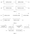
- FIG. 5 is a schematic structural diagram of a first embodiment of a network device according to the present invention.
- the network device includes a counting module 40, a statistics module 42, a sending module 44, and a receiving module 46.
- the counting module 40 is configured to perform data packet counting processing on a service stream sent to a receiving end, to obtain a first data packet count corresponding to a measurement period identifier.
- the counting module 40 sets corresponding counters for different measurement period identifiers.
- the sending module 44 is configured to send an OAM packet including a measurement period identifier to be queried to the receiving end, where the OAM packet and a data packet of the service stream are transmitted on a same path.
- the sending module 44 encapsulates the OAM packet, so that the sent OAM packet and the data packet of the service stream have a same destination IP address, thereby ensuring that the OAM packet and the data packet of the service stream are transmitted on the same path.
- the receiving module 46 is configured to receive a second data packet count that is fed back by the receiving end after the receiving end receives the OAM packet and corresponding to the measurement period identifier to be queried, where the second data packet count is a count obtained by the receiving end by performing data packet counting processing on the received service stream.
- the statistics module 42 is configured to determine a network packet loss situation according to the first data packet count and the second data packet count.
- the network device in this embodiment may be used to execute the technical solution of a method embodiment shown in FIG. 1 .
- Implementation principles and technical effects thereof are similar, and are not repeatedly described herein.
- FIG. 6 is a schematic structural diagram of a second embodiment of a network device according to the present invention. Based on the structure of the network device in FIG. 5 , the network device in the second embodiment further includes an encapsulating module 48.
- the encapsulating module 48 is configured to: before the sending module 44 sends the OAM packet including the measurement period identifier to be queried to the receiving end, add a GAL label to the OAM packet, and encapsulate the OAM packet according to a destination address of the service stream.
- the statistics module 48 encapsulates the OAM packet before the sending module 44 sends the OAM packet.
- the specific encapsulation method and technical solution have been described in the first embodiment of the method for measuring network packet loss, and are not repeatedly described herein.
- the network device in this embodiment may be used to execute the technical solution of the method embodiment shown in FIG. 1 .
- the implementation principles and technical effects thereof are similar, and are not repeatedly described herein.
- FIG. 7 is a schematic structural diagram of a third embodiment of a network device according to the present invention. Based on the structure of the network device in FIG. 5 or FIG. 6 , the network device in the third embodiment further includes an identification processing module 41.
- the identification processing module 41 is configured to identify the service stream according to characteristic information of the service stream, to determine whether the service stream is a target service stream, and if the service stream is a target service stream, add an identifier to the data packet of the service stream according to a current measurement period identifier.
- the counting module 40 is specifically configured to count, by using counters corresponding to different identifiers, data packets to which different identifiers are added.
- the device is an RSG, and the receiving end is a CSG; or the device is a CSG, and the receiving end is an RSG.
- the network device of this embodiment may be used to execute the technical solution of the method embodiment shown in FIG. 1 .
- the implementation principles and technical effects thereof are similar, and are not repeatedly described herein.
- a system for measuring network packet loss includes: a CSG and at least one RSG, where the CSG uses any network device in the first embodiment to the third embodiment of the network device in the present invention, and the RSG uses any network device in the first embodiment to the third embodiment of the network device in the present invention.
- the CSG uses any network device in the first embodiment to the third embodiment of the network device in the present invention
- the RSG uses any network device in the first embodiment to the third embodiment of the network device in the present invention.
- the system may execute the technical solution of the first embodiment of the method for measuring network packet loss according to the present invention.
- the implementation principles and technical effects of the system are similar, and are not repeatedly described herein.
- FIG. 8 is a schematic structural diagram of a second embodiment of a system for measuring network packet loss according to the present invention.
- the following describes a specific problem of the system for measuring network packet loss according to the present invention in two networks: an HoVPN (Hierarchy of VPN) and an H-VPN (Hierarchy VPN).
- HoVPN Hierarchy of VPN
- H-VPN Hierarchy VPN
- a network is a first VPN (the first VPN is a hierarchy VPN, Hierarchy-VPN, H-VPN for short) network.
- the OAM packet is forwarded through an aggregation device (Aggregation, AGG for short).
- AGG aggregation device
- the AGG only pops an outer MPLS lsp Label of OAM, and replaces the MPLS lsp Label for forwarding.
- an MPLS vpn Label is not popped, and consequently a GAL label is not exposed. Therefore, the OAM packet is directly forwarded through an AGG node. If switching occurs in an AGG1 and an AGG2, forwarding of the OAM packet is not affected.
- the OAM packet When an OAM packet is sent in a direction from the RSG to the CSG, the OAM packet is sent in a direction from a CSG to an RSG, because an AGG needs to configure a VPN instance, the VPN instance of the AGG learns a route to the RSG, and meanwhile, a default route is advertised to the CSG by using a routing policy, that is, when the CSG encapsulates the OAM packet, because a function of the CSG is limited, all OAM packets share a same MPLS VPN Label.
- a routing policy that is, when the CSG encapsulates the OAM packet, because a function of the CSG is limited, all OAM packets share a same MPLS VPN Label.
- the program may be stored in a computer readable storage medium.
- the foregoing storage medium includes: any medium that can store program code, such as a ROM, a RAM, a magnetic disk, or an optical disc.
Landscapes
- Engineering & Computer Science (AREA)
- Computer Networks & Wireless Communication (AREA)
- Signal Processing (AREA)
- Environmental & Geological Engineering (AREA)
- Health & Medical Sciences (AREA)
- Cardiology (AREA)
- General Health & Medical Sciences (AREA)
- Data Exchanges In Wide-Area Networks (AREA)
Claims (8)
- Procédé de mesure de perte de paquets de réseau, comportant les étapes consistant à :faire effectuer (S100), par une extrémité d'émission, un traitement de comptage de paquets de données sur un flux de service envoyé à une extrémité de réception, pour obtenir un premier comptage de paquets de données correspondant à un identifiant de période de mesure ;faire envoyer (S 102) à l'extrémité de réception, par l'extrémité d'émission, un paquet d'exploitation, d'administration et de maintenance, OAM, comportant un identifiant de période de mesure à interroger, le paquet d'OAM et un paquet de données du flux de service étant transmis sur un même chemin ;faire recevoir (S 104), par l'extrémité d'émission, un deuxième comptage de paquets de données qui est renvoyé par l'extrémité de réception après que l'extrémité de réception a reçu le paquet d'OAM et correspondant à l'identifiant de période de mesure à interroger, le deuxième comptage de paquets de données étant un comptage obtenu par l'extrémité de réception en effectuant un traitement de comptage de paquets de données sur le flux de service reçu ; etfaire déterminer (S 106), par l'extrémité d'émission, une situation de perte de paquets de réseau d'après le premier comptage de paquets de données et le deuxième comptage de paquets de données ;le procédé comportant en outre, avant l'envoi à l'extrémité de réception, par l'extrémité d'émission, d'un paquet d'OAM comportant un identifiant de période de mesure à interroger, les étapes consistant à :faire ajouter, par l'extrémité d'émission, une étiquette générique associée de canal, GAL, au paquet d'OAM, et encapsuler le paquet d'OAM d'après une adresse de destination du flux de service.
- Procédé selon la revendication 1, l'extrémité d'émission étant une passerelle de site de cellule, CSG, l'extrémité de réception étant une passerelle de site de contrôleur de réseau radio, RSG, et le procédé comportant en outre, avant la réalisation d'un traitement de comptage de paquets de données sur un flux de service envoyé à une extrémité de réception, les étapes consistant à :faire identifier (S401), par la CSG, le flux de service d'après des informations caractéristiques du flux de service, pour déterminer si le flux de service est un flux de service cible ; etsi le flux de service est un flux de service cible, faire ajouter (S401), par la CSG, un identifiant au paquet de données du flux de service d'après l'identifiant actuel de période de mesure ; etla réalisation (S 100) d'un traitement de comptage de paquets de données sur un flux de service envoyé à une extrémité de réception comportant l'étape consistant à :faire compter, par la CSG en utilisant des compteurs correspondant à différents identifiants, des paquets de données auxquels différents identifiants sont ajoutés.
- Procédé selon la revendication 1, l'extrémité d'émission étant une RSG, l'extrémité de réception est une passerelle de site de cellule, CSG, et le procédé comportant en outre, avant la réalisation (S 100) d'un traitement de comptage de paquets de données sur un flux de service envoyé à une extrémité de réception, les étapes consistant à :faire identifier, par la RSG, le flux de service d'après des informations caractéristiques du flux de service, pour déterminer si le flux de service est un flux de service cible ; etsi le flux de service est un flux de service cible, faire ajouter, par la RSG, un identifiant au paquet de données du flux de service d'après l'identifiant actuel de période de mesure ; etla réalisation (S 100) d'un traitement de comptage de paquets de données sur un flux de service envoyé à une extrémité de réception comportant l'étape consistant à :faire compter par la RSG, en utilisant des compteurs correspondant à différents identifiants, des paquets de données auxquels différents identifiants sont ajoutés, dans une unité de période de mesure.
- Procédé selon la revendication 2 ou 3, la réalisation (S 100), par l'extrémité d'émission, d'un traitement de comptage de paquets de données sur le flux de service reçu comportant les étapes consistant à :faire identifier, par l'extrémité d'émission, le flux de service d'après des informations caractéristiques du flux de service, pour déterminer si le flux de service est un flux de service cible ; etsi le flux de service est un flux de service cible, faire compter par l'extrémité d'émission, en utilisant des compteurs correspondant à différents identifiants, des paquets de données auxquels différents identifiants sont ajoutés, dans une unité de période de mesure.
- Dispositif de réseau, comportant un module (40) de comptage, un module (44) d'émission, un module (46) de réception, et un module (42) de statistiques :le module (40) de comptage étant configuré pour effectuer un traitement de comptage de paquets de données sur un flux de service envoyé à une extrémité de réception, pour obtenir un premier comptage de paquets de données correspondant à un identifiant de période de mesure ;le module (44) d'émission étant configuré pour envoyer à l'extrémité de réception un paquet d'exploitation, d'administration et de maintenance, OAM, comportant un identifiant de période de mesure à interroger, le paquet d'OAM et un paquet de données du flux de service étant transmis sur un même chemin ;le module (46) de réception étant configuré pour recevoir un deuxième comptage de paquets de données qui est renvoyé par l'extrémité de réception après que l'extrémité de réception a reçu le paquet d'OAM et correspondant à l'identifiant de période de mesure à interroger, le deuxième comptage de paquets de données étant un comptage obtenu par l'extrémité de réception en effectuant un traitement de comptage de paquets de données sur le flux de service reçu ; etle module (42) de statistiques étant configuré pour déterminer une situation de perte de paquets de réseau d'après le premier comptage de paquets de données et le deuxième comptage de paquets de données ;le dispositif de réseau comportant en outre :un module (48) d'encapsulation, configuré pour :avant que le module (44) d'émission envoie le paquet d'OAM comportant l'identifiant de période de mesure à interroger à l'extrémité de réception, ajouter une étiquette générique associée de canal, GAL, au paquet d'OAM, et encapsuler le paquet d'OAM d'après une adresse de destination du flux de service.
- Dispositif de réseau selon la revendication 5, comportant en outre :un module (41) de traitement d'identification, configuré pour identifier le flux de service d'après des informations caractéristiques du flux de service, pour déterminer si le flux de service est un flux de service cible, et si le flux de service est un flux de service cible, ajouter un identifiant au paquet de données du flux de service d'après l'identifiant actuel de période de mesure ;le module (40) de comptage étant spécifiquement configuré pour compter, en utilisant des compteurs correspondant à différents identifiants, des paquets de données auxquels différents identifiants sont ajoutés.
- Dispositif de réseau selon la revendication 6, le dispositif de réseau étant une passerelle de site de contrôleur de réseau radio, RSG, et l'extrémité de réception étant une passerelle de site de cellule, CSG ; ou le dispositif de réseau étant une CSG et l'extrémité de réception étant une RSG.
- Système de mesure de perte de paquets de réseau, comportant une passerelle de site de cellule, CSG, et au moins une passerelle de site de contrôleur de réseau radio, RSG, la CSG utilisant le dispositif de réseau selon l'une quelconque des revendications 5 à 7, la RSG utilisant le dispositif de réseau selon l'une quelconque des revendications 5 à 7, une passerelle parmi la CSG et la RSG servant d'extrémité d'émission, et l'autre servant d'extrémité de réception.
Applications Claiming Priority (2)
| Application Number | Priority Date | Filing Date | Title |
|---|---|---|---|
| CN201210379426.3A CN102904775B (zh) | 2012-09-29 | 2012-09-29 | 网络丢包测量方法、设备和系统 |
| PCT/CN2013/077289 WO2014048136A1 (fr) | 2012-09-29 | 2013-06-17 | Procédé, dispositif et système de mesure de perte de paquets de réseau |
Publications (3)
| Publication Number | Publication Date |
|---|---|
| EP2884697A1 EP2884697A1 (fr) | 2015-06-17 |
| EP2884697A4 EP2884697A4 (fr) | 2015-08-19 |
| EP2884697B1 true EP2884697B1 (fr) | 2018-04-11 |
Family
ID=47576823
Family Applications (1)
| Application Number | Title | Priority Date | Filing Date |
|---|---|---|---|
| EP13841309.1A Not-in-force EP2884697B1 (fr) | 2012-09-29 | 2013-06-17 | Procédé, dispositif et système de mesure de perte de paquets de réseau |
Country Status (4)
| Country | Link |
|---|---|
| US (1) | US20150195169A1 (fr) |
| EP (1) | EP2884697B1 (fr) |
| CN (1) | CN102904775B (fr) |
| WO (1) | WO2014048136A1 (fr) |
Families Citing this family (36)
| Publication number | Priority date | Publication date | Assignee | Title |
|---|---|---|---|---|
| CN103166738B (zh) * | 2011-12-19 | 2018-02-27 | 中兴通讯股份有限公司 | 一种测量双端帧丢失的装置及方法 |
| CN102904775B (zh) * | 2012-09-29 | 2015-04-29 | 华为技术有限公司 | 网络丢包测量方法、设备和系统 |
| CN103684923B (zh) * | 2013-12-24 | 2017-10-17 | 华为技术有限公司 | 一种丢包测量的方法及网络设备 |
| WO2015149353A1 (fr) | 2014-04-04 | 2015-10-08 | 华为技术有限公司 | Procédé de traitement de paquets oam, dispositif de réseau, et système de réseau |
| CN105281969B (zh) * | 2014-07-04 | 2019-11-29 | 华为技术有限公司 | 一种统计信息获取方法及装置 |
| CN104270284A (zh) * | 2014-09-19 | 2015-01-07 | 烽火通信科技股份有限公司 | 基于分布式架构中端口或lsp的业务丢包率测量方法 |
| WO2016049872A1 (fr) * | 2014-09-30 | 2016-04-07 | 华为技术有限公司 | Dispositif et procédé pour mesurer une perte de paquet de réseau |
| CN105634840B (zh) * | 2014-10-29 | 2020-05-05 | 中兴通讯股份有限公司 | 一种丢包的测量方法及装置 |
| CN105007198B (zh) * | 2015-07-23 | 2018-08-14 | 中国电子科技集团公司第四十一研究所 | 一种ip数据包乱序模拟仿真电路及方法 |
| CN114726479B (zh) * | 2017-07-18 | 2024-12-27 | 华为技术有限公司 | 一种检测块发送和接收的方法、网络设备和系统 |
| CN109714221B (zh) * | 2017-10-25 | 2022-11-01 | 阿里巴巴集团控股有限公司 | 网络数据包的确定方法、装置及系统 |
| CN110545241B (zh) * | 2018-05-28 | 2022-05-17 | 华为技术有限公司 | 一种报文处理方法和装置 |
| CN109274522B (zh) * | 2018-08-27 | 2021-12-14 | 苏州盛科通信股份有限公司 | 一种oam信息的处理方法、装置、设备及存储介质 |
| JP6856257B2 (ja) * | 2018-11-09 | 2021-04-07 | Necプラットフォームズ株式会社 | ネットワークシステム、管理サーバ及び通信解析プログラム |
| CN110191027B (zh) * | 2019-06-19 | 2022-08-16 | 上海电气泰雷兹交通自动化系统有限公司 | 一种ccu和mcu之间的通信错误诊断方法 |
| CN112398557B (zh) * | 2019-08-16 | 2022-06-28 | 华为技术有限公司 | 时延统计方法、装置、存储介质及系统 |
| CN114073049B (zh) * | 2019-09-21 | 2023-11-17 | 华为技术有限公司 | 用于可靠性测量的方法和网络节点 |
| CN112714007B (zh) * | 2019-10-24 | 2022-07-01 | 烽火通信科技股份有限公司 | 检测ioam所有设备业务报文染色标记的方法及装置 |
| CN113067740B (zh) * | 2020-01-02 | 2023-09-05 | 中国移动通信有限公司研究院 | 随路性能检测方法、装置、设备及计算机可读存储介质 |
| US11283699B2 (en) | 2020-01-17 | 2022-03-22 | Vmware, Inc. | Practical overlay network latency measurement in datacenter |
| CN113328903B (zh) * | 2020-02-29 | 2023-02-03 | 华为技术有限公司 | 检测传输质量的方法、装置和系统 |
| CN113676364B (zh) * | 2020-05-13 | 2022-10-18 | 烽火通信科技股份有限公司 | 基于ioam报文封装的网络设备智能运维方法及系统 |
| CN111786859A (zh) * | 2020-07-17 | 2020-10-16 | 中国联合网络通信集团有限公司 | 丢包检测方法、装置及存储介质 |
| US11570090B2 (en) | 2020-07-29 | 2023-01-31 | Vmware, Inc. | Flow tracing operation in container cluster |
| CN112039724B (zh) * | 2020-08-17 | 2021-09-28 | 鹏城实验室 | 网络丢包检测方法、装置、存储介质及网络系统 |
| CN112737874B (zh) * | 2020-12-23 | 2022-08-30 | 新华三技术有限公司 | 报文的丢包统计实现方法及装置 |
| US11736436B2 (en) | 2020-12-31 | 2023-08-22 | Vmware, Inc. | Identifying routes with indirect addressing in a datacenter |
| US11336533B1 (en) | 2021-01-08 | 2022-05-17 | Vmware, Inc. | Network visualization of correlations between logical elements and associated physical elements |
| US11687210B2 (en) | 2021-07-05 | 2023-06-27 | Vmware, Inc. | Criteria-based expansion of group nodes in a network topology visualization |
| US11711278B2 (en) | 2021-07-24 | 2023-07-25 | Vmware, Inc. | Visualization of flow trace operation across multiple sites |
| US11677645B2 (en) * | 2021-09-17 | 2023-06-13 | Vmware, Inc. | Traffic monitoring |
| CN114079622B (zh) * | 2021-10-22 | 2023-05-12 | 深信服科技股份有限公司 | 丢包网口确定方法、装置及存储介质 |
| CN114025354A (zh) * | 2021-11-17 | 2022-02-08 | 圆藏(上海)科技有限公司 | 一种降低信息传输误码的通信方法、系统及存储介质 |
| CN114157586A (zh) * | 2021-12-15 | 2022-03-08 | 苏州盛科通信股份有限公司 | 一种提升twamp检测准确性的方法、装置及存储装置 |
| CN114666243A (zh) * | 2022-03-29 | 2022-06-24 | 迈普通信技术股份有限公司 | 网络质量测量方法、装置、系统、电子设备及存储介质 |
| CN116346577B (zh) * | 2023-02-28 | 2025-11-28 | 深圳华为云计算技术有限公司 | 基于云平台的网络运维方法、系统和计算设备集群 |
Family Cites Families (11)
| Publication number | Priority date | Publication date | Assignee | Title |
|---|---|---|---|---|
| CN1881908A (zh) * | 2005-06-13 | 2006-12-20 | 华为技术有限公司 | 测量mpls网络性能参数的方法 |
| WO2007056915A1 (fr) * | 2005-11-17 | 2007-05-24 | Huawei Technologies Co., Ltd. | Procede pour mesurer un parametre concernant les performances d'un reseau mpls, et dispositif et systeme pour envoyer un paquet |
| JP2008085906A (ja) * | 2006-09-28 | 2008-04-10 | Fujitsu Ltd | パケット損失率算出システム |
| CN101729197B (zh) * | 2008-10-14 | 2014-04-16 | 华为技术有限公司 | 一种丢包率检测方法、装置及系统 |
| CN101605020A (zh) * | 2009-07-07 | 2009-12-16 | 中兴通讯股份有限公司 | 一种丢包率检测方法、系统及装置 |
| CN102055598A (zh) * | 2009-11-11 | 2011-05-11 | 中兴通讯股份有限公司 | 一种实现点到多点802.3ah协议OAM的方法及系统 |
| CN101707509A (zh) * | 2009-11-19 | 2010-05-12 | 中兴通讯股份有限公司 | 使用oam检测丢包率的方法、系统及装置 |
| EP2636243B1 (fr) * | 2010-11-05 | 2015-04-15 | Interdigital Patent Holdings, Inc. | Procédé pour effectuer des mesures de l'utilisation radio pour l'opération des liaisons radioélectriques |
| CN102185780B (zh) * | 2011-05-12 | 2015-09-16 | 中兴通讯股份有限公司 | Oam报文处理方法及装置 |
| WO2013092634A1 (fr) * | 2011-12-20 | 2013-06-27 | Thomson Licensing | Procédés de surveillance de trafic de données dans un dispositif passerelle |
| CN102904775B (zh) * | 2012-09-29 | 2015-04-29 | 华为技术有限公司 | 网络丢包测量方法、设备和系统 |
-
2012
- 2012-09-29 CN CN201210379426.3A patent/CN102904775B/zh not_active Expired - Fee Related
-
2013
- 2013-06-17 WO PCT/CN2013/077289 patent/WO2014048136A1/fr not_active Ceased
- 2013-06-17 EP EP13841309.1A patent/EP2884697B1/fr not_active Not-in-force
-
2015
- 2015-03-24 US US14/667,123 patent/US20150195169A1/en not_active Abandoned
Non-Patent Citations (1)
| Title |
|---|
| None * |
Also Published As
| Publication number | Publication date |
|---|---|
| US20150195169A1 (en) | 2015-07-09 |
| WO2014048136A1 (fr) | 2014-04-03 |
| CN102904775A (zh) | 2013-01-30 |
| CN102904775B (zh) | 2015-04-29 |
| EP2884697A4 (fr) | 2015-08-19 |
| EP2884697A1 (fr) | 2015-06-17 |
Similar Documents
| Publication | Publication Date | Title |
|---|---|---|
| EP2884697A1 (fr) | Procédé, dispositif et système de mesure de perte de paquets de réseau | |
| US11133998B2 (en) | Method, apparatus, and system for measuring network delay | |
| US9985856B2 (en) | Method, apparatus and system for measuring network packet loss | |
| CN112398557B (zh) | 时延统计方法、装置、存储介质及系统 | |
| US9450846B1 (en) | System and method for tracking packets in a network environment | |
| EP4109959A1 (fr) | Procédé et dispositif de test de flux in situ | |
| KR101443237B1 (ko) | 통신 네트워크에서의 데이터 흐름에 대한 측정 | |
| US9584396B2 (en) | Label-based measurement method, apparatus, and system | |
| JP2022532656A (ja) | パケット測定方法、デバイス、およびシステム | |
| JP6740371B2 (ja) | 複数地点パケットフローに関する性能測定 | |
| US12088489B2 (en) | Performance measurement in a packet-switched communication network | |
| EP2737666B1 (fr) | Mesure de trafic de données dans un réseau de communication | |
| EP3913862B1 (fr) | Procédé, appareil et système de détection de trafic | |
| US11121938B2 (en) | Performance measurement in a packet-switched communication network | |
| US20250392528A1 (en) | Performance measurement on live traffic transmitted through a packet-switched communication network |
Legal Events
| Date | Code | Title | Description |
|---|---|---|---|
| PUAI | Public reference made under article 153(3) epc to a published international application that has entered the european phase |
Free format text: ORIGINAL CODE: 0009012 |
|
| 17P | Request for examination filed |
Effective date: 20150310 |
|
| AK | Designated contracting states |
Kind code of ref document: A1 Designated state(s): AL AT BE BG CH CY CZ DE DK EE ES FI FR GB GR HR HU IE IS IT LI LT LU LV MC MK MT NL NO PL PT RO RS SE SI SK SM TR |
|
| AX | Request for extension of the european patent |
Extension state: BA ME |
|
| RA4 | Supplementary search report drawn up and despatched (corrected) |
Effective date: 20150716 |
|
| RIC1 | Information provided on ipc code assigned before grant |
Ipc: H04L 12/26 20060101AFI20150710BHEP |
|
| DAX | Request for extension of the european patent (deleted) | ||
| 17Q | First examination report despatched |
Effective date: 20170215 |
|
| GRAP | Despatch of communication of intention to grant a patent |
Free format text: ORIGINAL CODE: EPIDOSNIGR1 |
|
| INTG | Intention to grant announced |
Effective date: 20171020 |
|
| GRAS | Grant fee paid |
Free format text: ORIGINAL CODE: EPIDOSNIGR3 |
|
| GRAA | (expected) grant |
Free format text: ORIGINAL CODE: 0009210 |
|
| RIN1 | Information on inventor provided before grant (corrected) |
Inventor name: LIU, YANJUN Inventor name: WANG, ZULIANG Inventor name: LIU, HONGMING |
|
| AK | Designated contracting states |
Kind code of ref document: B1 Designated state(s): AL AT BE BG CH CY CZ DE DK EE ES FI FR GB GR HR HU IE IS IT LI LT LU LV MC MK MT NL NO PL PT RO RS SE SI SK SM TR |
|
| REG | Reference to a national code |
Ref country code: GB Ref legal event code: FG4D |
|
| REG | Reference to a national code |
Ref country code: CH Ref legal event code: EP |
|
| REG | Reference to a national code |
Ref country code: AT Ref legal event code: REF Ref document number: 989124 Country of ref document: AT Kind code of ref document: T Effective date: 20180415 |
|
| REG | Reference to a national code |
Ref country code: IE Ref legal event code: FG4D |
|
| REG | Reference to a national code |
Ref country code: DE Ref legal event code: R096 Ref document number: 602013035883 Country of ref document: DE |
|
| REG | Reference to a national code |
Ref country code: NL Ref legal event code: MP Effective date: 20180411 |
|
| REG | Reference to a national code |
Ref country code: LT Ref legal event code: MG4D |
|
| PG25 | Lapsed in a contracting state [announced via postgrant information from national office to epo] |
Ref country code: NL Free format text: LAPSE BECAUSE OF FAILURE TO SUBMIT A TRANSLATION OF THE DESCRIPTION OR TO PAY THE FEE WITHIN THE PRESCRIBED TIME-LIMIT Effective date: 20180411 |
|
| PG25 | Lapsed in a contracting state [announced via postgrant information from national office to epo] |
Ref country code: BG Free format text: LAPSE BECAUSE OF FAILURE TO SUBMIT A TRANSLATION OF THE DESCRIPTION OR TO PAY THE FEE WITHIN THE PRESCRIBED TIME-LIMIT Effective date: 20180711 Ref country code: AL Free format text: LAPSE BECAUSE OF FAILURE TO SUBMIT A TRANSLATION OF THE DESCRIPTION OR TO PAY THE FEE WITHIN THE PRESCRIBED TIME-LIMIT Effective date: 20180411 Ref country code: NO Free format text: LAPSE BECAUSE OF FAILURE TO SUBMIT A TRANSLATION OF THE DESCRIPTION OR TO PAY THE FEE WITHIN THE PRESCRIBED TIME-LIMIT Effective date: 20180711 Ref country code: FI Free format text: LAPSE BECAUSE OF FAILURE TO SUBMIT A TRANSLATION OF THE DESCRIPTION OR TO PAY THE FEE WITHIN THE PRESCRIBED TIME-LIMIT Effective date: 20180411 Ref country code: SE Free format text: LAPSE BECAUSE OF FAILURE TO SUBMIT A TRANSLATION OF THE DESCRIPTION OR TO PAY THE FEE WITHIN THE PRESCRIBED TIME-LIMIT Effective date: 20180411 Ref country code: PL Free format text: LAPSE BECAUSE OF FAILURE TO SUBMIT A TRANSLATION OF THE DESCRIPTION OR TO PAY THE FEE WITHIN THE PRESCRIBED TIME-LIMIT Effective date: 20180411 Ref country code: ES Free format text: LAPSE BECAUSE OF FAILURE TO SUBMIT A TRANSLATION OF THE DESCRIPTION OR TO PAY THE FEE WITHIN THE PRESCRIBED TIME-LIMIT Effective date: 20180411 Ref country code: LT Free format text: LAPSE BECAUSE OF FAILURE TO SUBMIT A TRANSLATION OF THE DESCRIPTION OR TO PAY THE FEE WITHIN THE PRESCRIBED TIME-LIMIT Effective date: 20180411 |
|
| PG25 | Lapsed in a contracting state [announced via postgrant information from national office to epo] |
Ref country code: RS Free format text: LAPSE BECAUSE OF FAILURE TO SUBMIT A TRANSLATION OF THE DESCRIPTION OR TO PAY THE FEE WITHIN THE PRESCRIBED TIME-LIMIT Effective date: 20180411 Ref country code: LV Free format text: LAPSE BECAUSE OF FAILURE TO SUBMIT A TRANSLATION OF THE DESCRIPTION OR TO PAY THE FEE WITHIN THE PRESCRIBED TIME-LIMIT Effective date: 20180411 Ref country code: HR Free format text: LAPSE BECAUSE OF FAILURE TO SUBMIT A TRANSLATION OF THE DESCRIPTION OR TO PAY THE FEE WITHIN THE PRESCRIBED TIME-LIMIT Effective date: 20180411 Ref country code: GR Free format text: LAPSE BECAUSE OF FAILURE TO SUBMIT A TRANSLATION OF THE DESCRIPTION OR TO PAY THE FEE WITHIN THE PRESCRIBED TIME-LIMIT Effective date: 20180712 |
|
| REG | Reference to a national code |
Ref country code: AT Ref legal event code: MK05 Ref document number: 989124 Country of ref document: AT Kind code of ref document: T Effective date: 20180411 |
|
| PG25 | Lapsed in a contracting state [announced via postgrant information from national office to epo] |
Ref country code: PT Free format text: LAPSE BECAUSE OF FAILURE TO SUBMIT A TRANSLATION OF THE DESCRIPTION OR TO PAY THE FEE WITHIN THE PRESCRIBED TIME-LIMIT Effective date: 20180813 |
|
| REG | Reference to a national code |
Ref country code: DE Ref legal event code: R119 Ref document number: 602013035883 Country of ref document: DE |
|
| PG25 | Lapsed in a contracting state [announced via postgrant information from national office to epo] |
Ref country code: CZ Free format text: LAPSE BECAUSE OF FAILURE TO SUBMIT A TRANSLATION OF THE DESCRIPTION OR TO PAY THE FEE WITHIN THE PRESCRIBED TIME-LIMIT Effective date: 20180411 Ref country code: DK Free format text: LAPSE BECAUSE OF FAILURE TO SUBMIT A TRANSLATION OF THE DESCRIPTION OR TO PAY THE FEE WITHIN THE PRESCRIBED TIME-LIMIT Effective date: 20180411 Ref country code: AT Free format text: LAPSE BECAUSE OF FAILURE TO SUBMIT A TRANSLATION OF THE DESCRIPTION OR TO PAY THE FEE WITHIN THE PRESCRIBED TIME-LIMIT Effective date: 20180411 Ref country code: RO Free format text: LAPSE BECAUSE OF FAILURE TO SUBMIT A TRANSLATION OF THE DESCRIPTION OR TO PAY THE FEE WITHIN THE PRESCRIBED TIME-LIMIT Effective date: 20180411 Ref country code: EE Free format text: LAPSE BECAUSE OF FAILURE TO SUBMIT A TRANSLATION OF THE DESCRIPTION OR TO PAY THE FEE WITHIN THE PRESCRIBED TIME-LIMIT Effective date: 20180411 Ref country code: SK Free format text: LAPSE BECAUSE OF FAILURE TO SUBMIT A TRANSLATION OF THE DESCRIPTION OR TO PAY THE FEE WITHIN THE PRESCRIBED TIME-LIMIT Effective date: 20180411 |
|
| REG | Reference to a national code |
Ref country code: CH Ref legal event code: PL |
|
| PLBE | No opposition filed within time limit |
Free format text: ORIGINAL CODE: 0009261 |
|
| STAA | Information on the status of an ep patent application or granted ep patent |
Free format text: STATUS: NO OPPOSITION FILED WITHIN TIME LIMIT |
|
| PG25 | Lapsed in a contracting state [announced via postgrant information from national office to epo] |
Ref country code: SM Free format text: LAPSE BECAUSE OF FAILURE TO SUBMIT A TRANSLATION OF THE DESCRIPTION OR TO PAY THE FEE WITHIN THE PRESCRIBED TIME-LIMIT Effective date: 20180411 Ref country code: IT Free format text: LAPSE BECAUSE OF FAILURE TO SUBMIT A TRANSLATION OF THE DESCRIPTION OR TO PAY THE FEE WITHIN THE PRESCRIBED TIME-LIMIT Effective date: 20180411 |
|
| REG | Reference to a national code |
Ref country code: BE Ref legal event code: MM Effective date: 20180630 |
|
| 26N | No opposition filed |
Effective date: 20190114 |
|
| REG | Reference to a national code |
Ref country code: IE Ref legal event code: MM4A |
|
| PG25 | Lapsed in a contracting state [announced via postgrant information from national office to epo] |
Ref country code: LU Free format text: LAPSE BECAUSE OF NON-PAYMENT OF DUE FEES Effective date: 20180617 Ref country code: MC Free format text: LAPSE BECAUSE OF FAILURE TO SUBMIT A TRANSLATION OF THE DESCRIPTION OR TO PAY THE FEE WITHIN THE PRESCRIBED TIME-LIMIT Effective date: 20180411 |
|
| PG25 | Lapsed in a contracting state [announced via postgrant information from national office to epo] |
Ref country code: IE Free format text: LAPSE BECAUSE OF NON-PAYMENT OF DUE FEES Effective date: 20180617 Ref country code: CH Free format text: LAPSE BECAUSE OF NON-PAYMENT OF DUE FEES Effective date: 20180630 Ref country code: FR Free format text: LAPSE BECAUSE OF NON-PAYMENT OF DUE FEES Effective date: 20180630 Ref country code: LI Free format text: LAPSE BECAUSE OF NON-PAYMENT OF DUE FEES Effective date: 20180630 Ref country code: DE Free format text: LAPSE BECAUSE OF NON-PAYMENT OF DUE FEES Effective date: 20190101 |
|
| PG25 | Lapsed in a contracting state [announced via postgrant information from national office to epo] |
Ref country code: SI Free format text: LAPSE BECAUSE OF FAILURE TO SUBMIT A TRANSLATION OF THE DESCRIPTION OR TO PAY THE FEE WITHIN THE PRESCRIBED TIME-LIMIT Effective date: 20180411 Ref country code: BE Free format text: LAPSE BECAUSE OF NON-PAYMENT OF DUE FEES Effective date: 20180630 |
|
| PG25 | Lapsed in a contracting state [announced via postgrant information from national office to epo] |
Ref country code: MT Free format text: LAPSE BECAUSE OF NON-PAYMENT OF DUE FEES Effective date: 20180617 |
|
| PG25 | Lapsed in a contracting state [announced via postgrant information from national office to epo] |
Ref country code: TR Free format text: LAPSE BECAUSE OF FAILURE TO SUBMIT A TRANSLATION OF THE DESCRIPTION OR TO PAY THE FEE WITHIN THE PRESCRIBED TIME-LIMIT Effective date: 20180411 |
|
| PG25 | Lapsed in a contracting state [announced via postgrant information from national office to epo] |
Ref country code: MK Free format text: LAPSE BECAUSE OF NON-PAYMENT OF DUE FEES Effective date: 20180411 Ref country code: HU Free format text: LAPSE BECAUSE OF FAILURE TO SUBMIT A TRANSLATION OF THE DESCRIPTION OR TO PAY THE FEE WITHIN THE PRESCRIBED TIME-LIMIT; INVALID AB INITIO Effective date: 20130617 Ref country code: CY Free format text: LAPSE BECAUSE OF FAILURE TO SUBMIT A TRANSLATION OF THE DESCRIPTION OR TO PAY THE FEE WITHIN THE PRESCRIBED TIME-LIMIT Effective date: 20180411 |
|
| PG25 | Lapsed in a contracting state [announced via postgrant information from national office to epo] |
Ref country code: IS Free format text: LAPSE BECAUSE OF FAILURE TO SUBMIT A TRANSLATION OF THE DESCRIPTION OR TO PAY THE FEE WITHIN THE PRESCRIBED TIME-LIMIT Effective date: 20180811 |
|
| PGFP | Annual fee paid to national office [announced via postgrant information from national office to epo] |
Ref country code: GB Payment date: 20230504 Year of fee payment: 11 |
|
| GBPC | Gb: european patent ceased through non-payment of renewal fee |
Effective date: 20240617 |
|
| PG25 | Lapsed in a contracting state [announced via postgrant information from national office to epo] |
Ref country code: GB Free format text: LAPSE BECAUSE OF NON-PAYMENT OF DUE FEES Effective date: 20240617 |