EP2885201B1 - Schiffsbergungssytem und -verfahren - Google Patents
Schiffsbergungssytem und -verfahren Download PDFInfo
- Publication number
- EP2885201B1 EP2885201B1 EP13748328.5A EP13748328A EP2885201B1 EP 2885201 B1 EP2885201 B1 EP 2885201B1 EP 13748328 A EP13748328 A EP 13748328A EP 2885201 B1 EP2885201 B1 EP 2885201B1
- Authority
- EP
- European Patent Office
- Prior art keywords
- vessel
- pontoon
- suction
- pontoons
- cradle
- Prior art date
- Legal status (The legal status is an assumption and is not a legal conclusion. Google has not performed a legal analysis and makes no representation as to the accuracy of the status listed.)
- Active
Links
Images


Classifications
-
- B—PERFORMING OPERATIONS; TRANSPORTING
- B63—SHIPS OR OTHER WATERBORNE VESSELS; RELATED EQUIPMENT
- B63B—SHIPS OR OTHER WATERBORNE VESSELS; EQUIPMENT FOR SHIPPING
- B63B17/00—Vessels parts, details, or accessories, not otherwise provided for
- B63B17/0018—Arrangements or devices specially adapted for facilitating access to underwater elements, e.g. to propellers ; Externally attached cofferdams or the like
Definitions
- the present invention relates to the field of salvage of vessels. More specifically the invention relates to an improved method for salvage and equipment for performing the improved method
- Salvage operations directed to shipwrecks are complex operations requiring heavy lifting equipment.
- the par buckling method is commonly used. Salvage method depends on the size of the shipwreck, the water depth, the position of the shipwreck, and requirements set by the owners, insurance company, authorities etc. Normally, a combination of tugs, large barge cranes and the like are used in such operations.
- a shipwreck has normally has to be both lifted up from the bottom and turned into an upright position, before being transported to a destination for repair or for scrapping. Normally the shipwreck also has to be stabilized by means of pontoons or to be placed onto a floating dock to allow for transport.
- the strength of a ship is, however, calculated for normal operation and not for salvage operations. Additionally, damages to the vessel resulting in the vessel going under and hitting the sea bed, and the break down resulting from corrosion after sinking, has often resulted in substantial reduction of the original strength of the vessel. Accordingly, the vessel to be salvaged may be further damaged and even disintegrate as a result of a salvage operation. Accordingly, the vessel to be salvaged has to be strengthened or the force exerted to the vessel has to be distributed over a larger part of the vessel to avoid disintegration.
- One object according to the present invention is therefore to provide a method and system for salvaging a vessel making it possible to substantially reduce the forces exerted onto limited areas of the vessel to avoid further damage and possible disintegration.
- Another object is to provide a method and a system to perform a salvage operation with no or minimal impact onshore and to the sea bed, to create no or only a small environmental impact by the salvage operation.
- the present invention provides a method for salvage of a partly or fully sunken vessel, the method comprising:
- a temporary connection between one or more pontoon(s) is provided by means of suction pads.
- suction pads provides a secure connection between the pontoon and the vessel.
- the forces needed for the relocation may be distributed over one or more areas of suction pad(s) to avoid disintegration and collapsing of the vessel to be salvaged.
- friction pads are arranged on the pontoon so that the pontoon is forced against the surface of the vessel by the suction force created by the suction pads.
- Friction pads are arranged to create friction parallel to the surface of the hull of the vessel to avoid or substantially reduce relative movement between the pontoon and the hull and thus stabilize the pontoon relative to the vessel even further than what is obtainable by means of the suction forces only.
- the method further comprises the step of securely fastening the one or more of the pontoon(s) to said surface of the vessel.
- the securely fastening is done by welding the pontoon(s) to the vessel. Welding is the presently preferred method for securely fasting of the pontoon(s) to the vessel.
- the step of securely fastening is performed between step b) and c).
- at relatively shallow water depths and if the vessel to be salvaged is lying in a position allowing it, at least a part of the securely fastening, such as welding, may be performed before the vessel is relocated.
- the step of securely fastening is performed after step c). If the vessel is located at deep waters or if the position of the vessel does not allow the secure fastening of the vessel to the pontoons to be performed before relocation, the vessel and the pontoons may be relocated, such as up-righting or lifting of the vessel and pontoons before the secure fastening is performed.
- a habitat is arranged in a space defined between the pontoon and said surface of the vessel for allowing for dry access to said space. Dry access to a space defied between the vessel and the pontoon allows for access to perform the secure fastening of the pontoon to the vessel by means of e.g. welding.
- the habitat is fastened to the pontoon(s) and are locked to the unit to be salvaged by seals loaded by forces from the suction pads.
- the pontoons after being connected to the vessel, may be trimmed by substituting water in the pontoons with air to relocate the vessel.
- one or more of the pontoon(s) is (are) connected to a barge and that the forces exerted for relocation of the vessel are generated by adjusting the trim of the barge.
- one or more of the pontoon(s) is (are) connected to lifting cables for relocation of the vessel.
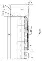
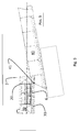
- FIG 1 is a perspective view of a vessel 1 in a cradle dock 2 comprising a plurality of buoyancy tanks or pontoons according to the present invention, after the vessel has been up-righted and lifted.
- the buoyancy tanks or pontoons may be separate tanks or pontoons.
- the tanks or pontoons may have their own piping system or they may be connected to a piping system for controlling the buoyancy of the tanks by controlling the water level therein.
- the buoyancy is controlled by a computerized control system for controlling the flow of water into and out of the tanks or pontoons, and for substitution of water with air for buoyancy.
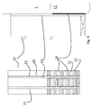
- FIG. 2 is a cross section through one embodiment according to the invention, an embodiment where the two or more buoyancy tanks or pontoons 5, 6 are connected into a first part 3 of the cradle dock 2.
- the first part 3 of the cradle dock 2 comprises a side pontoon 5 and a bottom pontoon 6.
- the bottom and side pontoons comprise tanks.
- each side pontoon 5, or bottom pontoon 6 may comprise one or more tank(s). Water may be introduced or drained from the tanks and be substituted by air according to the need by means of not shown pumps, valves and pipes.
- Such pumps and valves are parts of the above mentioned system for controlling the buoyancy of the pontoon(s), and accordingly, the pumps and valves may be manually or automatically controlled.
- the water level of each tank may be adjusted individually to control both the buoyancy volume and the centre of buoyancy and thus control both the buoyancy as such as the position of the pontoon.
- the first part 3 of the cradle dock 2 comprising the side pontoon 5 and bottom pontoon 6, is L-shaped to be arranged along one of the sides, and the bottom of a vessel to be salvaged.
- Suction pads 10 are provided at the bottom pontoon 6 and/ or at the side wall of the side pontoon 5 designed to face the bottom and side, respectively, of the vessel to be salvaged.
- Presently preferred suction pads 10 are of the type described in US 6,901,977 and US 6,701,981 , and are used in connection with an offshore loading system sold under the trademark HiLoad® Attachment System, by Remora ASA, Norway.
- FIGS 2 , 3 , 4 illustrates exemplary arrangements of the suction pads 10.
- Figures 5 and 6 illustrates cross sections through two different configurations of suction pads and habitats 20 for getting access for safely connection, such as welding, between the pontoon(s) and vessel.
- the suction pad(s) 10 comprise friction fenders 11, designed to rest against a surface such as a broad side and/or the bottom of a ship / shipwreck.
- Sealing elements such as suction pad gaskets 12, designed to create a substantially water tight seal, are surround the friction fenders 11 to create an enclosed suction chamber.
- Lipseals 13 are preferably arranged to create an addition seal as an additional barrier against the surrounding sea.
- suction pads may be arranged at any surface of the pontoons 5, 6 which are designed to rest against a submerged surface of the vessel to be salvaged.
- the suction pad After the suction pad has been arranged at a surface with a force sufficient for the sealing elements, such as suction pad gasket 12 and the lipseals 13, to create a substantially watertight seal around the friction fenders 11, water is pumped out from the chamber formed by the sealing elements, such as suction pad gasket 12 and lipseal 13, to create a negative pressure inside of the so formed chamber relative to the ambient pressure at the water depth in question.
- the friction fenders 11 are arranged so that the friction fenders are forced towards the flat surface when the suction pads 10 are forced against the surface of the vessel, or activated.
- the surface of the friction fenders 11 prevents sliding of the suction pads along the flat surface when exposed to shear forces, or sideways forces directed in parallel with the surface at which they rest. If no, or very low sideways forces are expected for a certain application, the area of friction fenders 11 may be reduced or even be omitted.
- the negative pressure inside the suction pad(s) relative to the ambient pressure increases the force with which the suction pads 10, and the thus friction fenders 11, are forced against the surface towards which it is forced. Any initial force used to create the connection between the suction pads 10 and the surface may be released as soon as the suction force is sufficiently high.
- suction pads are then forced towards the surface with a power dependent on the difference between the pressure inside of the suction pad and the surrounding pressure.
- a pressure difference of 1 atmosphere will result in a force of 10.000 kg/m 2 .
- the total suction force obtainable is thus dependent on both the pressure difference over the suction pad and the total area of suction pad(s).
- the water inside the suction pad is preferably substituted with a gas, such as air. If practical in a given situation or at a given water depth, the inside of the suction pads is vented to the atmosphere to allow the pressure difference given by water depth and the atmospheric pressure at the surface to provide the pressure difference creating the suction forces.
- the force obtainable may be increased by reducing the internal gas pressure inside the suction pad below 1 bar, such as 0.5 bar.
- the use of vacuum, such as a pressure of 0.5 bar may give sufficient force between the suction pad and the surface at which it rests, even in shallow waters, or even at the surface.
- Rigid or flexible piping / tubing may be used to connect the inner of the suction pads to the surface air, to lead air for substitution of the water that is pumped out of the suction pads.
- pumps and or air tanks may be provided to keep the air pressure inside of the suction pad at the required pressure. The skilled person will, however, understand which alternatives in obtaining a reduced pressure inside of the suction pads that is available in a given situation.
- two or more suction pads are preferably arranged to give a suction surface divided between two or more suction pads. Two or more suction pads will give a higher degree of control of the forces. If a leakage appears for one suction pad (e.g. due to an uneven surface, perforations in the surface etc, such a leakage will not be damaging for an operation as the other suction pad(s) will be intact.
- a habitat 20 may be arranged at the pontoon(s) such as at the first part 3 of the cradle dock 2.
- the habitat 20 comprises a channel 21 made in a pontoon as illustrated in figures 4 , 5 , 6 .
- Sealing elements are provided to stop or substantially reduce the water ingress from the surrounding water into the habitat.
- Figures 5 and 6 illustrate to different arrangements of sealing elements for the habitat 20 and a neighbouring suction pad 10. The two arrangements have in common that there is provided sealing elements both around the suction pad 20 and the habitat 20.
- Figure 5 illustrates a first embodiment where both a suction pad gasket 12 and a lipseal 13 are arranged as a part of the suction pad only, whereas a habitat seal gasket 12' and lipseal 13' are arranged around the edges of the habitat 20, to define a watertight chamber surrounding the channel 21.
- the gasket 12' , lipseal 13 and the channel 21 are arranged so that when the suction tabs(s) 10 of the pontoon in question is(are) resting at a surface and the suction tabs are activated to give suction power to keep the pontoon fastened to the surface, the gasket 12' and the lipseal 13' are also being forced towards the surface to form a watertight connection.
- the water in the habitat may then be substituted with air at e.g. the same pressure as inside of the suction tabs, i.e. preferably atmospheric pressure.
- air e.g. the same pressure as inside of the suction tabs, i.e. preferably atmospheric pressure.
- the suction force of the area of the habitat will also add to the suction force of the suction pads and increase the total suction power between the pontoon and the vessel to be salvaged provided that the ambient pressure at the depth in question is at 1 bar or higher.
- a continuous gasket 22 may be provided along all rims of channel 21 to define a habitat.
- one gasket 22 may be provided to define a watertight chamber 24 between the flat surface of the vessel and the pontoon, in which watertight chamber 24 one or more channel(s) is(are) provided to give access for personnel to the vessel and the pontoon.
- watertight chamber 24 one or more channel(s) is(are) provided to give access for personnel to the vessel and the pontoon.
- the skilled person will understand how to pump water out of the habitat and to substitute the water with air at atmospheric pressure, even though the control system, pumps, and valves are not illustrated of further described.
- the pressure inside the habitat(s) and the suction pad(s) may not be the same.
- the pressure inside the habitats is substantially atmospheric pressure, whereas the pressure inside the suction pads may differ dependent on the required suction power, water depth etc.
- the embodiment illustrated in figure 6 is a less complex embodiment then the one illustrated in figure 5 .
- the basis principle is, however, the same.
- the habitat 20 of figure 6 is at least partly integrated with a suction pad 10, as the gasket 12' is only provided at one side of the channel 21 as the lipseal 13 and gasket 12 for the neighbouring suction pad is used to provide a water seal at the other side of the channel 21.
- the gasket 12' may be omitted if suction pads are arranged continuously along the rims of the channel 21 to make a watertight connection at at both side and the lower end of the channel 21.
- the habitat 20 is a separate construction that is designed to be arranged to get access for personnel and equipment to the pontoon and hull of the vessel.
- the habitat is constructed in a solid or partly resilient material being open towards the vessel to be salvaged to enable personnel and/or equipment for performing operations and / or control, to access the compartment defined by the vessel and the walls of the habitat.
- One or more gasket(s) 12' is (are) arranged to provide a watertight seal to give a watertight chamber 24 around one or more habitat(s) as described above.
- access channels are necessary for personnel to get access to the habitats from the surface.
- the channel 21 may be continued to above sea level to provide access to the habitat.
- access channels may be provided either via a channel 21 in a pontoon that is partly above sea level or via specially provided channels.
- access to habitats on totally submerged pontoons may also be provided via submarines, diving bells, or the like.
- the cradle dock 2 also comprises a second part 30 designed to be connected to the opposite broad side to where the first part is arranged, and/or to the bottom of the vessel 1.
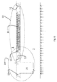
- Figure 3 illustrates a length section A-A in figure 2 , through a cradle dock 2 parallel to the bottom of the vessel. The position of the vessel to be salvaged is indicated by the reference sign 1.
- Suction pads 10 are arranged on the first part 2, comprising a side pontoon 5 and a bottom pontoon 6.
- a gasket 22 defines a watertight chamber 24, where one of more habitats 20 may be provided.
- Figure 4 illustrate different views of an exemplary second part 30 and illustrates the suction pads 10 arranged thereon, and two channels 21 arranged in the second part 30, to provide for two habitats 20.
- the cleaning of the relevant parts of the wreck may be performed by means of any suitable equipment for the cleaning of a vessel.
- the choice of cleaning solution will depend on different variables, such as the depth, the degree of fouling and sedimentation etc.
- the method may comprise the use of remotely operated equipment, such as e.g. an ROV, or the use of divers, or other known solutions.
- the first and second part of the cradle dock 2 may differ dependent on the situation. If the wreck is tilted so that it makes it possible to get easy access to one of the broad sides, and parts of the bottom of the vessel, the first part 3 of the cradle dock 2 has a L-shaped cross section as illustrated in the figures. The first part 3 is then arranged onto the vessel to be salvaged so that the side pontoon 5 is resting on the broad side of the vessel and the bottom pontoon 6 is resting on the bottom of the vessel. The suction pads at the bottom pontoon 6 and / or the side pontoon 5 is then activated by lowering the internal pressure of the suction pads.
- the first part of the cradle dock may be divided in two or more parts in the longitudinal direction of the vessel.
- a reason to divide the first part longitudinally is that it is easier to position a shorter part than one long enough to serve as a half floating dock for a vessel. Additionally, obstacles may hinder arranging the first part at parts of the wreck. By dividing the first part in two or more shorter parts, such obstacles may be avoided.
- the parts, or the side pontoon and / or the bottom pontoon may be fully or partly filled with water as required for the operation.
- the wreck and the first part(s) of the cradle dock may be repositioned to allow access to the part of the shipwreck that were inaccessible before the start of the operation.
- the repositioning may comprise substituting the water in the pontoons with air to create buoyancy to facilitate the repositioning.
- lifting equipment such as cranes, may be used.
- the water in the habitats 20, i.e. the channels 21 as mentioned above, and any additional habitat areas, i.e. areas where work may be performed, is substituted with air. Personnel may then be allowed access to the habitats to make the connection between the cradle dock first part(s) and the shipwreck more permanent by welding the cradle dock first part to the vessel.
- the habitat(s) 20 will be ventilated in order to obtain good working conditions for the welders.
- the cradle dock part(s) 5, 6, 30 are preferably welded to bulkheads, web frames and decks of the vessel to be salvaged.
- the vessel to be salvaged is at deeper waters, the vessel may be lifted up by means of the buoyancy of the first cradle part(s) to a depth were the suction pads are at e.g. a minimum of 5, or more preferably 10 meters, to allow for a sufficient suction when venting the inner part of the suction pads to the surroundings, to prevent loosening of the suction pads.
- the habitats may be filled with air as described above, and personnel may be allowed to enter the habitats to perform the welding as described above.
- the cradle dock second part(s) 30 may then be lowered into the sea and positioned along the opposite side of the one connected to the first part side pontoon(s). After the cradle dock second part(s) have been put in the required position, the suction pads on the cradle dock second part(s) are activated. So that the second cradle dock part(s) is (are) fastened to said second side of the vessel.
- the water in the habitat may then, as for the first parts, be substituted with air to allow personnel to work therein to weld the second part to the vessel.
- buoyancy tanks or pontoons may be used as individual tanks or pontoons, each having their own set of suction pads for provisionally fastening the buoyancy tanks or pontoons to the vessel to be salvaged.
- Figures 7 - 9 illustrate a specific embodiment developed for salvage of Costa Concordia which partly sunk after running aground at the Italian coast in January 2012. The more general description above also relates to this specific embodiment, if not specifically indicated otherwise, or if it is clear for the skilled man that it is not relevant.
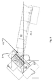
- FIG. 7 illustrates a first part 3 of a cradle dock placed against one of the broad sides and the bottom of the hull of a vessel resting at the bottom as Costa Concordia.
- the first part of the cradle dock having an L-shaped cross section as illustrated, is brought in position by means of ship section or barge 40.
- the illustrated barge 40 is made by cutting the aft part of a ship to be scrapped, closing the aft end to avoid uncontrolled/unwanted inflow of water into the hull, and mounting of one or more hinge connectors 41 for pivotally connecting the barge to a buoyancy tank, pontoon, or a part of a cradle dock as described herein. If more than one hinge connector is present, the hinge connectors 41, have a common axis of rotation about which the first cradle part 3 and the barge 40 rotate. The axis of rotation about the hinge connector(s) 41 is substantially parallel with the sea, or horizontal, and substantially perpendicular to the length of the barge 40.
- the top of the side pontoon 5 may be welded to the broad side of the vessel 1 to be salvaged during the positioning operation.
- the barge 40 is ballasted at the aft end to allow the top of the side pontoon 5 to rest at an acute angle onto the broad side of the vessel 1.
- the top of the side pontoon is then welded to the vessel 1.
- the barge, and if needed also the top pontoon 5 and bottom pontoon 6, forming the first cradle dock part 3, is (are) trimmed to allow both the side pontoon 5 and the bottom pontoon 6 to rest against the broad side and the bottom of the vessel, respectively.
- the inside of the suction pads and any habitats are then vented to the atmosphere and the water therein is pumped out, to form a suction force between the vessel 1 and the suction pads, and the vessel and any habitats.
- the cradle dock first part 3 may then be further connected to the vessel by means of welding. If habitats are present, the welding connections may be made by personnel or robots from the inside of the habitats.
- the barge After welding the cradle dock first part 3 to the vessel 1, the barge is trimmed by emptying ballast tanks in the aft part, and filling ballast tanks in the bow part thereof for lowering the bow, and lifting the aft part of the barge to get the vessel and cradle dock parts in a second, or lifted position, and thereby also the cradle dock first part 3 and the vessel 1 sufficiently to move the connected parts. If the side and/or bottom pontoons 5, 6 are trimmed by fully or partly filling the pontoons with water, the water inside the pontoons 5, 6 the trim of the pontoons may be adjusted co-ordinately with the trimming of the barge 40.
- the second cradle dock part(s) 30 may be fitted onto the vessel 1, and be welded to the vessel as for the first cradle part 3.
- the second cradle part 30 may also be connected to a second cradle part bottom section 31 to give a L-shaped section, or the second cradle part bottom section may be introduced after the second cradle part is fastened.
- the second cradle part 30 and the second cradle part bottom section are also provided with suction pads 10 and friction fenders 11 to keep the vessel and the second cradle part together and substantially reduce the relative movement between the cradle part and the vessel to allow welding.
- the barge 40 may be trimmed to lower the vessel and completed cradle 2 so that the vessel 1 and cradle dock 2 are in their upright position.
- the skilled person will understand that the pontoons of the cradle 2 have to be trimmed correspondingly to stabilize the vessel and cradle dock in this position.
- the aft part of the barge 40 may again be lowered by re-trimming the barge, to a 4 th position illustrated in figure 9 .
- the floating unit comprising the cradle dock 2 and the vessel 1
- the floating unit is a stable unit that may be towed to a final destination.
- Calculation on an embodiment designed for salvage of Costa Concordia has concluded that the stability of this floating unit is fulfilling the requirements set by relevant authorities to be towed to the destination for the vessel.
- FIGs 10 and 11 illustrate an alternative connection process for connecting a pontoon 35 to a vessel 1.
- the vessel is either stabilized in a non illustrated way at the opposite side, e.g. as illustrated with reference to figure 7 , or rests in an upright position at the sea bed.
- the pontoon is partly filled with water and lowered and oriented relative to the vessel by means of cranes.
- the pontoon 35 is lowered to the intended depth, and oriented so that a lower edge of the side wall of the pontoon 35 to be arranged towards the hull of the vessel, rests against the lower part of the broad side of the hull and the pontoon attacks the hull at an acute angle, as illustrated in figure 10 .
- the top of the pontoon is then pulled by means of the cranes towards the vessel until suction pads arranged on the pontoon rest against the side of the vessel, as illustrated in figure 11 .
- the suction pads are then activated by pumping out water thereof and substituting the water with air at lower than the ambient pressure, such as atmospheric pressure.
- Habitat(s) 20 arranged at the pontoon 35 is then prepared for use by emptying the habitats for water, and substituting the water with air, preferably at atmospheric pressure.
- the pontoon 35 is welded to the hull of the vessel to produce a secure connection between the vessel and the pontoon, as described above. The same procedure may then be repeated for additional pontoons at the same side or the opposite side.
- FIG 11 illustrates the vessel after being lifted to the surface, but for the purpose of simplification, only the pontoon 35 at one side is illustrated.
- the skilled may will, however, understand the pontoons are necessary at both sides of the vessel to stabilize the floating unit comprising the vessel and pontoons.
- bottom pontoons i.e. pontoons supporting the bottom of the vessel and preferably connecting the side pontoons 35 as illustrated below, may be placed below the bottom of the vessel, and carefully lifted towards the bottom by means of cranes and trimming of the buoyancy of the bottom pontoon(s) after the vessel illustrated in figures 10 and 11 is lifted above the sea bed and at least partly lifted to the surface.
- suction pads and habitats is arranged at the upwards directed surface of bottom pontoon, where the suction pads are arranged to ascertain a stable connection between the pontoon during welding operations performed inside the habitat(s).
- both the first and second cradle dock parts in some of the illustrations are L-shaped, and that only the first cradle dock part is L-shaped in some figures.
- both L-shaped and straight pontoons are applicable according to the present invention.
- the configuration of the pontoons is dependent on the vessel to be salvaged, the position thereof, the water depth, and other considerations.
- the present method and devices may be mounted at the vessel as separate tanks, or pontoons as described above, and any combination of separate tanks and pontoons without leaving the scope of the invention.
- the invention may also be applicable for salvage of marine vessels with no or limited flat areas, such as e.g., but not limited to submarines, provided that the pontoons or tanks have a mating surface corresponding to the surface of the vessel in question.
Landscapes
- Engineering & Computer Science (AREA)
- Mechanical Engineering (AREA)
- Ocean & Marine Engineering (AREA)
- Chemical & Material Sciences (AREA)
- Combustion & Propulsion (AREA)
- Bridges Or Land Bridges (AREA)
- Hooks, Suction Cups, And Attachment By Adhesive Means (AREA)
- Supports Or Holders For Household Use (AREA)
- Details Of Rigid Or Semi-Rigid Containers (AREA)
Claims (13)
- Verfahren zum Bergen eines teilweise oder vollständig gesunkenen Schiffs, wobei das Verfahren umfasst:a) Anordnen eines oder mehrerer Ponton(s) (5, 6), welches mit einem Saugkissen (10) ausgestattet ist, auf einer geeigneten Oberfläche des Schiffs (1);b) Verbinden des einen oder der mehreren Ponton(s) (5, 6) mit der Oberfläche des Schiffs (1) durch Auspumpen von Wasser aus dem/den Saugkissen (10), um eine Haltekraft zwischen dem/den Ponton(s) (5, 6) und der Oberfläche des Schiffs (1) zu erzeugen;c) Verlagern des Schiffs (1) und des/der Pontons (5, 6) zu einer zweiten Position durch Ausüben einer Kraft auf das/die Ponton(s) (5, 6).
- Verfahren nach Anspruch 1, wobei Reibkissen (11) auf dem Ponton (5, 6) so angeordnet sind, dass der Ponton (5, 6) durch die durch die Saugkissen (10) erzeugte Ansaugkraft gegen die Oberfläche des Schiffs (1) gezwungen wird.
- Verfahren nach Anspruch 1 oder 2, weiterhin umfassend den Schritt den einen oder die mehreren Ponton(s) (5, 6) an der Oberfläche des Schiffs (1) sicher zu befestigen.
- Verfahren nach Anspruch 3, wobei das sichere Befestigen durch Schweißen des/der Ponton(s) (5, 6) an das Schiff gemacht wird.
- Verfahren nach Anspruch 3 oder 4, wobei der Schritt des sicheren Befestigens zwischen den Schritten b) und c) gemacht wird.
- Verfahren nach Anspruch 3 oder 4, wobei der Schritt des sicheren Befestigens nach dem Schritt c) gemacht wird.
- Verfahren nach einem der vorhergehenden Ansprüche, wobei ein Habitat (20) in einem zwischen dem Ponton (5, 6) und der Oberfläche des Schiffs (1) definierten Raum angeordnet ist, um einen trockenen Zugang zu dem Raum zu ermöglichen.
- Verfahren nach einem der vorhergehenden Ansprüche, wobei die Pontons (5, 6) nach dem Verbinden mit dem Schiff (1) durch Ersetzen von Wasser in den Pontons (5, 6) mit Luft getrimmt werden können, um das Schiff (1) zu verlagern.
- Verfahren nach einem der vorhergehenden Ansprüche, wobei ein oder mehrere Ponton(s) (5, 6) mit einem Schleppkahn (40) verbunden wird/werden, und dass die zur Verlagerung des Schiffs (1) ausgeübten Kräfte durch Anpassung der Trimmung des Schleppkahns (40) ausgeübt werden.
- Verfahren nach einem der Ansprüche 1-8, wobei eines oder mehrere der Pontons mit Hubseilen zur Verlagerung des Schiffs (1) verbunden ist/sind.
- System zum Bergen eines teilweise oder vollständig gesunkenen Schiffs (1), wobei das System umfasst
ein oder mehrere Ponton(s) (5, 6), wobei an dem/den Ponton(s) Saugkissen zum Erzeugen einer Haltekraft zwischen dem/den Ponton(s) und der/den Oberfläche(n) des Schiffs (1) sind. - System nach Anspruch 11, wobei ein oder mehrere Habitat(s) (20) seitlich des/der Ponton(s) (5, 6) neben der Oberfläche zum Vorsehen einer trockenen unterseeischen Umgebung zum Schweißen des/der Ponton(s) an die Oberfläche(n) angeordnet sind.
- System nach Anspruch 11 oder 12, wobei das System weiterhin ein oder mehrere mit dem einen oder den mehreren Ponton(s) (5, 6) verbundene Hebevorrichtung(en) zur Verlagerung der Pontons (5, 6) und des Schiffs (1) umfasst.
Applications Claiming Priority (2)
| Application Number | Priority Date | Filing Date | Title |
|---|---|---|---|
| NO20120912A NO336829B1 (no) | 2012-08-15 | 2012-08-15 | Berging av skip med oppdriftsmidler festet med sugekopper |
| PCT/EP2013/067001 WO2014027029A1 (en) | 2012-08-15 | 2013-08-14 | Method and system for salvage of vessels |
Publications (2)
| Publication Number | Publication Date |
|---|---|
| EP2885201A1 EP2885201A1 (de) | 2015-06-24 |
| EP2885201B1 true EP2885201B1 (de) | 2016-09-28 |
Family
ID=48985763
Family Applications (1)
| Application Number | Title | Priority Date | Filing Date |
|---|---|---|---|
| EP13748328.5A Active EP2885201B1 (de) | 2012-08-15 | 2013-08-14 | Schiffsbergungssytem und -verfahren |
Country Status (3)
| Country | Link |
|---|---|
| EP (1) | EP2885201B1 (de) |
| NO (1) | NO336829B1 (de) |
| WO (1) | WO2014027029A1 (de) |
Families Citing this family (1)
| Publication number | Priority date | Publication date | Assignee | Title |
|---|---|---|---|---|
| GB2601005B (en) * | 2020-11-17 | 2024-12-04 | Animal Dynamics Ltd | Suction device and tracking device comprising the same |
Family Cites Families (4)
| Publication number | Priority date | Publication date | Assignee | Title |
|---|---|---|---|---|
| GB186368A (en) * | 1921-04-27 | 1922-09-27 | Jesse Wilford Reno | Method and apparatus for raising sunken ships |
| US3853345A (en) * | 1973-11-30 | 1974-12-10 | Us Navy | Suction gripping device |
| US4872781A (en) * | 1988-11-18 | 1989-10-10 | Childress Joseph B | Open top floatable barge repair box with barge to box sealing system |
| NO992814D0 (no) * | 1999-06-09 | 1999-06-09 | Hitec Marine As | System for lasting/lossing av fluidprodukter |
-
2012
- 2012-08-15 NO NO20120912A patent/NO336829B1/no unknown
-
2013
- 2013-08-14 EP EP13748328.5A patent/EP2885201B1/de active Active
- 2013-08-14 WO PCT/EP2013/067001 patent/WO2014027029A1/en not_active Ceased
Also Published As
| Publication number | Publication date |
|---|---|
| EP2885201A1 (de) | 2015-06-24 |
| WO2014027029A1 (en) | 2014-02-20 |
| NO336829B1 (no) | 2015-11-09 |
| NO20120912A1 (no) | 2014-02-17 |
Similar Documents
| Publication | Publication Date | Title |
|---|---|---|
| US5860765A (en) | In-water dry dock system with removable centerline insert | |
| WO2018074977A1 (en) | System and method for reconfiguring a mobile docking apparatus for transporting, removal, installation, housing and transferring assets | |
| KR20100124734A (ko) | 분리 가능한 바닥부/표면 연결 덕트용의 도킹 부표를 갖는 릴을 포함하는 지지물 | |
| CN102762445A (zh) | 回收和部署船舶的近海装置 | |
| US9061749B2 (en) | Method for dry-docking a floating unit | |
| CN1437543A (zh) | 可潜入水中的提升重物的双体船 | |
| CN100482532C (zh) | 用于遇难船只的营救船、船只营救方法以及营救船的应用 | |
| CA2900357C (en) | An integrated heavy lift and logistics vessel | |
| GB2315464A (en) | Transporting offshore structures | |
| EP2885201B1 (de) | Schiffsbergungssytem und -verfahren | |
| US20190106854A1 (en) | Systems, apparatuses, and methods for removing fixed offshore platforms | |
| CN101410291A (zh) | 浮桥,船坞及用于船坞的方法 | |
| KR101701287B1 (ko) | 코퍼댐을 이용한 시추선 하부구조물 설치 및 해제방법 | |
| WO2022218485A1 (en) | A method and system of ballasting and deballasting a vessel | |
| DK181608B1 (en) | A variable draft vessel and a method and system of deballasting a vessel | |
| CN221809815U (zh) | 一种分体式打捞船 | |
| KR101526365B1 (ko) | 선박 및 선박의 배치 방법 | |
| WO2017164919A1 (en) | Systems, apparatuses, and methods for removing fixed offshore platforms | |
| US8857362B2 (en) | Mobile marine service module | |
| Austin | Offshore Rig Types | |
| Bartholomew | The salvage of the litton launching platform | |
| Rutkowski | Numerical Analysis of the Contact Forces Generated on a „Hiload DP1” Prototype Attachment System at Calm Sea | |
| HRP20010064A2 (en) | Process for repairing submersed plane bottomed structures by means of a lift cylinder | |
| HK1172300B (en) | Offshore equipment deploying and retrieving vessel |
Legal Events
| Date | Code | Title | Description |
|---|---|---|---|
| PUAI | Public reference made under article 153(3) epc to a published international application that has entered the european phase |
Free format text: ORIGINAL CODE: 0009012 |
|
| 17P | Request for examination filed |
Effective date: 20150213 |
|
| AK | Designated contracting states |
Kind code of ref document: A1 Designated state(s): AL AT BE BG CH CY CZ DE DK EE ES FI FR GB GR HR HU IE IS IT LI LT LU LV MC MK MT NL NO PL PT RO RS SE SI SK SM TR |
|
| AX | Request for extension of the european patent |
Extension state: BA ME |
|
| DAX | Request for extension of the european patent (deleted) | ||
| RAP1 | Party data changed (applicant data changed or rights of an application transferred) |
Owner name: NORWEGIAN SALVAGE INNOVATION AS |
|
| GRAP | Despatch of communication of intention to grant a patent |
Free format text: ORIGINAL CODE: EPIDOSNIGR1 |
|
| INTG | Intention to grant announced |
Effective date: 20160608 |
|
| GRAS | Grant fee paid |
Free format text: ORIGINAL CODE: EPIDOSNIGR3 |
|
| GRAA | (expected) grant |
Free format text: ORIGINAL CODE: 0009210 |
|
| AK | Designated contracting states |
Kind code of ref document: B1 Designated state(s): AL AT BE BG CH CY CZ DE DK EE ES FI FR GB GR HR HU IE IS IT LI LT LU LV MC MK MT NL NO PL PT RO RS SE SI SK SM TR |
|
| REG | Reference to a national code |
Ref country code: GB Ref legal event code: FG4D |
|
| REG | Reference to a national code |
Ref country code: CH Ref legal event code: EP |
|
| REG | Reference to a national code |
Ref country code: AT Ref legal event code: REF Ref document number: 832482 Country of ref document: AT Kind code of ref document: T Effective date: 20161015 |
|
| REG | Reference to a national code |
Ref country code: IE Ref legal event code: FG4D |
|
| REG | Reference to a national code |
Ref country code: DE Ref legal event code: R096 Ref document number: 602013012202 Country of ref document: DE |
|
| REG | Reference to a national code |
Ref country code: LT Ref legal event code: MG4D |
|
| PG25 | Lapsed in a contracting state [announced via postgrant information from national office to epo] |
Ref country code: NO Free format text: LAPSE BECAUSE OF FAILURE TO SUBMIT A TRANSLATION OF THE DESCRIPTION OR TO PAY THE FEE WITHIN THE PRESCRIBED TIME-LIMIT Effective date: 20161228 Ref country code: FI Free format text: LAPSE BECAUSE OF FAILURE TO SUBMIT A TRANSLATION OF THE DESCRIPTION OR TO PAY THE FEE WITHIN THE PRESCRIBED TIME-LIMIT Effective date: 20160928 Ref country code: HR Free format text: LAPSE BECAUSE OF FAILURE TO SUBMIT A TRANSLATION OF THE DESCRIPTION OR TO PAY THE FEE WITHIN THE PRESCRIBED TIME-LIMIT Effective date: 20160928 Ref country code: RS Free format text: LAPSE BECAUSE OF FAILURE TO SUBMIT A TRANSLATION OF THE DESCRIPTION OR TO PAY THE FEE WITHIN THE PRESCRIBED TIME-LIMIT Effective date: 20160928 Ref country code: LT Free format text: LAPSE BECAUSE OF FAILURE TO SUBMIT A TRANSLATION OF THE DESCRIPTION OR TO PAY THE FEE WITHIN THE PRESCRIBED TIME-LIMIT Effective date: 20160928 |
|
| REG | Reference to a national code |
Ref country code: NL Ref legal event code: MP Effective date: 20160928 |
|
| REG | Reference to a national code |
Ref country code: AT Ref legal event code: MK05 Ref document number: 832482 Country of ref document: AT Kind code of ref document: T Effective date: 20160928 |
|
| PG25 | Lapsed in a contracting state [announced via postgrant information from national office to epo] |
Ref country code: SE Free format text: LAPSE BECAUSE OF FAILURE TO SUBMIT A TRANSLATION OF THE DESCRIPTION OR TO PAY THE FEE WITHIN THE PRESCRIBED TIME-LIMIT Effective date: 20160928 Ref country code: NL Free format text: LAPSE BECAUSE OF FAILURE TO SUBMIT A TRANSLATION OF THE DESCRIPTION OR TO PAY THE FEE WITHIN THE PRESCRIBED TIME-LIMIT Effective date: 20160928 Ref country code: LV Free format text: LAPSE BECAUSE OF FAILURE TO SUBMIT A TRANSLATION OF THE DESCRIPTION OR TO PAY THE FEE WITHIN THE PRESCRIBED TIME-LIMIT Effective date: 20160928 Ref country code: GR Free format text: LAPSE BECAUSE OF FAILURE TO SUBMIT A TRANSLATION OF THE DESCRIPTION OR TO PAY THE FEE WITHIN THE PRESCRIBED TIME-LIMIT Effective date: 20161229 |
|
| PG25 | Lapsed in a contracting state [announced via postgrant information from national office to epo] |
Ref country code: RO Free format text: LAPSE BECAUSE OF FAILURE TO SUBMIT A TRANSLATION OF THE DESCRIPTION OR TO PAY THE FEE WITHIN THE PRESCRIBED TIME-LIMIT Effective date: 20160928 Ref country code: EE Free format text: LAPSE BECAUSE OF FAILURE TO SUBMIT A TRANSLATION OF THE DESCRIPTION OR TO PAY THE FEE WITHIN THE PRESCRIBED TIME-LIMIT Effective date: 20160928 |
|
| PG25 | Lapsed in a contracting state [announced via postgrant information from national office to epo] |
Ref country code: SK Free format text: LAPSE BECAUSE OF FAILURE TO SUBMIT A TRANSLATION OF THE DESCRIPTION OR TO PAY THE FEE WITHIN THE PRESCRIBED TIME-LIMIT Effective date: 20160928 Ref country code: ES Free format text: LAPSE BECAUSE OF FAILURE TO SUBMIT A TRANSLATION OF THE DESCRIPTION OR TO PAY THE FEE WITHIN THE PRESCRIBED TIME-LIMIT Effective date: 20160928 Ref country code: PL Free format text: LAPSE BECAUSE OF FAILURE TO SUBMIT A TRANSLATION OF THE DESCRIPTION OR TO PAY THE FEE WITHIN THE PRESCRIBED TIME-LIMIT Effective date: 20160928 Ref country code: CZ Free format text: LAPSE BECAUSE OF FAILURE TO SUBMIT A TRANSLATION OF THE DESCRIPTION OR TO PAY THE FEE WITHIN THE PRESCRIBED TIME-LIMIT Effective date: 20160928 Ref country code: SM Free format text: LAPSE BECAUSE OF FAILURE TO SUBMIT A TRANSLATION OF THE DESCRIPTION OR TO PAY THE FEE WITHIN THE PRESCRIBED TIME-LIMIT Effective date: 20160928 Ref country code: BG Free format text: LAPSE BECAUSE OF FAILURE TO SUBMIT A TRANSLATION OF THE DESCRIPTION OR TO PAY THE FEE WITHIN THE PRESCRIBED TIME-LIMIT Effective date: 20161228 Ref country code: PT Free format text: LAPSE BECAUSE OF FAILURE TO SUBMIT A TRANSLATION OF THE DESCRIPTION OR TO PAY THE FEE WITHIN THE PRESCRIBED TIME-LIMIT Effective date: 20170130 Ref country code: AT Free format text: LAPSE BECAUSE OF FAILURE TO SUBMIT A TRANSLATION OF THE DESCRIPTION OR TO PAY THE FEE WITHIN THE PRESCRIBED TIME-LIMIT Effective date: 20160928 Ref country code: BE Free format text: LAPSE BECAUSE OF FAILURE TO SUBMIT A TRANSLATION OF THE DESCRIPTION OR TO PAY THE FEE WITHIN THE PRESCRIBED TIME-LIMIT Effective date: 20160928 Ref country code: IS Free format text: LAPSE BECAUSE OF FAILURE TO SUBMIT A TRANSLATION OF THE DESCRIPTION OR TO PAY THE FEE WITHIN THE PRESCRIBED TIME-LIMIT Effective date: 20170128 |
|
| REG | Reference to a national code |
Ref country code: DE Ref legal event code: R097 Ref document number: 602013012202 Country of ref document: DE |
|
| PG25 | Lapsed in a contracting state [announced via postgrant information from national office to epo] |
Ref country code: IT Free format text: LAPSE BECAUSE OF FAILURE TO SUBMIT A TRANSLATION OF THE DESCRIPTION OR TO PAY THE FEE WITHIN THE PRESCRIBED TIME-LIMIT Effective date: 20160928 |
|
| PG25 | Lapsed in a contracting state [announced via postgrant information from national office to epo] |
Ref country code: DK Free format text: LAPSE BECAUSE OF FAILURE TO SUBMIT A TRANSLATION OF THE DESCRIPTION OR TO PAY THE FEE WITHIN THE PRESCRIBED TIME-LIMIT Effective date: 20160928 |
|
| PLBE | No opposition filed within time limit |
Free format text: ORIGINAL CODE: 0009261 |
|
| STAA | Information on the status of an ep patent application or granted ep patent |
Free format text: STATUS: NO OPPOSITION FILED WITHIN TIME LIMIT |
|
| 26N | No opposition filed |
Effective date: 20170629 |
|
| PG25 | Lapsed in a contracting state [announced via postgrant information from national office to epo] |
Ref country code: SI Free format text: LAPSE BECAUSE OF FAILURE TO SUBMIT A TRANSLATION OF THE DESCRIPTION OR TO PAY THE FEE WITHIN THE PRESCRIBED TIME-LIMIT Effective date: 20160928 |
|
| REG | Reference to a national code |
Ref country code: DE Ref legal event code: R119 Ref document number: 602013012202 Country of ref document: DE |
|
| REG | Reference to a national code |
Ref country code: CH Ref legal event code: PL |
|
| PG25 | Lapsed in a contracting state [announced via postgrant information from national office to epo] |
Ref country code: MC Free format text: LAPSE BECAUSE OF FAILURE TO SUBMIT A TRANSLATION OF THE DESCRIPTION OR TO PAY THE FEE WITHIN THE PRESCRIBED TIME-LIMIT Effective date: 20160928 |
|
| PG25 | Lapsed in a contracting state [announced via postgrant information from national office to epo] |
Ref country code: CH Free format text: LAPSE BECAUSE OF NON-PAYMENT OF DUE FEES Effective date: 20170831 Ref country code: LI Free format text: LAPSE BECAUSE OF NON-PAYMENT OF DUE FEES Effective date: 20170831 |
|
| REG | Reference to a national code |
Ref country code: FR Ref legal event code: ST Effective date: 20180430 |
|
| REG | Reference to a national code |
Ref country code: IE Ref legal event code: MM4A |
|
| PG25 | Lapsed in a contracting state [announced via postgrant information from national office to epo] |
Ref country code: LU Free format text: LAPSE BECAUSE OF NON-PAYMENT OF DUE FEES Effective date: 20170814 |
|
| PG25 | Lapsed in a contracting state [announced via postgrant information from national office to epo] |
Ref country code: DE Free format text: LAPSE BECAUSE OF NON-PAYMENT OF DUE FEES Effective date: 20180301 Ref country code: IE Free format text: LAPSE BECAUSE OF NON-PAYMENT OF DUE FEES Effective date: 20170814 |
|
| PG25 | Lapsed in a contracting state [announced via postgrant information from national office to epo] |
Ref country code: FR Free format text: LAPSE BECAUSE OF NON-PAYMENT OF DUE FEES Effective date: 20170831 |
|
| PG25 | Lapsed in a contracting state [announced via postgrant information from national office to epo] |
Ref country code: MT Free format text: LAPSE BECAUSE OF NON-PAYMENT OF DUE FEES Effective date: 20170814 |
|
| PG25 | Lapsed in a contracting state [announced via postgrant information from national office to epo] |
Ref country code: AL Free format text: LAPSE BECAUSE OF FAILURE TO SUBMIT A TRANSLATION OF THE DESCRIPTION OR TO PAY THE FEE WITHIN THE PRESCRIBED TIME-LIMIT Effective date: 20160928 |
|
| PG25 | Lapsed in a contracting state [announced via postgrant information from national office to epo] |
Ref country code: HU Free format text: LAPSE BECAUSE OF FAILURE TO SUBMIT A TRANSLATION OF THE DESCRIPTION OR TO PAY THE FEE WITHIN THE PRESCRIBED TIME-LIMIT; INVALID AB INITIO Effective date: 20130814 |
|
| PG25 | Lapsed in a contracting state [announced via postgrant information from national office to epo] |
Ref country code: CY Free format text: LAPSE BECAUSE OF FAILURE TO SUBMIT A TRANSLATION OF THE DESCRIPTION OR TO PAY THE FEE WITHIN THE PRESCRIBED TIME-LIMIT Effective date: 20160928 |
|
| PG25 | Lapsed in a contracting state [announced via postgrant information from national office to epo] |
Ref country code: MK Free format text: LAPSE BECAUSE OF FAILURE TO SUBMIT A TRANSLATION OF THE DESCRIPTION OR TO PAY THE FEE WITHIN THE PRESCRIBED TIME-LIMIT Effective date: 20160928 |
|
| PG25 | Lapsed in a contracting state [announced via postgrant information from national office to epo] |
Ref country code: TR Free format text: LAPSE BECAUSE OF FAILURE TO SUBMIT A TRANSLATION OF THE DESCRIPTION OR TO PAY THE FEE WITHIN THE PRESCRIBED TIME-LIMIT Effective date: 20160928 |
|
| PGFP | Annual fee paid to national office [announced via postgrant information from national office to epo] |
Ref country code: GB Payment date: 20250819 Year of fee payment: 13 |