EP2885457B1 - Rouleau et procédé pour la production et/ou la transformation d'une bande de papier, de carton ou de papier ouaté - Google Patents
Rouleau et procédé pour la production et/ou la transformation d'une bande de papier, de carton ou de papier ouaté Download PDFInfo
- Publication number
- EP2885457B1 EP2885457B1 EP13747838.4A EP13747838A EP2885457B1 EP 2885457 B1 EP2885457 B1 EP 2885457B1 EP 13747838 A EP13747838 A EP 13747838A EP 2885457 B1 EP2885457 B1 EP 2885457B1
- Authority
- EP
- European Patent Office
- Prior art keywords
- roller
- sealing strip
- sealing
- lubricant
- line portion
- Prior art date
- Legal status (The legal status is an assumption and is not a legal conclusion. Google has not performed a legal analysis and makes no representation as to the accuracy of the status listed.)
- Active
Links
Images


Classifications
-
- F—MECHANICAL ENGINEERING; LIGHTING; HEATING; WEAPONS; BLASTING
- F16—ENGINEERING ELEMENTS AND UNITS; GENERAL MEASURES FOR PRODUCING AND MAINTAINING EFFECTIVE FUNCTIONING OF MACHINES OR INSTALLATIONS; THERMAL INSULATION IN GENERAL
- F16J—PISTONS; CYLINDERS; SEALINGS
- F16J15/00—Sealings
- F16J15/16—Sealings between relatively-moving surfaces
- F16J15/162—Special parts or details relating to lubrication or cooling of the sealing itself
-
- D—TEXTILES; PAPER
- D21—PAPER-MAKING; PRODUCTION OF CELLULOSE
- D21F—PAPER-MAKING MACHINES; METHODS OF PRODUCING PAPER THEREON
- D21F3/00—Press section of machines for making continuous webs of paper
- D21F3/02—Wet presses
- D21F3/10—Suction rolls, e.g. couch rolls
-
- D—TEXTILES; PAPER
- D21—PAPER-MAKING; PRODUCTION OF CELLULOSE
- D21F—PAPER-MAKING MACHINES; METHODS OF PRODUCING PAPER THEREON
- D21F7/00—Other details of machines for making continuous webs of paper
-
- F—MECHANICAL ENGINEERING; LIGHTING; HEATING; WEAPONS; BLASTING
- F16—ENGINEERING ELEMENTS AND UNITS; GENERAL MEASURES FOR PRODUCING AND MAINTAINING EFFECTIVE FUNCTIONING OF MACHINES OR INSTALLATIONS; THERMAL INSULATION IN GENERAL
- F16C—SHAFTS; FLEXIBLE SHAFTS; ELEMENTS OR CRANKSHAFT MECHANISMS; ROTARY BODIES OTHER THAN GEARING ELEMENTS; BEARINGS
- F16C13/00—Rolls, drums, discs, or the like; Bearings or mountings therefor
Definitions
- the invention relates to a roller with a sealing device for sealing an overpressure or underpressure zone of the roller according to the preamble of patent claim 1 and to a method for producing and / or processing a paper, board or tissue web according to the preamble of patent claim 16
- Sealing devices in suctioned or blown rolls for paper, board or tissue machines must reliably seal the overpressure or underpressure zone against the environment in which normal pressure prevails.
- the sealing surface of each sealing strip of the sealing device is employed against the inside of the rotating roll shell to seal the overpressure or vacuum zone.
- To reduce the wear of the sealing strip caused by friction between the lateral surface and the sealing surface is trying to introduce a lubricant between the sealing surface and the inside. This is usually done with spray tubes, are arranged in the direction of rotation of the roller in front of the first sealing strip of the positive or negative pressure zone.
- the lubricant is applied to the inside of the roll shell of this transported by its rotation to the individual sealing strips, whereby the viewed in the direction of rotation decreases the lubricant supply from sealing strip to sealing strip.
- a large amount of lubricant must be used, which but only for a small part of the actual lubrication of the sealing strips to good and otherwise contributes to unwanted rewetting of the fibrous web.
- an invention of the Applicant proposes to direct the lubricant directly to the upper surface of the respective sealing strip, which provides the sealing surface, in order to provide each individual sealing strip with the required one Supply amount of lubricant.
- a preferred embodiment of this invention further proposes here a lubricant channel provided on the upper side of the roller in the form of a groove-like depression extending in the longitudinal direction of the sealing strip, ie in the cross-machine direction of the roller.
- a roller with a sealing device for sealing an overpressure or underpressure zone of the roller and with a roller shell movable relative to the sealing device comprising a sealing strip bordered in its length by two ends with an upper side and the upper side a sealing surface and a lubricant channel adjoining the sealing surface is provided, wherein the lubricant channel is formed by at least one groove-like recess extending in the longitudinal direction of the sealing strip in the sealing strip and the sealing surface and the opening of the groove-like depression to the inside of the roll shell, the lubricant groove on at least one at least in sections within the sealing strip extending supply line is connected, by means of which a lubricant between the inside of the roll shell and the sealing surface can be brought.
- the invention is characterized in that the sealing strip in the region of its two ends in each case has a wall which terminate the lubricant channel in its length.
- the lubricant channel is completed on both sides in its length, this is formed like a trough, whereby a uniform over the length of the lubricant groove level of lubricant can be adjusted and the lubricant groove forms a kind of memory for the lubricant.
- a substantially constant level of lubricant can be maintained.
- the amount of lubricant required can be further reduced and the emergency running properties can be improved with short-term failure of the lubricant supply.
- the lubricant groove extends substantially over the entire length of the sealing strip. In essence, this means that the lubricant channel extends over at least 90% of the length of the sealing strip. In this case, the lubricant channel can extend uninterrupted.
- the two the lubricant channel in their length limiting walls have a strength - viewed in the longitudinal direction of the sealing strip - a maximum of 20 cm, preferably maximum 10cm. In a conventional sealing strip, this may mean that the lubricant channel extends over several meters, whereas the two walls at the ends of the sealing strip each extend over a maximum of 20 cm, in particular a maximum of 10 cm.
- a preferred embodiment of the invention provides that the supply line within the sealing strip along the longitudinal direction extending central supply channel and at least one, preferably a plurality of the lubricant channel and the central supply channel interconnecting riser (s) comprises via which the lubricant channel is fed by ending in the lubricant groove outlet openings of the respective riser with the lubricant.
- the central supply channel can be fed by one or a few feed lines with the lubricant.
- the central supply channel then distributes the lubricant to several risers - the number of risers is significantly greater than the number of leads. It is conceivable in this context that viewed in the longitudinal direction of the sealing strip about every 5 to 500mm an outlet opening is arranged.
- a further advantageous embodiment of the invention provides that the central supply channel has a changing cross-sectional area and / or cross-sectional geometry along its longitudinal extent.
- a central supply channel with varying cross-section can be produced in a particularly simple manner by, for example, first introducing into the base body of the sealing strip a groove, for example a U-shaped groove, open to one of the long sides of the main body, the opening then then partially opening with sealing strip material for example by means of a width and length but not depth of the groove replicating profile body is closed.
- This profile body can then be attached, for example, by gluing to the base body and together with it form a channel which provides the central supply channel.
- a preferred embodiment of the invention provides that the sealing surface and the lubricant groove are arranged on the top, that considered when properly installed the sealing device in the roller in the intended direction of rotation of the roll shell, the lubricant groove the essential part the sealing surface, in particular that the lubricant groove upstream of the entire sealing surface. This ensures that the inside of the roll shell is wetted with the lubricant directly before it runs onto the sealing surface or at least the essential part of the sealing surface.
- a further preferred embodiment of the invention provides that the sealing strip is limited in width by a front and a rear end face and extends the top of the sealing strip between the front and the rear end, wherein the front - and rear end face and the Sealing surface and the lubricant channel are arranged such that when properly installed the sealing device in the roller and in the intended direction of rotation of the roll shell viewed, the roll shell runs in the front end on the sealing strip runs first the lubricant channel and then the sealing surface over in the region of the back from the sealing strip expires.
- the lubricant channel has a bed forming the deepest point of the lubricant channel with a front side wall extending to the front end side and a rear side wall extending to the sealing surface.
- the upper edge of the front side wall adjoins, in particular, the front end side
- the upper edge of the rear side wall adjoins, in particular, the sealing surface. It is preferably provided that, when the sealing device is installed as intended in a roller, a straight line connecting the two upper edges with the horizontal assumes an angle of 1 ° -89 °, in particular an angle of 15 ° or more and 80 ° or less.
- the straight line connecting the two upper edges forms a type of wedge-shaped gap between the upper side of the sealing strip and the inner side of the roll mantle, which is greatest at the front end side and tapers towards the sealing surface.
- a suction effect is achieved by the entrained with the rotating roll shell air, which draws the lubricant with in the gap between the inside of the roll shell and sealing surface.
- the rear end closer to the inside of the roll shell as the front end, in particular, the rear end extends to the inside of the Roll shell whereas the front end side does not extend to the inside of the roll shell.
- the front and the back of the sealing strip extend substantially parallel to each other.
- a further preferred embodiment of the invention provides that the sealing device comprises a sealing strip holder for holding the sealing strip, wherein the sealing strip holder has a holding section with at least one guide surface the sealing strip is displaceably mounted with at least one of the two sides of the front and rear sides, whereby the sealing strip can be displaced from and to the inside of the roll lateral surface when the sealing device is installed in the roll as intended along the path in the radial direction of the roll.
- the supply line is led out at least one point on one of the two end sides of the sealing strip and wherein the holding portion has at least one recess through which the led out of the end face of the sealing strip gate of the supply line is passed through the sealing strip holder, wherein the at least one recess is formed such that the sealing strip is movable together with the lead-out portion of the supply line relative to the sealing strip holder along the path.
- the at least one recess is formed as a hole or as an upwardly open groove.
- the portion of the supply line which extends outside the sealing strip but within the roller has a rigid first line section and a second line section bendable relative thereto, or is formed therefrom.
- the bendable second line section is substantially shorter than the less rigid first line section.
- the bend-flexible, short second line section Due to the bend-flexible, short second line section, a free displaceability of the sealing strip relative to the sealing strip holder towards the inside of the roll shell is ensured in the radial direction of the roll.
- the first line section of the inside of the roller but outside the sealing strip extending part of the supply line can be resistant to bending and therefore executed stable become.
- the bend flexible second line section is particularly important to ensure that it runs so that it does not scrub during movement of the sealing strip on components within the roller.
- steel pipes can be used for the first pipe section.
- a rubber hose can be used for the second line section, which can be reinforced, for example, with a steel braid.
- the bending-resistant first line section prefferably begins at the at least one end of the roll and to extend in the direction of the sealing strip in the roll. It is also conceivable that the flexurally flexible second line section at a maximum distance of one meter from the at least one point begins at which the supply line is guided out of the sealing strip. In order to track at least the wear path of the sealing strip is particularly conceivable that the flexible second conduit section has a length in the range of 15cm to 200cm, in particular a length in the range of 20cm to 200cm.
- each of the two roller ends comprises a roller cover and the supply line is guided on at least one of the roller cover from the roller.
- the bendable second line section begins at the point at which the supply line is guided out of the sealing strip.
- the supply line preferably has a fourth line section which is integral or inseparably connected to the sealing strip.
- the central supply channel and the at least one riser line and a third line section detachably connected to the fourth line section extend outside the sealing strip and preferably at least one of the two roll ends is guided.
- At least one connecting element for example in the form of a sleeve sealed by an O-ring, is provided in the region of the at least one point at which the connecting line is led out of the sealing strip, by means of which the third and the fourth line section are detachably connected to one another ie
- the fourth line section extends substantially within the sealing strip and terminates at the connecting element.
- the third line section is then guided outside the sealing strip and is detachably connected to the fourth line section via the at least one connecting element.
- the fourth line section extends in such a branched manner within the sealing strip that it is guided out of the sealing strip at several points, for example, in the longitudinal direction of the sealing strip.
- a connecting element is then preferably arranged in the region of each point on which a branch of the fourth line section is guided out of the sealing strip by means of which the respective branch is connected to the third line section.
- the third line section is composed of the first and second line sections.
- the lubricant is preferably substantially water.
- the term "essentially” refers to the possible possibility of adding lubricant additives to the water, with water always being the main constituent (based on volume%) of such a mixture.
- a method for producing and / or processing a paper, board or tissue web with a paper, board or tissue machine in which the paper, board or tissue web is produced at a production speed of 500 Meters per minute or more is produced or processed and the web is carried along with a papermachine clothing at least in sections via at least one roller with a perforated roll shell and at least one overpressure or underpressure zone, wherein the overpressure or underpressure zone is sealed by at least one sealing device with at least one sealing strip and at least one of the at least one sealing strip has an upper side facing the inside of the roll shell, which provides a sealing surface against the inside of the roll shell and at least one lubricant outlet opening, wherein lubricant is introduced between the sealing surface and the inside of the roll shell by means of the lubricant outlet opening.
- the inventive method is characterized in that the amount of lubricant used per meter of machine width and per minute is four liters or less, in particular three liters or less, in particular 1
- sealing strips in which the lubricant is discharged at the top side facing the inside of the roll mantle not only achieve a better lubricating effect with less wear on the sealing surface of the sealing strip, but also at production speeds (also called machine speeds) of 500 meters per meter Minute or more, the consumption of lubricant, in particular substantially water, often 10-15 liters per meter machine width and minute can be reduced to less than one liter or less per meter machine width and minute.
- production speeds also called machine speeds
- the inventors have recognized that by the combination of machine speeds of 500 meters per minute or more and use of at least one sealing strips with lubrication in the region of the sealing strip top by the suction effect at the high production speeds, the lubricating effect can be further increased such that sufficient lubrication Lubricant amount of one liter per meter machine width and per minute sufficient.
- the lubricant is preferably substantially water.
- the term "essentially” refers to the possible possibility of adding lubricant additives to the water, with water always being the main constituent (based on volume%) of such a mixture.
- the production speed is 700 meters per minute or more.
- all the sealing strips of the sealing device are provided with an upper side facing the inside of the roll shell, which provides a sealing surface and a lubricant outlet opening for the lubricant, through which lubricant is introduced separately and independently between the respective sealing surface and the inside of the roll shell.
- FIG. 1 shows a sealing strip 1 of a sealing device according to the invention in plan view of the top 2 of the sealing strip 1, which shows when properly installed the sealing device in a roll to the inside of a rotatable roll shell.
- the upper side 2 of the sealing strip 1 provides a hatched drawn sealing surface 3 and an adjacent to the sealing surface 3 lubricant trough 4, wherein the lubricant channel is formed by at least one groove-like in the longitudinal direction L of the sealing strip 1 extending recess in the sealing strip and the intended installation of the sealing device point in the roller, the sealing surface 3 and the opening of the lubricant channel 4 to the inside of the roll shell.
- the longitudinal direction L of the sealing strip 1 and the longitudinal direction of the roller coincide and are designated individually and together with the reference symbol L.
- the length of the sealing strip 1 is to be understood as the maximum extent in the longitudinal direction L.
- ends in the lubricant channel 4 a plurality in the longitudinal direction of the lubricant channel 4 successively arranged lubricant outlet openings 5 of a supply line 12 for supplying lubricant.
- the sealing strip 1 is limited in length by two ends 6.1 and 6.2.
- the sealing strip 1 according to the invention has in the region of its two ends 6.1. and 6.2 each have a lubricant channel 4 in its length limiting wall 7.1 and 7.2.
- the sealing strip 1 has a Length of several meters and each of the two walls 7.1 and 7.2 has -in the longitudinal direction L of the sealing strip 1 viewed- a thickness of 20cm or less, in particular 10cm or less.
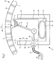
- the FIG. 2 shows a roller 8 according to the invention in a sectional plane perpendicular to the longitudinal extent L of the roller 1.
- a sealing device 9 according to the invention with the in the FIG. 1 shown sealing strip 1 installed as intended.
- the FIG. 2 shows the sealing device 9 with the sealing strip 1 in the position in which the sealing surface 3 is employed to seal an overpressure or underpressure zone, not shown, against the inner side 11 of the roll shell 10.
- the FIG. 3 shows a longitudinal end of the roll in plan view without representation of the roll shell, wherein within the roller 8 extending components are drawn with dashed lines.
- the lubricant channel 4 is connected to a supply line 12 running in sections within the sealing strip 1, which ends sealing edge side of the lubricant outlet openings 5 and by means of which lubricant 31, which is located in the lubricant channel 4 between the inner side 11 of the roll shell 10 and the sealing surface 3 can be brought.
- the sealing surface 3 and the lubricant channel 4 are arranged on the top 2, that when properly installed the sealing device 9 in the roller 8 and upon rotation of the roll shell 10 in the intended direction of rotation D, the lubricant gutter the essential part, in this case even the entire sealing surface 3 is upstream.
- the sealing strip 1 is limited in its width B by a front end face 24 and a substantially parallel rearward end face 15, between which the upper side 2 of the sealing strip 1 extends.
- the front and rear end face 24, 15 and the sealing surface 3 and the lubricant channel 4 are such arranged that in which in the FIG. 2 considered considered installation of the sealing device 9 in the roller 8 and considered when rotating the roll shell in the intended direction of rotation D, the roll shell 10 in the front end 24 on the sealing strip 1 runs first the lubricant channel 4 and then the sealing surface 3 sweeps around in the area rear end 15 of the sealing strip 1 expires.
- the sealing strip holder 25 in the present case has a holding section with two guide surfaces 26, 27 on which the sealing strip with its two sides 15, 24 of front or rear end face displaceable in the radial direction R.
- the roller 8 is slidably mounted along a path from and to the inner side 11 of the roll shell surface 10.
- the sealing strip holder 25 also has a bottom 29 on which a bellows 30 which can be filled with a pressure medium such as, for example, air is supported and by means of which the sealing strip 1 can be moved in the direction R relative to the sealing strip holder 25.
- the supply line 12 is led out of the sealing strip 1 at at least one point 28 on the rear end face 15.
- the holding section has at least one hole-shaped recess 32, through which each of the rear end face 15 of the sealing strip 1 led out portion of the supply line 12 by the sealing strip holder 25 is guided therethrough.
- the supply line 12 comprises a guided inside the sealing strip section and a guided outside of the sealing strip 1 section.
- the guided within the sealing strip 1 section of the supply line 12 comprises a extending in the longitudinal direction L of the sealing strip 1 central supply channel 13 from the several in the longitudinal direction L of the sealing strip 1 successively arranged risers 14 go out, each ending at a lubricant outlet opening 5 in the lubricant channel 4.
- From the central supply channel 13 go one or more presently guided horizontally line sections, which is guided on the rear end face 15 of the sealing strip 1 from this or are. It is conceivable that the central supply channel 13 along its longitudinal extent L has a changing cross-sectional area and / or cross-sectional geometry.
- the outside of the sealing strip 1 but within the roller 8 extending portion of the supply line 12 includes a first line section 21 and a second line section 22, as in the Figures 2 and 3 shown.
- the first line section 21 is longer than the second line section 22 and the second line section 22 is flexurally flexible compared to the first line section 21.
- the second line section 22 is formed by a braided metal tube 22.
- the second line section 22 begins within a range of a maximum of one meter calculated from the point 28 at which the supply line 12 is guided out of the sealing strip 1 and preferably has a length of 20-100cm, preferably up to 80cm.
- the first line section 21 terminates at its one longitudinal end at an example. Formed as a roller cover longitudinal side roller end 23 and at its other longitudinal end to a connecting piece 20th
- the first and the second line sections 21, 22 together form a third line section 18.
- the part of the supply line 12 running within the sealing strip 1 and a short line section extending between the central supply channel 13 and the point 28 form a fourth line section 17 fourth line section 17 is insoluble with the sealing strip. 1 connected and integral with this.
- the fourth line section 17 is here, since this is an integral part of the sealing strip 1, when removing and installing the sealing strip 1 with off or installed.
- the third and fourth line sections 18, 17 are detachably connected to one another via the connecting element 20.
Landscapes
- Engineering & Computer Science (AREA)
- General Engineering & Computer Science (AREA)
- Mechanical Engineering (AREA)
- Paper (AREA)
Claims (18)
- Rouleau (8) avec un dispositif d'étanchéité (9) destiné à assurer l'étanchéité d'une zone de surpression ou de dépression du rouleau (8) et avec une enveloppe de rouleau (10) déplaçable par rapport au dispositif d'étanchéité (9), dans lequel le dispositif d'étanchéité (9) comprend une baguette d'étanchéité (1) avec un côté supérieur (2), qui procure une face d'étanchéité (3) et une rigole à lubrifiant (4) se raccordant à la face d'étanchéité (3) et formée dans la baguette d'étanchéité (1) par au moins un creux en forme de rainure s'étendant dans la direction longitudinale de la baguette d'étanchéité (1), dans lequel la face d'étanchéité (3) et l'ouverture du creux en forme de rainure sont orientées vers le côté intérieur (11) de l'enveloppe de rouleau (10), dans lequel la rigole à lubrifiant (4) est raccordée à au moins une conduite d'alimentation (12) s'étendant au moins localement à l'intérieur de la baguette d'étanchéité (1), au moyen de laquelle du lubrifiant (31) peut être amené entre le côté intérieur (11) de l'enveloppe de rouleau (10) et la face d'étanchéité (3), dans lequel la baguette d'étanchéité (1) est limitée en longueur par deux extrémités (6.1, 6.2), caractérisé en ce que la baguette d'étanchéité (1) présente dans la région de ses deux extrémités (6.1, 6.2) respectivement une paroi (7.1, 7.2) limitant en longueur la rigole à lubrifiant (4).
- Rouleau (8) selon la revendication 1, caractérisé en ce que la rigole à lubrifiant (4) s'étend sur une partie centrale de la baguette d'étanchéité (1) et est limitée en longueur par les parois (7.1, 7.2), dans lequel la partie centrale a une longueur de plusieurs mètres et chacune des deux parois (7.1, 7.2) a une longueur de 20 cm ou moins, en particulier de 10 cm ou moins.
- Rouleau (8) selon la revendication 1 ou 2, caractérisé en ce que la conduite d'alimentation (12) comprend un canal d'alimentation central (13) s'étendant à l'intérieur de la baguette d'étanchéité (1) dans le sens de sa longueur ainsi qu'au moins une colonne montante (14) reliant l'une à l'autre la rigole à lubrifiant (4) et le canal d'alimentation central (13).
- Rouleau (8) selon la revendication 3, caractérisé en ce que le canal d'alimentation central (13) présente dans le sens de son extension longitudinale une aire de section transversale et/ou une géométrie de section transversale qui varie.
- Rouleau (8) selon au moins une des revendications précédentes, caractérisé en ce que la face d'étanchéité (3) et la rigole à lubrifiant (4) sont disposées sur le côté supérieur (2), de telle manière que, en considérant le sens de rotation prévu de l'enveloppe de rouleau (10), la rigole à lubrifiant (4) précède la partie essentielle, en particulier la totalité de la face d'étanchéité (3).
- Rouleau (8) selon au moins une des revendications précédentes, caractérisé en ce que la baguette d'étanchéité (1) est limitée en largeur par un côté frontal avant et arrière (15, 24), entre lesquels s'étend le côté supérieur (2) de la baguette d'étanchéité (1), dans lequel le côté frontal avant et arrière (15, 24) ainsi que la face d'étanchéité (3) et la rigole à lubrifiant (4) sont disposés de telle manière que, en considérant le sens de rotation prévu de l'enveloppe de rouleau (10), l'enveloppe de rouleau (10) arrive sur la baguette d'étanchéité (1) dans la région du côté frontal avant (24), franchisse d'abord la rigole à lubrifiant (4) et ensuite au moins la partie essentielle de la face d'étanchéité (3), en particulier la totalité de la face d'étanchéité (3), pour quitter la baguette d'étanchéité (1) dans la région du côté frontal arrière (15).
- Rouleau (8) selon la revendication 6, caractérisé en ce que les deux côtés sont essentiellement parallèles l'un à l'autre.
- Rouleau (8) selon la revendication 6 ou 7, caractérisé en ce que la rigole à lubrifiant (4), en la considérant dans un plan de coupe perpendiculaire à l'extension longitudinale de la baguette d'étanchéité (1), comporte un endroit le plus profond à partir duquel une paroi latérale avant s'étend en direction du côté frontal avant (24) et une paroi latérale arrière s'étend en direction de la face d'étanchéité (3), dans lequel l'arête supérieure de la paroi latérale avant jouxte le côté frontal avant (24) et l'arête supérieure de la paroi latérale arrière jouxte la face d'étanchéité (3) et dans lequel une droite reliant l'une à l'autre les deux arêtes supérieures forme avec l'horizontale un angle de 1° à 89°, en particulier un angle compris entre 15° et 80°.
- Rouleau (8) selon au moins une des revendications 6 à 8, caractérisé en ce que le dispositif d'étanchéité (9) comprend un support de baguette d'étanchéité (25) pour supporter la baguette d'étanchéité (1), dans lequel le support de baguette d'étanchéité (25) comporte une partie de maintien avec au moins une face de guidage (26, 27), sur laquelle la baguette d'étanchéité (1) est montée de façon coulissante avec au moins un des deux côtés du côté frontal avant ou arrière (15, 24), grâce à laquelle la baguette d'étanchéité (1), considérée le long d'un chemin en direction radiale du rouleau (8), peut coulisser vers le côté intérieur (11) de l'enveloppe de rouleau et inversement, dans lequel la conduite d'alimentation (12) est menée hors de la baguette d'étanchéité (1) en au moins un endroit (28) sur au moins un des deux côtés du côté frontal avant et arrière (15, 24), et dans lequel la partie de maintien présente au moins une découpe (32), à travers laquelle la partie de la conduite d'alimentation (12) menée respectivement hors dudit au moins un côté du côté frontal avant ou arrière (15, 24) de la baguette d'étanchéité (1) est guidée à travers le support de baguette d'étanchéité, et dans lequel ladite au moins une découpe (32) est configurée de telle manière que la baguette d'étanchéité (1) soit déplaçable par rapport au support de baguette d'étanchéité (25) le long du chemin de concert avec la partie de la conduite d'alimentation (12) menée à l'extérieur.
- Rouleau (8) selon la revendication 9, caractérisé en ce que ladite au moins une découpe (32) est réalisée en forme de trou ou de rainure ouverte vers le haut.
- Rouleau (8) selon l'une quelconque des revendications précédentes, caractérisé en ce que le rouleau (8) est adapté pour une machine de production ou de transformation d'une bande de matière fibreuse et la conduite d'alimentation (12) est menée hors du rouleau (8) dans la région d'au moins une extrémité de rouleau en direction longitudinale du rouleau (8).
- Rouleau (8) selon la revendication 11, caractérisé en ce que la partie de la conduite d'alimentation (12) s'étendant à l'intérieur du rouleau (8) comprend sur sa longueur guidée à l'extérieur de la baguette d'étanchéité (1) une première et une deuxième partie de conduite (21, 22), dans lequel la première partie de conduite (21) est plus longue que la deuxième partie de conduite (22) et la deuxième partie de conduite (22) est plus flexible que la première partie de conduite (21).
- Rouleau (8) selon la revendication 12, caractérisé en ce que la première partie de conduite (21) commence à ladite au moins une extrémité de rouleau (23) et s'étend dans le rouleau (8) en direction de la baguette d'étanchéité (1) et/ou la deuxième partie de conduite (22) commence dans une région d'un mètre maximum calculée à partir de l'endroit où la conduite d'alimentation (12) est menée hors de la baguette d'étanchéité (1).
- Rouleau (8) selon une des revendications 12 ou 13, caractérisé en ce que la deuxième partie de conduite flexible (22) présente une longueur comprise dans la plage de 15 cm à 200 cm, en particulier une longueur comprise dans la plage de 20 cm à 200 cm.
- Rouleau (8) selon l'une quelconque des revendications 12 à 14, caractérisé en ce que la conduite d'alimentation (12) présente une quatrième partie de conduite (17) assemblée de façon inséparable à la baguette d'étanchéité (1) ainsi qu'une troisième partie de conduite (18) assemblée de façon séparable à la quatrième partie de conduite (17), dans lequel la troisième partie de conduite (18) est formée de la première et de la deuxième parties de conduite (21, 22), et dans lequel la conduite d'alimentation (12) présente un élément d'assemblage, en particulier dans la région dudit au moins un endroit où celle-ci est menée hors de la baguette d'étanchéité (1), au moyen duquel la troisième partie de conduite (18) et la quatrième partie de conduite (17) sont assemblées l'une à l'autre de façon séparable.
- Procédé de production et/ou de transformation d'une bande de papier, de carton ou de papier ouaté avec une machine à papier, à carton ou à papier ouaté, dans lequel on guide la bande de papier, de carton ou de papier ouaté en compagnie d'une toile de machine à papier au moins localement sur au moins un rouleau (8) présentant une enveloppe de rouleau perforée (10) et au moins une zone de surpression ou de dépression, dans lequel on assure l'étanchéité de la zone de surpression ou de dépression au moyen d'un dispositif d'étanchéité (9) avec au moins une baguette d'étanchéité (1) et au moins une de ladite au moins une baguette d'étanchéité (1) comporte un côté supérieur (2) orienté vers le côté intérieur (11) de l'enveloppe de rouleau (10), lequel procure en fonctionnement d'étanchéité une face d'étanchéité (3) appliquée contre le côté intérieur (11) de l'enveloppe de rouleau (10) et au moins une ouverture de sortie de lubrifiant (5), dans lequel on introduit un lubrifiant (31) entre la face d'étanchéité (3) et le côté intérieur (11) de l'enveloppe de rouleau (10) au moyen de l'ouverture de sortie de lubrifiant (5), caractérisé en ce que l'on produit ou on transforme la bande avec une vitesse de production de 500 mètres par minute ou plus et la quantité de lubrifiant (31) utilisée par mètre de largeur de la machine et par minute est de quatre litres ou moins, en particulier de trois litres ou moins, et en particulier d'un litre ou moins.
- Procédé selon la revendication 16, caractérisé en ce que l'on utilise un rouleau (8) selon l'une quelconque des revendications 1 à 15.
- Procédé selon la revendication 16 ou 17, caractérisé en ce que le rouleau (8) est un rouleau aspirant, en particulier un rouleau aspirant coucheur dans la section de formage.
Applications Claiming Priority (2)
| Application Number | Priority Date | Filing Date | Title |
|---|---|---|---|
| DE102012214530 | 2012-08-15 | ||
| PCT/EP2013/066672 WO2014026914A1 (fr) | 2012-08-15 | 2013-08-09 | Dispositif d'étanchéité, cylindre aspirant et procédé pour la production et/ou la transformation d'une bande de papier, de carton ou de papier ouaté |
Publications (2)
| Publication Number | Publication Date |
|---|---|
| EP2885457A1 EP2885457A1 (fr) | 2015-06-24 |
| EP2885457B1 true EP2885457B1 (fr) | 2016-07-27 |
Family
ID=48953390
Family Applications (1)
| Application Number | Title | Priority Date | Filing Date |
|---|---|---|---|
| EP13747838.4A Active EP2885457B1 (fr) | 2012-08-15 | 2013-08-09 | Rouleau et procédé pour la production et/ou la transformation d'une bande de papier, de carton ou de papier ouaté |
Country Status (4)
| Country | Link |
|---|---|
| US (3) | US9650743B2 (fr) |
| EP (1) | EP2885457B1 (fr) |
| CN (1) | CN104583489B (fr) |
| WO (1) | WO2014026914A1 (fr) |
Families Citing this family (12)
| Publication number | Priority date | Publication date | Assignee | Title |
|---|---|---|---|---|
| DE102011004055A1 (de) * | 2011-02-14 | 2012-08-16 | Voith Patent Gmbh | Dichtungseinrichtung |
| DE102012208811B3 (de) * | 2012-05-25 | 2013-07-11 | Voith Patent Gmbh | Dichtleistensystem |
| US9506191B2 (en) * | 2012-08-15 | 2016-11-29 | Voith Patent Gmbh | Suction roll for a machine for producing and/or processing a paper, cardboard or tissue web |
| CN104583489B (zh) * | 2012-08-15 | 2017-03-08 | 福伊特专利有限公司 | 用于制造和/或加工纸张幅、纸板幅或棉纸幅的密封装置、吸辊和方法 |
| AT516191B1 (de) * | 2014-09-15 | 2016-08-15 | Röchling Leripa Papertech Gmbh & Co Kg | Dichtleistensysteme für Saugwalzen |
| US9834887B2 (en) | 2015-04-10 | 2017-12-05 | Coldwater Seals, Inc. | Adjustable foil apparatus for paper making machine |
| US9879377B2 (en) | 2015-04-10 | 2018-01-30 | Coldwater Seals, Inc. | Adjustable foil apparatus for paper making machine |
| DE102016218199A1 (de) * | 2016-09-22 | 2018-03-22 | Voith Patent Gmbh | Schmiereinrichtung zum Schmieren eines Bandes |
| DE102017117227A1 (de) * | 2017-07-31 | 2019-01-31 | Voith Patent Gmbh | Pressmantel und dessen Verwendung sowie Presswalze und Schuhpresse |
| DE102018105313A1 (de) * | 2018-03-08 | 2019-09-12 | Voith Patent Gmbh | Dichtleistensystem und Dichtleiste |
| WO2019238482A1 (fr) | 2018-06-11 | 2019-12-19 | Voith Patent Gmbh | Baguette d'étanchéité pour réaliser l'étanchéité d'une zone de surpression ou de dépression d'un cylindre, cylindre comprenant une telle baguette d'étanchéité et procédé de fonctionnement du cylindre |
| DE102018113831A1 (de) | 2018-06-11 | 2019-12-12 | Voith Patent Gmbh | Walze für eine Maschine zur Herstellung und/oder Verarbeitung einer Papier-, Karton- oder Tissuebahn |
Family Cites Families (26)
| Publication number | Priority date | Publication date | Assignee | Title |
|---|---|---|---|---|
| US2290777A (en) * | 1939-01-05 | 1942-07-21 | Downingtown Mfg Co | Suction box |
| US2578551A (en) * | 1948-03-05 | 1951-12-11 | Beloit Iron Works | Suction roll seal assembly |
| US2969837A (en) * | 1958-06-10 | 1961-01-31 | Layton Greenfield Inc | Suction roll construction |
| US3185618A (en) * | 1962-01-22 | 1965-05-25 | Fort Howard Paper Co | Silencers for suction rolls |
| US4076582A (en) * | 1977-04-04 | 1978-02-28 | Diamond International Corporation | Suction roll sealing strip cleaning structure |
| CH659865A5 (de) * | 1982-07-30 | 1987-02-27 | Escher Wyss Ag | Hydrostatisches stuetzelement und dessen verwendung in einer walzvorrichtung. |
| FI70952C (fi) * | 1982-10-14 | 1986-10-27 | Valmet Oy | Anordning med laong presszon vid pressbehandling av fiberbana |
| FI71369C (fi) * | 1983-03-23 | 1986-12-19 | Valmet Oy | Laongnyppress foer pappersmaskin |
| DE3408119A1 (de) * | 1984-02-06 | 1985-08-14 | Sulzer-Escher Wyss GmbH, 7980 Ravensburg | Nasspresse zum entwaessern einer faserbahn |
| SE461171C (sv) | 1988-05-25 | 1992-08-17 | Valmet Paper Machinery Inc | Press med laangt nyp foer pappers- eller kartongmaskiner |
| SE469600B (sv) * | 1991-12-23 | 1993-08-02 | Valmet Karlstad Ab | Trycksko |
| CN1153872A (zh) * | 1995-12-01 | 1997-07-09 | 沃依特·舒茨尔制纸机械公司 | 压辊 |
| DE19622018A1 (de) * | 1996-05-31 | 1997-12-04 | Voith Sulzer Papiermasch Gmbh | Schuhpresse |
| US6395137B1 (en) * | 1997-10-22 | 2002-05-28 | Valmet Corporation | Seal construction for a suction box in a suction roll in a paper/board machine |
| FI103072B (fi) | 1998-02-06 | 1999-04-15 | Valmet Corp | Paperikoneen tai paperin jälkikäsittelykoneen telan hoitopuolen päädyn liitäntä |
| DE19842837A1 (de) * | 1998-09-18 | 2000-03-23 | Voith Sulzer Papiertech Patent | Dichtungseinrichtung und Verfahren zur Abdichtung von Druckzonen in einer Papiermaschine |
| DE19842838A1 (de) * | 1998-09-18 | 2000-03-23 | Voith Sulzer Papiertech Patent | Dichtungseinrichtung und Verfahren zur Abdichtung von Druckzonen in einer Papiermaschine |
| JP2000291644A (ja) * | 1999-04-07 | 2000-10-20 | Mitsubishi Heavy Ind Ltd | ロール装置 |
| US6592721B1 (en) * | 1999-05-12 | 2003-07-15 | International Paper Company | Apparatus for dewatering a suction papermaking roll |
| JP3960974B2 (ja) * | 2003-02-17 | 2007-08-15 | メッツォ ペーパー インコーポレイテッド | サンクションロール用シールストリップ及びその製法 |
| FI119446B (fi) * | 2004-03-23 | 2008-11-14 | Metso Paper Inc | Paperi-/kartonkikoneen tai jälkikäsittelykoneen telan sisäpuolinen pitkänomainen rakenne |
| FI20055371A0 (fi) | 2005-07-01 | 2005-07-01 | Metso Paper Inc | Listaväline materiaalirainakonetta varten |
| JP4779564B2 (ja) * | 2005-10-18 | 2011-09-28 | 王子製紙株式会社 | 抄紙機のシュープレス装置及び紙の製造方法 |
| DE102011004055A1 (de) | 2011-02-14 | 2012-08-16 | Voith Patent Gmbh | Dichtungseinrichtung |
| CN104583489B (zh) * | 2012-08-15 | 2017-03-08 | 福伊特专利有限公司 | 用于制造和/或加工纸张幅、纸板幅或棉纸幅的密封装置、吸辊和方法 |
| US20150218753A1 (en) * | 2012-08-15 | 2015-08-06 | Voith Patent Gmbh | Sealing device and roller having a sealing device |
-
2013
- 2013-08-09 CN CN201380043186.2A patent/CN104583489B/zh active Active
- 2013-08-09 EP EP13747838.4A patent/EP2885457B1/fr active Active
- 2013-08-09 WO PCT/EP2013/066672 patent/WO2014026914A1/fr not_active Ceased
- 2013-08-09 US US14/421,210 patent/US9650743B2/en not_active Expired - Fee Related
-
2017
- 2017-02-15 US US15/433,565 patent/US20170159818A1/en not_active Abandoned
- 2017-09-27 US US15/716,655 patent/US10113647B2/en active Active
Also Published As
| Publication number | Publication date |
|---|---|
| US10113647B2 (en) | 2018-10-30 |
| WO2014026914A1 (fr) | 2014-02-20 |
| CN104583489B (zh) | 2017-03-08 |
| CN104583489A (zh) | 2015-04-29 |
| US20170159818A1 (en) | 2017-06-08 |
| EP2885457A1 (fr) | 2015-06-24 |
| US20150204014A1 (en) | 2015-07-23 |
| US9650743B2 (en) | 2017-05-16 |
| US20180017162A1 (en) | 2018-01-18 |
Similar Documents
| Publication | Publication Date | Title |
|---|---|---|
| EP2885457B1 (fr) | Rouleau et procédé pour la production et/ou la transformation d'une bande de papier, de carton ou de papier ouaté | |
| EP2885455B1 (fr) | Cylindre aspirant destiné à une machine pour la production et/ou la transformation d'une bande de papier, de carton ou de papier ouaté | |
| DE2916351A1 (de) | Verfahren und vorrichtung zur formierung eines mehrschichtigen strahles aus stoff zur herstellung von papier | |
| DE3101407A1 (de) | Stoffauflaufvorrichtung fuer eine papiermaschine | |
| EP2885456A1 (fr) | Baguette d'étanchéite | |
| DE1461162A1 (de) | Papiermaschine | |
| DE69115020T2 (de) | Vorrichtung zum entfernen von flüssigkeit aus dem innern eines rotierenden zylinders oder einer walze. | |
| DE2805580A1 (de) | Vorrichtung zum beschichten einer sich bewegenden bahn | |
| WO2014026869A1 (fr) | Dispositif d'étanchéité et cylindre comprenant un dispositif d'étanchéité | |
| AT14541U1 (de) | Verfahren und Anordnung beim Bahnaufführen in der Trockenpartie einer Faserbahn-Herstellungsmaschine | |
| DE602005002646T2 (de) | Vorrichtung und verfahren für eine papiermaschine | |
| DE2235847A1 (de) | Verfahren und maschine zum herstellen nicht gewebter faserstoffe aus faserigem material | |
| EP1245725B1 (fr) | Procédé et dispositif pour régler des paramètres de qualité d'une machine à papier, à tissu ou à égoutter | |
| DE102015121642A1 (de) | Formierpartie einer Faserbahnmaschine und sekundäre Formierpartie für eine Mehrlagenformierpartie einer Faserbahnmaschine | |
| DE69523257T2 (de) | Doppelsiebformer in einer papiermaschine | |
| DE102007058728A1 (de) | Anordnung und Verfahren zur Stabilisierung der Bahn in einer Papier- oder Kartonmaschine | |
| EP1953296B1 (fr) | Procédé de fabrication d'une bande de matière fibreuse et section de formage à deux toiles pour la mise en oeuvre du procédé | |
| EP3802950B1 (fr) | Baguette d'étanchéité pour réaliser l'étanchéité d'une zone de surpression ou de dépression d'un cylindre, cylindre comprenant une telle baguette d'étanchéité et procédés de fonctionnement du cylindre | |
| EP3802951B1 (fr) | Rouleau pour machine de fabrication et/ou de traitement d'une bande de papier, de carton ou de tissu, et procédé d'utilisation du rouleau | |
| DE212010000109U1 (de) | Schabervorrichtung für eine Faserbahnmaschine und Schaberanordnung in einer Faserbahnmaschine | |
| DE10154862A1 (de) | Vorrichtung zum Abführen von Flüssigkeit | |
| DE102022121105A1 (de) | Schrägsiebformer | |
| DE112009000825T5 (de) | Vorrichtung und Verfahren zum Zuführen von Faserpulpe zu einer Bahnbildungseinrichtung | |
| DE1150864B (de) | Hochdruckstoffauflauf fuer Papiermaschinen | |
| DE202004001935U1 (de) | Blattbildungssystem |
Legal Events
| Date | Code | Title | Description |
|---|---|---|---|
| PUAI | Public reference made under article 153(3) epc to a published international application that has entered the european phase |
Free format text: ORIGINAL CODE: 0009012 |
|
| 17P | Request for examination filed |
Effective date: 20150316 |
|
| AK | Designated contracting states |
Kind code of ref document: A1 Designated state(s): AL AT BE BG CH CY CZ DE DK EE ES FI FR GB GR HR HU IE IS IT LI LT LU LV MC MK MT NL NO PL PT RO RS SE SI SK SM TR |
|
| AX | Request for extension of the european patent |
Extension state: BA ME |
|
| RIN1 | Information on inventor provided before grant (corrected) |
Inventor name: HONOLD, JOCHEN Inventor name: ERKELENZ, MARCH |
|
| DAX | Request for extension of the european patent (deleted) | ||
| GRAP | Despatch of communication of intention to grant a patent |
Free format text: ORIGINAL CODE: EPIDOSNIGR1 |
|
| INTG | Intention to grant announced |
Effective date: 20160216 |
|
| GRAS | Grant fee paid |
Free format text: ORIGINAL CODE: EPIDOSNIGR3 |
|
| GRAA | (expected) grant |
Free format text: ORIGINAL CODE: 0009210 |
|
| AK | Designated contracting states |
Kind code of ref document: B1 Designated state(s): AL AT BE BG CH CY CZ DE DK EE ES FI FR GB GR HR HU IE IS IT LI LT LU LV MC MK MT NL NO PL PT RO RS SE SI SK SM TR |
|
| REG | Reference to a national code |
Ref country code: GB Ref legal event code: FG4D Free format text: NOT ENGLISH |
|
| REG | Reference to a national code |
Ref country code: CH Ref legal event code: EP |
|
| REG | Reference to a national code |
Ref country code: AT Ref legal event code: REF Ref document number: 815899 Country of ref document: AT Kind code of ref document: T Effective date: 20160815 |
|
| REG | Reference to a national code |
Ref country code: IE Ref legal event code: FG4D Free format text: LANGUAGE OF EP DOCUMENT: GERMAN |
|
| REG | Reference to a national code |
Ref country code: DE Ref legal event code: R096 Ref document number: 502013003896 Country of ref document: DE |
|
| REG | Reference to a national code |
Ref country code: SE Ref legal event code: TRGR |
|
| REG | Reference to a national code |
Ref country code: LT Ref legal event code: MG4D |
|
| REG | Reference to a national code |
Ref country code: NL Ref legal event code: MP Effective date: 20160727 |
|
| PG25 | Lapsed in a contracting state [announced via postgrant information from national office to epo] |
Ref country code: BE Free format text: LAPSE BECAUSE OF NON-PAYMENT OF DUE FEES Effective date: 20160831 |
|
| PG25 | Lapsed in a contracting state [announced via postgrant information from national office to epo] |
Ref country code: IS Free format text: LAPSE BECAUSE OF FAILURE TO SUBMIT A TRANSLATION OF THE DESCRIPTION OR TO PAY THE FEE WITHIN THE PRESCRIBED TIME-LIMIT Effective date: 20161127 Ref country code: NO Free format text: LAPSE BECAUSE OF FAILURE TO SUBMIT A TRANSLATION OF THE DESCRIPTION OR TO PAY THE FEE WITHIN THE PRESCRIBED TIME-LIMIT Effective date: 20161027 Ref country code: IT Free format text: LAPSE BECAUSE OF FAILURE TO SUBMIT A TRANSLATION OF THE DESCRIPTION OR TO PAY THE FEE WITHIN THE PRESCRIBED TIME-LIMIT Effective date: 20160727 Ref country code: HR Free format text: LAPSE BECAUSE OF FAILURE TO SUBMIT A TRANSLATION OF THE DESCRIPTION OR TO PAY THE FEE WITHIN THE PRESCRIBED TIME-LIMIT Effective date: 20160727 Ref country code: NL Free format text: LAPSE BECAUSE OF FAILURE TO SUBMIT A TRANSLATION OF THE DESCRIPTION OR TO PAY THE FEE WITHIN THE PRESCRIBED TIME-LIMIT Effective date: 20160727 Ref country code: LT Free format text: LAPSE BECAUSE OF FAILURE TO SUBMIT A TRANSLATION OF THE DESCRIPTION OR TO PAY THE FEE WITHIN THE PRESCRIBED TIME-LIMIT Effective date: 20160727 Ref country code: RS Free format text: LAPSE BECAUSE OF FAILURE TO SUBMIT A TRANSLATION OF THE DESCRIPTION OR TO PAY THE FEE WITHIN THE PRESCRIBED TIME-LIMIT Effective date: 20160727 |
|
| PG25 | Lapsed in a contracting state [announced via postgrant information from national office to epo] |
Ref country code: GR Free format text: LAPSE BECAUSE OF FAILURE TO SUBMIT A TRANSLATION OF THE DESCRIPTION OR TO PAY THE FEE WITHIN THE PRESCRIBED TIME-LIMIT Effective date: 20161028 Ref country code: LV Free format text: LAPSE BECAUSE OF FAILURE TO SUBMIT A TRANSLATION OF THE DESCRIPTION OR TO PAY THE FEE WITHIN THE PRESCRIBED TIME-LIMIT Effective date: 20160727 Ref country code: PT Free format text: LAPSE BECAUSE OF FAILURE TO SUBMIT A TRANSLATION OF THE DESCRIPTION OR TO PAY THE FEE WITHIN THE PRESCRIBED TIME-LIMIT Effective date: 20161128 Ref country code: PL Free format text: LAPSE BECAUSE OF FAILURE TO SUBMIT A TRANSLATION OF THE DESCRIPTION OR TO PAY THE FEE WITHIN THE PRESCRIBED TIME-LIMIT Effective date: 20160727 Ref country code: ES Free format text: LAPSE BECAUSE OF FAILURE TO SUBMIT A TRANSLATION OF THE DESCRIPTION OR TO PAY THE FEE WITHIN THE PRESCRIBED TIME-LIMIT Effective date: 20160727 |
|
| REG | Reference to a national code |
Ref country code: CH Ref legal event code: PL |
|
| PG25 | Lapsed in a contracting state [announced via postgrant information from national office to epo] |
Ref country code: LI Free format text: LAPSE BECAUSE OF NON-PAYMENT OF DUE FEES Effective date: 20160831 Ref country code: EE Free format text: LAPSE BECAUSE OF FAILURE TO SUBMIT A TRANSLATION OF THE DESCRIPTION OR TO PAY THE FEE WITHIN THE PRESCRIBED TIME-LIMIT Effective date: 20160727 Ref country code: CH Free format text: LAPSE BECAUSE OF NON-PAYMENT OF DUE FEES Effective date: 20160831 Ref country code: RO Free format text: LAPSE BECAUSE OF FAILURE TO SUBMIT A TRANSLATION OF THE DESCRIPTION OR TO PAY THE FEE WITHIN THE PRESCRIBED TIME-LIMIT Effective date: 20160727 Ref country code: MC Free format text: LAPSE BECAUSE OF FAILURE TO SUBMIT A TRANSLATION OF THE DESCRIPTION OR TO PAY THE FEE WITHIN THE PRESCRIBED TIME-LIMIT Effective date: 20160727 |
|
| REG | Reference to a national code |
Ref country code: DE Ref legal event code: R097 Ref document number: 502013003896 Country of ref document: DE |
|
| PG25 | Lapsed in a contracting state [announced via postgrant information from national office to epo] |
Ref country code: DK Free format text: LAPSE BECAUSE OF FAILURE TO SUBMIT A TRANSLATION OF THE DESCRIPTION OR TO PAY THE FEE WITHIN THE PRESCRIBED TIME-LIMIT Effective date: 20160727 Ref country code: CZ Free format text: LAPSE BECAUSE OF FAILURE TO SUBMIT A TRANSLATION OF THE DESCRIPTION OR TO PAY THE FEE WITHIN THE PRESCRIBED TIME-LIMIT Effective date: 20160727 Ref country code: SM Free format text: LAPSE BECAUSE OF FAILURE TO SUBMIT A TRANSLATION OF THE DESCRIPTION OR TO PAY THE FEE WITHIN THE PRESCRIBED TIME-LIMIT Effective date: 20160727 Ref country code: SK Free format text: LAPSE BECAUSE OF FAILURE TO SUBMIT A TRANSLATION OF THE DESCRIPTION OR TO PAY THE FEE WITHIN THE PRESCRIBED TIME-LIMIT Effective date: 20160727 Ref country code: BG Free format text: LAPSE BECAUSE OF FAILURE TO SUBMIT A TRANSLATION OF THE DESCRIPTION OR TO PAY THE FEE WITHIN THE PRESCRIBED TIME-LIMIT Effective date: 20161027 |
|
| REG | Reference to a national code |
Ref country code: IE Ref legal event code: MM4A |
|
| PLBE | No opposition filed within time limit |
Free format text: ORIGINAL CODE: 0009261 |
|
| STAA | Information on the status of an ep patent application or granted ep patent |
Free format text: STATUS: NO OPPOSITION FILED WITHIN TIME LIMIT |
|
| 26N | No opposition filed |
Effective date: 20170502 |
|
| REG | Reference to a national code |
Ref country code: FR Ref legal event code: ST Effective date: 20170609 |
|
| PG25 | Lapsed in a contracting state [announced via postgrant information from national office to epo] |
Ref country code: FR Free format text: LAPSE BECAUSE OF NON-PAYMENT OF DUE FEES Effective date: 20160927 Ref country code: IE Free format text: LAPSE BECAUSE OF NON-PAYMENT OF DUE FEES Effective date: 20160809 |
|
| PG25 | Lapsed in a contracting state [announced via postgrant information from national office to epo] |
Ref country code: SI Free format text: LAPSE BECAUSE OF FAILURE TO SUBMIT A TRANSLATION OF THE DESCRIPTION OR TO PAY THE FEE WITHIN THE PRESCRIBED TIME-LIMIT Effective date: 20160727 Ref country code: LU Free format text: LAPSE BECAUSE OF NON-PAYMENT OF DUE FEES Effective date: 20160809 |
|
| GBPC | Gb: european patent ceased through non-payment of renewal fee |
Effective date: 20170809 |
|
| PG25 | Lapsed in a contracting state [announced via postgrant information from national office to epo] |
Ref country code: HU Free format text: LAPSE BECAUSE OF FAILURE TO SUBMIT A TRANSLATION OF THE DESCRIPTION OR TO PAY THE FEE WITHIN THE PRESCRIBED TIME-LIMIT; INVALID AB INITIO Effective date: 20130809 |
|
| PG25 | Lapsed in a contracting state [announced via postgrant information from national office to epo] |
Ref country code: CY Free format text: LAPSE BECAUSE OF FAILURE TO SUBMIT A TRANSLATION OF THE DESCRIPTION OR TO PAY THE FEE WITHIN THE PRESCRIBED TIME-LIMIT Effective date: 20160727 Ref country code: MT Free format text: LAPSE BECAUSE OF FAILURE TO SUBMIT A TRANSLATION OF THE DESCRIPTION OR TO PAY THE FEE WITHIN THE PRESCRIBED TIME-LIMIT Effective date: 20160727 Ref country code: MK Free format text: LAPSE BECAUSE OF FAILURE TO SUBMIT A TRANSLATION OF THE DESCRIPTION OR TO PAY THE FEE WITHIN THE PRESCRIBED TIME-LIMIT Effective date: 20160727 |
|
| PG25 | Lapsed in a contracting state [announced via postgrant information from national office to epo] |
Ref country code: GB Free format text: LAPSE BECAUSE OF NON-PAYMENT OF DUE FEES Effective date: 20170809 |
|
| PG25 | Lapsed in a contracting state [announced via postgrant information from national office to epo] |
Ref country code: AL Free format text: LAPSE BECAUSE OF FAILURE TO SUBMIT A TRANSLATION OF THE DESCRIPTION OR TO PAY THE FEE WITHIN THE PRESCRIBED TIME-LIMIT Effective date: 20160727 Ref country code: TR Free format text: LAPSE BECAUSE OF FAILURE TO SUBMIT A TRANSLATION OF THE DESCRIPTION OR TO PAY THE FEE WITHIN THE PRESCRIBED TIME-LIMIT Effective date: 20160727 |
|
| PGFP | Annual fee paid to national office [announced via postgrant information from national office to epo] |
Ref country code: FI Payment date: 20250822 Year of fee payment: 13 |
|
| PGFP | Annual fee paid to national office [announced via postgrant information from national office to epo] |
Ref country code: DE Payment date: 20250820 Year of fee payment: 13 |
|
| PGFP | Annual fee paid to national office [announced via postgrant information from national office to epo] |
Ref country code: AT Payment date: 20250821 Year of fee payment: 13 |
|
| PGFP | Annual fee paid to national office [announced via postgrant information from national office to epo] |
Ref country code: SE Payment date: 20250820 Year of fee payment: 13 |