EP2885502B1 - Ensemble moteur de ventilateur soufflant ayant une surface d'orientation d'air - Google Patents
Ensemble moteur de ventilateur soufflant ayant une surface d'orientation d'air Download PDFInfo
- Publication number
- EP2885502B1 EP2885502B1 EP13820440.9A EP13820440A EP2885502B1 EP 2885502 B1 EP2885502 B1 EP 2885502B1 EP 13820440 A EP13820440 A EP 13820440A EP 2885502 B1 EP2885502 B1 EP 2885502B1
- Authority
- EP
- European Patent Office
- Prior art keywords
- directing surface
- air directing
- diameter
- air
- region
- Prior art date
- Legal status (The legal status is an assumption and is not a legal conclusion. Google has not performed a legal analysis and makes no representation as to the accuracy of the status listed.)
- Not-in-force
Links
- 230000004907 flux Effects 0.000 description 5
- 238000000429 assembly Methods 0.000 description 2
- 230000000712 assembly Effects 0.000 description 2
- 238000002474 experimental method Methods 0.000 description 2
- 238000011144 upstream manufacturing Methods 0.000 description 2
- 238000004378 air conditioning Methods 0.000 description 1
- 238000010276 construction Methods 0.000 description 1
- 230000001419 dependent effect Effects 0.000 description 1
- 230000000694 effects Effects 0.000 description 1
- 238000012986 modification Methods 0.000 description 1
- 230000004048 modification Effects 0.000 description 1
- 230000003068 static effect Effects 0.000 description 1
- 238000009423 ventilation Methods 0.000 description 1
Images


Classifications
-
- F—MECHANICAL ENGINEERING; LIGHTING; HEATING; WEAPONS; BLASTING
- F04—POSITIVE - DISPLACEMENT MACHINES FOR LIQUIDS; PUMPS FOR LIQUIDS OR ELASTIC FLUIDS
- F04D—NON-POSITIVE-DISPLACEMENT PUMPS
- F04D25/00—Pumping installations or systems
- F04D25/02—Units comprising pumps and their driving means
- F04D25/06—Units comprising pumps and their driving means the pump being electrically driven
- F04D25/068—Mechanical details of the pump control unit
-
- F—MECHANICAL ENGINEERING; LIGHTING; HEATING; WEAPONS; BLASTING
- F04—POSITIVE - DISPLACEMENT MACHINES FOR LIQUIDS; PUMPS FOR LIQUIDS OR ELASTIC FLUIDS
- F04D—NON-POSITIVE-DISPLACEMENT PUMPS
- F04D25/00—Pumping installations or systems
- F04D25/02—Units comprising pumps and their driving means
- F04D25/06—Units comprising pumps and their driving means the pump being electrically driven
- F04D25/0606—Units comprising pumps and their driving means the pump being electrically driven the electric motor being specially adapted for integration in the pump
- F04D25/0653—Units comprising pumps and their driving means the pump being electrically driven the electric motor being specially adapted for integration in the pump the motor having a plane air gap, e.g. disc-type
-
- F—MECHANICAL ENGINEERING; LIGHTING; HEATING; WEAPONS; BLASTING
- F04—POSITIVE - DISPLACEMENT MACHINES FOR LIQUIDS; PUMPS FOR LIQUIDS OR ELASTIC FLUIDS
- F04D—NON-POSITIVE-DISPLACEMENT PUMPS
- F04D29/00—Details, component parts, or accessories
- F04D29/40—Casings; Connections of working fluid
- F04D29/42—Casings; Connections of working fluid for radial or helico-centrifugal pumps
- F04D29/4206—Casings; Connections of working fluid for radial or helico-centrifugal pumps especially adapted for elastic fluid pumps
- F04D29/4213—Casings; Connections of working fluid for radial or helico-centrifugal pumps especially adapted for elastic fluid pumps suction ports
-
- F—MECHANICAL ENGINEERING; LIGHTING; HEATING; WEAPONS; BLASTING
- F04—POSITIVE - DISPLACEMENT MACHINES FOR LIQUIDS; PUMPS FOR LIQUIDS OR ELASTIC FLUIDS
- F04D—NON-POSITIVE-DISPLACEMENT PUMPS
- F04D29/00—Details, component parts, or accessories
- F04D29/58—Cooling; Heating; Diminishing heat transfer
- F04D29/5813—Cooling the control unit
Definitions
- Document GB 2 260 576 A relates to an indoor unit of a ventilation system, a ventilator and an air conditioner.
- Document EP 1 536 142 A1 pertains to a motor-blower unit.
- Document JP 2005 291050 A discloses a centrifugal fan.
- Document FR 2 772 437 A1 discloses an air fan for an air conditioning system of a vehicle.
- a blower assembly as known from EP1536142 includes a motor assembly covered by an air directing surface of the rotor of this unit. The axis of the motor is not included in the air directing surface.
- the present invention relates to a blower assembly according to claim 1.
- Preferred embodiments are detailed in the dependent claims.
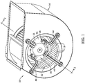
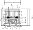
- a blower assembly in accordance with the invention is generally represented by the numeral 10 as shown in Figures 1 and 2 .
- the blower assembly comprises a centrifugal fan, generally indicated at 12, a motor assembly, generally indicated at 14, and a blower housing, generally indicated at 16.
- the centrifugal fan 12 is rotatable about a fan axis X.
- the centrifugal fan 12 has a plurality of axially extending impeller blades 18, a first axial end 20, a second axial end 22 opposite the first axial end, a first air inlet 24, and a second air inlet 26.
- the first air inlet 24 is at the first axial end 20 of the centrifugal fan 12.
- the second air inlet 26 is at the second axial end 22 of the centrifugal fan 12.
- the impeller blades 18 have inner surfaces 28 that combine to define a fan inner diameter d f .
- the centrifugal fan 12 is journaled to the blower housing 16, preferably in any conventional manner, for rotation of the centrifugal fan relative to the blower housing about the fan axis X.
- the motor assembly 14 comprises a stator 30, a rotor 32, an air deflector member 34 and an air directing surface 36.
- the motor assembly 14 comprises an axial flux motor, and comprises an electronically commutated motor.
- the motor assembly 14 may be entirely contained within the centrifugal fan 12.
- the rotor 32 is configured to rotate relative to the stator 30 for rotation about a rotor axis.
- the centrifugal fan is coupled to the rotor in a manner such that the centrifugal fan rotates with the rotor about the rotor axis, and preferably in a direct drive manner.
- the rotor axis is the same axis as the fan axis X.
- the reference X applies equally to the rotor axis and the fan axis.
- the blower housing 16 includes first and second housing air inlets 38, 40.
- the first housing air inlet 38 is generally adjacent the first air inlet 24 of the centrifugal fan 12.
- the second housing air inlet 40 is generally adjacent the second air inlet 26 of the centrifugal fan 12. As shown in Figures 1 and 2 , the centrifugal fan may be entirely contained within the blower housing 16.
- the blower assembly 10 further comprises a motor support bracket, generally indicated at 42.
- the motor support bracket 42 operatively secures the air deflector member 34 to the blower housing 16.
- the motor support bracket 42 operatively secures the motor assembly 14 to the blower housing 16 via the air deflector member 34.
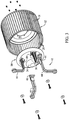
- the motor support bracket 42 includes a plurality of leg members 44, but it is to be understood that other types of brackets could be employed without departing from the scope of this invention.
- Each leg member 44 includes a foot portion 46. Each foot portion 46 is within a corresponding foot receiving recess 48 in the air deflector member 34.
- the air directing surface 36 is operatively coupled to the stator 30 such that the air directing surface 36 remains stationary relative to the stator 30 as the rotor 32 and centrifugal fan 12 are rotated relative to the stator 30 about the rotor axis X.
- the air directing surface 36 of the motor assembly 14 is shaped and configured to direct air drawn into the first air inlet 24 radially outwardly toward the impeller blades 18.
- the air directing surface 36 has a first end 50 and a second end 52.
- the air directing surface 36 extends generally along the rotor axis X from the first end 50 to the second end 52.
- At least a surface region 54 of the air directing surface 36 generally circumscribes the rotor axis X and diverges radially outwardly as such surface region 54 of the air directing surface 36 extends away from the first end 50 of the air directing surface 36 and toward the second end 52 of the air directing surface 36.
- a surface of the air deflector member 34 comprises at least a portion of the surface region 54 of the air directing surface 36.
- the surface region 54 of the air directing surface 36 is axially aligned with portions of the impeller blades 18 (see Figure 2 ) such that said surface region 54 of the air directing surface 36 is surrounded by said portions of the impeller blades 18.
- the first end 50 of the air directing surface 36 has a diameter d 1 and the second end 52 of the air directing surface 36 has a diameter d 2 .
- the axial distance X 1-2 ( Figure 2 )between the first and second ends 50, 52 of the air directing surface 36 is preferably at least 25% of the diameter d 2 of the second end 52 of the air directing surface 36, and is more preferably at least 33% of the diameter d 2 .
- the diameter d 1 of the first end 50 of the air directing surface 36 is preferably less than 50% of the diameter d 2 of the second end 52 of the air directing surface 36, and more preferably is less than 40% of the diameter d 2 , and more preferably is less than 30% of the diameter d 2 , and more preferably is less than 20% of the diameter d 2 , and more preferably is less than 10% of the diameter d 2 .
- the diameter d 2 of the second end 52 of the air directing surface 36 is preferably at least 50% of the fan inner diameter d f , and is more preferably at least 60% of the fan inner diameter d f , and is more preferably at least 70% of the fan inner diameter d f , and is more preferably at least 75% of the fan inner diameter d f .
- the air directing surface 36 includes a mid-region which is generally midway axially between the first and second ends of the air directing surface 36, the mid-region of the air directing surface 36 having a diameter d m .
- the diameter d m of the mid-region of the air directing surface 36 is less than 80% of the diameter d 2 of the second end 52 of the air directing surface 36.
- the diameter d 1 of the first end 50 of the air directing surface 36 is preferably less than 70% of the diameter d m of the mid-region of the air directing surface 36, and is more preferably less than 50% of the diameter d m of the mid-region of the air directing surface 36, and is more preferably less than 40% of the diameter d m of the mid-region of the air directing surface 36.
- the surface region 54 of the air directing surface 36 has a generally circular cross section in a plane perpendicular to the rotor axis X.
- the air directing surface 36 of this embodiment comprises a conic section, and preferably a conic section of a right, circular cone.
- the surface region 54 of the air directing surface 36 may have other shapes without departing from the scope of the invention.
- an alternative surface region of an air directing surface may have a polygonal cross section (e.g., a substantially equilateral polygon of six or more sides) in a plane perpendicular to the rotor axis.
- the air directing surface 36 of the preferred embodiment includes a nose region 56.
- the nose region 56 extends (i.e., projects) axially from the first end 50 of the air directing surface 36 toward the second end 52 of the air directing surface 36.
- the nose region 56 diverges as it extends axially from the first end 50 toward the second end 52.
- the nose region has a curved cross section in a cross-sectional plane that includes the rotor axis.
- the nose region could alternatively be pointed or blunted without departing from the scope of the invention.
- the air directing surface 36 may comprise surface portions of a plurality of parts.
- the nose region 56 may be an outer surface of a nose piece.
- the air directing surface 36 diverges substantially continuously from the mid-region of the air directing surface 36 to the second end 52 of the air directing surface 36.
- the air directing surface 36 preferably diverges generally from its first end 50 toward its second end 52, and more preferably diverges generally from its first end 50 to its second end 52. In the embodiment shown in Figures 1-3 , the air directing surface 36 diverges generally continuously from the first end 50 of the air directing surface 36 to the second end 52 of the air directing surface 36.
- the air directing surface 36 converges generally from its second end 2 toward the first end 50, but an end margin of the air directing surface 36 could have a non-diverging region without departing from the scope of the invention.
- the second end 52 of the air directing surface 36 generally circumscribes a portion of the rotor 32, and at least a portion of the rotor 32 is axially between the first and second ends 50, 52 of the air directing surface 36 and surrounded by the air directing surface 36.
- the stator 30 is axially between the first and second ends 50, 52 of the air directing surface 36 and surrounded by the air directing surface 36.
- the centrifugal fan 12 may include a drive plate 58 between the first and second axial ends 20, 22 of the centrifugal fan, with the rotor 32 of the motor assembly 14 being operatively coupled to drive plate 58 of the centrifugal fan.
- the second end 52 of the air directing surface 36 may be generally adjacent the drive plate 58.
- the drive plate 58 may be located substantially midway between the first and second axial ends 20, 22 of the centrifugal fan 12, but may alternatively be closer to one of the first and second axial ends.
- the drive plate 58 may be generally annular in shape.
- the motor assembly 14 of the present embodiment further includes at least one electronic component 60 ( Figure 2 ) adapted and configured to control a function of the motor assembly.
- the electronic component 60 may be surrounded by the air directing surface 36.
- the electronic component 60 may be positioned relative to the air directing surface 36 such that at least 75% by volume of the electronic component 60 is axially between the first and second ends of the air directing surface 36 and surrounded by the air directing surface 36.
- the at least one electronic component 60 may comprise a plurality of electronic components 60a, 60b adapted and configured to control the motor assembly.
- the plurality of electronic components may be positioned relative to the air directing surface 36 such that at least 75% by volume of said plurality of electronic components is axially between the first and second ends 50, 52 of the air directing surface 36 and surrounded by the air directing surface 36.
- the blower assembly 10 will be employed in a conduit, such as a conduit of an HVAC system.
- the air directing surface 36 is shaped and configured such that to produce a given flow and pressure within a conduit, the air directing surface 36 reduces the energy required to power the blower assembly by at least 5% (and by at least 10%) over the energy required to power a second blower assembly (not shown) that is identical to the blower assembly 14 with the exception that the second blower assembly is devoid of an air directing surface 36.
- the motor assembly of the second blower assembly is a typical cylindrically shaped motor assembly.
- the blower assembly 10 is shown in a test conduit 80.
- the test conduit 80 has first and second planar surfaces 82, 84 perpendicular to the rotor axis X with the first planar surface 82 of the conduit spaced three inches from the first housing air inlet 38 such that air upstream of the first housing air inlet 38 is drawn radially inwardly into the first housing air inlet 38, and with the second planar surface 84 of the conduit 80 spaced three inches from the second housing air inlet 40 such that air upstream of the second housing air inlet 40 is drawn radially inwardly into the second housing air inlet 40.
- the air deflector member 34 is shaped and configured such that to produce a given exhaust flow (e.g., 1450 cfm) and pressure (e.g., 0.5 in-wc) of the first blower assembly 10 when the first blower assembly 10 is in the test conduit 80, the air deflector member 34 reduces the energy required to power the blower assembly 10 by at least 5% (and by at least 10%) over the energy required to power a second blower assembly that is identical to the first blower assembly and in an identical conduit with the exception that the second blower assembly is devoid of an air deflector member 34.
- a given exhaust flow e.g., 1450 cfm
- pressure e.g., 0.5 in-wc
- blower/motor Assembly A a standard cylindrically-shaped motor coupled to a blower having a 10-10 impeller
- Blower/Motor Assembly B a motor assembly having an air deflector member and coupled to a blower having a 10-10 impeller
- the presence of the air deflector member results in substantially higher blower efficiencies.
- Figure 6 shows an alternative blower assembly 110 with a motor assembly 114.
- the motor assembly 114 is essentially the same as the motor assembly 14 of Figures 1-3 , except the motor assembly 114 includes a radial flux motor instead of an axial flux motor.
- the description above with respect to the embodiment of Figures 1-3 applies also the embodiment of Figure 6 .
- a further description of the embodiment of Figure 6 is unnecessary.
Landscapes
- Engineering & Computer Science (AREA)
- Mechanical Engineering (AREA)
- General Engineering & Computer Science (AREA)
- Physics & Mathematics (AREA)
- Thermal Sciences (AREA)
- Structures Of Non-Positive Displacement Pumps (AREA)
Claims (15)
- Un ensemble de souffleur (10) comprenant :
un ventilateur centrifuge (12) pivotant autour d'un axe de ventilateur (X), le ventilateur centrifuge ayant plusieurs aubes se prolongeant de manière axiale (18), une première extrémité axiale (20) et une admission d'air (24), l'admission d'air se trouvant sur la première extrémité axiale du ventilateur centrifuge, les aubes (18) présentant des surfaces internes qui se combinent pour définir un diamètre interne de ventilateur df :un ensemble de moteur (14) comprenant un stator (30), un rotor (32) et une surface de diffusion d'air (36), l'ensemble de moteur (14) entièrement contenu dans le ventilateur centrifuge (12), le rotor étant configuré pour tourner par rapport au stator autour d'un axe de rotor, le ventilateur centrifuge (12) étant couplé au rotor de sorte que le ventilateur centrifuge tourne avec le rotor autour de l'axe du rotor, la surface de diffusion d'air (36) étant façonnée et configurée pour diriger l'air aspiré dans l'admission d'air de manière radiale vers l'extérieur en direction des aubes (18), la surface de diffusion d'air (36) étant stationnaire par rapport au stator et présentant une première extrémité (50) et une seconde extrémité (52).une partie du rotor (32) et le stator (30) étant situés entre la première extrémité (50) et la seconde extrémité (52) de la surface de diffusion d'air (36) et entourés par la surface de diffusion d'air (36), la surface de diffusion d'air (36) se prolongeant généralement le long de l'axe du rotor de la première extrémité à la seconde extrémité, au moins une région de surface (54) de la surface de diffusion d'air entourant généralement l'axe du rotor et divergent de manière radiale vers l'extérieur lorsque ladite région de surface de la surface de diffusion d'air s'éloigne de la première extrémité de la surface de diffusion d'air et vers la seconde extrémité de la surface de diffusion d'air, la surface de diffusion d'air (54) ayant une région nasale (56), ladite région nasale se prolongeant de manière axiale de la première extrémité de la surface de diffusion d'air vers la seconde extrémité de la surface de diffusion d'air, ladite région nasale (56) présentant une section transversale dans un plan tranversal qui inclut l'axe du rotor, ladite région de surface (54) de la surface de diffusion d'air étant alignée de manière axiale avec les parties des aubes (18) de sorte que ladite région de surface de la surface de diffusion d'air est entourée par lesdites parties des aubes. - Un ensemble de souffleur selon la revendication 1, dans lequel la surface de diffusion d'air (36) est couplée de manière opérationnelle avec le stator (30) de sorte que la surface de diffusion d'air demeure stationnaire par rapport au stator lorsque le rotor (32) et le ventilateur centrifuge tournent par rapport au stator autour de l'axe du rotor.
- Un ensemble de souffleur (10) selon la revendication 1, dans lequel la première extrémité (50) de la surface de diffusion d'air présente un diamètre d1 et la seconde extrémité (52) de la surface de diffusion d'air présente un diamètre d2 et dans lequel le diamètre d1 est inférieur à 50 % au diamètre d2 et dans lequel le diamètre d2 est au moins égal à 50 % du diamètre interne du ventilateur d1.
- Un ensemble de souffleur (10) selon la revendication 3, dans lequel la surface de diffusion d'air (36) comprend une région intermédiaire qui est généralement à mi-chemin de manière axiale entre la première et la seconde extrémité de la surface de diffusion d'air, la région intermédiaire de la surface de diffusion d'air présentant un diamètre dm, le diamètre dm, est inférieur à 80 % du diamètre d2, le diamètre d1 est inférieur à 70 % du diamètre dm.
- Un ensemble de souffleur (10) selon la revendication 4, dans lequel le diamètre d1 est inférieur à 40 % du diamètre d2.
- Un ensemble de souffleur (10) selon la revendication 4, dans lequel le diamètre d1 est inférieur à 20 % du diamètre d2.
- Un ensemble de souffleur (10) selon la revendication 4, dans lequel le diamètre d2 est d'au moins 70 % du diamètre interne du ventilateur d1.
- Un ensemble de souffleur (10) selon la revendication 4, dans lequel le diamètre d1 est inférieur à 50 % du diamètre dm.
- Un ensemble de souffleur (10) selon la revendication 8, dans lequel la surface de diffusion d'air diverge en continu de la région intermédiaire de la surface de diffusion d'air (36) vers la seconde extrémité de la surface de diffusion d'air.
- Un ensemble de souffleur (10) selon la revendication 3, dans lequel la surface de diffusion d'air (36) comprend une région intermédiaire qui se trouve généralement à mi-chemin de manière axiale entre la première et la seconde extrémité de la surface de diffusion d'air, la région intermédiaire de la surface de diffusion d'air ayant un diamètre dm, le diamètre dm est inférieur à 60 % du diamètre d2, le diamètre d1 est inférieur à 50 % du diamètre dm.
- Un ensemble de souffleur (10) selon la revendication 1, dans lequel la région nasale présente une section transversale incurvée dans un plan tranversal qui comprend l'axe du rotor (X).
- Un ensemble de souffleur (10) selon la revendication 11, dans lequel la surface de diffusion d'air (36) diverge de manière substantielle et continue de la région nasale (56) de la surface de diffusion d'air vers la seconde extrémité de la surface de diffusion d'air.
- Un ensemble de souffleur (10) selon la revendication 1, dans lequel la surface de diffusion d'air (36) converge de la seconde extrémité vers la première extrémité.
- Un ensemble de souffleur (10) selon la revendication 1, dans lequel la seconde extrémité de la surface de diffusion d'air (36) entoure généralement une partie du rotor.
- (Annulé).
Applications Claiming Priority (3)
| Application Number | Priority Date | Filing Date | Title |
|---|---|---|---|
| US201261674099P | 2012-07-20 | 2012-07-20 | |
| US13/627,587 US9777735B2 (en) | 2012-07-20 | 2012-09-26 | Blower motor assembly having air directing surface |
| PCT/US2013/046605 WO2014014609A1 (fr) | 2012-07-20 | 2013-06-19 | Ensemble moteur de ventilateur soufflant ayant une surface d'orientation d'air |
Publications (3)
| Publication Number | Publication Date |
|---|---|
| EP2885502A1 EP2885502A1 (fr) | 2015-06-24 |
| EP2885502A4 EP2885502A4 (fr) | 2016-05-11 |
| EP2885502B1 true EP2885502B1 (fr) | 2021-03-10 |
Family
ID=49946701
Family Applications (1)
| Application Number | Title | Priority Date | Filing Date |
|---|---|---|---|
| EP13820440.9A Not-in-force EP2885502B1 (fr) | 2012-07-20 | 2013-06-19 | Ensemble moteur de ventilateur soufflant ayant une surface d'orientation d'air |
Country Status (3)
| Country | Link |
|---|---|
| US (2) | US9777735B2 (fr) |
| EP (1) | EP2885502B1 (fr) |
| WO (1) | WO2014014609A1 (fr) |
Families Citing this family (8)
| Publication number | Priority date | Publication date | Assignee | Title |
|---|---|---|---|---|
| JP6126421B2 (ja) * | 2013-03-21 | 2017-05-10 | 三菱重工オートモーティブサーマルシステムズ株式会社 | モータファン |
| CN103982470B (zh) * | 2014-05-30 | 2016-04-06 | 南京磁谷科技有限公司 | 一种磁悬浮离心式鼓风机的导流锥拧紧工装 |
| US9945390B2 (en) * | 2014-07-31 | 2018-04-17 | Regal Beloit America, Inc. | Centrifugal blower and method of assembling the same |
| US11193499B2 (en) * | 2017-12-15 | 2021-12-07 | Regal Beloit America, Inc. | Centrifugal blower assembly and method for assembling the same |
| USD938570S1 (en) * | 2019-02-04 | 2021-12-14 | Mitsubishi Electric Corporation | Casing for blower |
| US11486198B2 (en) | 2019-04-19 | 2022-11-01 | Hunter Douglas Inc. | Motor assemblies for architectural coverings |
| CN110118187B (zh) * | 2019-05-21 | 2021-02-26 | 佛山市顺德区美的洗涤电器制造有限公司 | 风机和具有该风机的油烟机 |
| US11493056B2 (en) * | 2019-12-23 | 2022-11-08 | Johnson Controls Tyco IP Holdings LLP | Blower housing for blower of HVAC system |
Family Cites Families (40)
| Publication number | Priority date | Publication date | Assignee | Title |
|---|---|---|---|---|
| US3223313A (en) | 1964-02-04 | 1965-12-14 | Lau Blower Co | Air moving device |
| US3571637A (en) | 1969-12-09 | 1971-03-23 | Elektriska Svetsnings Ab | Permanent magnet excited electric machines |
| GB1403522A (en) | 1971-08-12 | 1975-08-28 | Reyrolle Parsons Ltd | Dynamo-electric machine rotors |
| US3775029A (en) | 1972-02-09 | 1973-11-27 | Lau Inc | Direct driven blower |
| JPS56159598A (en) | 1980-05-14 | 1981-12-08 | Hitachi Ltd | Brushless motor fan |
| GB2234012A (en) | 1989-07-14 | 1991-01-23 | Ibm | Dc motor driven centrifugal fan |
| GB2255452A (en) | 1991-05-01 | 1992-11-04 | Pal Adam | Electric machines with iron-cored disc armature |
| US5299634A (en) | 1991-09-26 | 1994-04-05 | Mitsubishi Denki Kabushiki Kaisha | Indoor unit of a ventilation system, ventilation and air conditioner |
| US5874796A (en) | 1995-02-10 | 1999-02-23 | Petersen; Christian C. | Permanent magnet D.C. motor having a radially-disposed working flux gap |
| JP3719280B2 (ja) | 1996-02-14 | 2005-11-24 | 株式会社デンソー | 遠心式送風機 |
| US5988979A (en) * | 1996-06-04 | 1999-11-23 | Honeywell Consumer Products, Inc. | Centrifugal blower wheel with an upwardly extending, smoothly contoured hub |
| DE19706852A1 (de) | 1997-02-21 | 1998-09-03 | Bosch Gmbh Robert | Haltevorrichtung für einen Elektromotor |
| JP3675115B2 (ja) | 1997-07-11 | 2005-07-27 | 株式会社日立製作所 | 電動送風機及びこの電動送風機に用いる羽根車の製造方法 |
| US5927947A (en) * | 1997-12-08 | 1999-07-27 | Ford Motor Company | Dynamically balanced centrifugal fan |
| FR2772437B1 (fr) | 1997-12-11 | 2000-02-25 | Valeo Climatisation | Groupe moto-ventilateur, notamment pour installation de chauffage-climatisation de vehicule automobile |
| DE19940457A1 (de) * | 1999-08-25 | 2001-03-01 | Wilo Gmbh | Axialflußmotor |
| WO2002003527A2 (fr) | 2000-05-10 | 2002-01-10 | S.H.R. Limited Bvi | Stators et rotors pour machine electrique rotative |
| JP2005502291A (ja) | 2001-06-26 | 2005-01-20 | ローティス インコーポレイティド | ブラシ無しdc電気モータ |
| US6893220B2 (en) * | 2002-06-20 | 2005-05-17 | Delphi Technologies, Inc. | Centrifugal fan |
| CN2575336Y (zh) | 2002-10-24 | 2003-09-24 | 蒋智勇 | 内置电机式双进风离心式风机 |
| CN1315246C (zh) | 2003-11-21 | 2007-05-09 | 台达电子工业股份有限公司 | 散热装置及其马达结构 |
| JP3809438B2 (ja) | 2003-11-28 | 2006-08-16 | 日本サーボ株式会社 | 遠心ブロワ |
| JP2005171835A (ja) | 2003-12-10 | 2005-06-30 | Fujitsu General Ltd | 送風装置 |
| JP4963340B2 (ja) | 2004-03-31 | 2012-06-27 | 日本電産サーボ株式会社 | 遠心ファン |
| FI20041113A0 (fi) | 2004-08-25 | 2004-08-25 | Juha Pyrhoenen | Aksiaalivuoinduktiosähkökone |
| NZ554324A (en) * | 2004-09-23 | 2012-03-30 | Csr Building Products Ltd | Hybrid ventilator which can be driven either by a motor or by wind |
| JP4935048B2 (ja) * | 2005-10-27 | 2012-05-23 | 日本電産株式会社 | 遠心ファン |
| US20080232962A1 (en) | 2007-03-20 | 2008-09-25 | Agrawal Giridhari L | Turbomachine and method for assembly thereof using a split housing design |
| US8025049B2 (en) | 2007-11-06 | 2011-09-27 | Rbc Horizon, Inc. | High efficiency furnace having a blower housing with an enlarged air outlet opening |
| US8001958B2 (en) | 2007-11-06 | 2011-08-23 | Rbc Horizon, Inc. | Furnace air handler blower housing with an enlarged air outlet opening |
| US8197193B2 (en) | 2008-05-02 | 2012-06-12 | Unico, Inc. | Air distribution blower housing with adjustable restriction |
| US20100019598A1 (en) | 2008-07-28 | 2010-01-28 | Direct Drive Systems, Inc. | Rotor for an electric machine |
| ES2607841T3 (es) * | 2009-03-25 | 2017-04-04 | Ebm-Papst Mulfingen Gmbh & Co. Kg | Ventilador radial |
| WO2010122735A1 (fr) * | 2009-04-23 | 2010-10-28 | 株式会社ヴァレオサーマルシステムズ | Moteur d'entraînement |
| JP2010285956A (ja) | 2009-06-12 | 2010-12-24 | Sanyo Denki Co Ltd | 遠心ファン |
| DE102010012392A1 (de) | 2010-03-22 | 2011-09-22 | Ebm-Papst Mulfingen Gmbh & Co. Kg | Ventilator |
| WO2011119574A1 (fr) | 2010-03-22 | 2011-09-29 | Regal Beloit Corporation | Machine électrique à flux axial et procédés d'assemblage associés |
| JP2012012938A (ja) | 2010-06-29 | 2012-01-19 | Nippon Densan Corp | 送風ファン及びその製造方法 |
| JP2013532789A (ja) | 2010-07-21 | 2013-08-19 | フアスコ・オーストラリア・プロプライエタリー・リミテツド | モータがインペラファンに組み込まれた送風機アセンブリおよび送風機ハウジング構造 |
| US11136992B2 (en) | 2010-08-05 | 2021-10-05 | Regal Beloit America, Inc. | High efficiency blower housing with unequal size inlet openings |
-
2012
- 2012-09-26 US US13/627,587 patent/US9777735B2/en active Active
-
2013
- 2013-06-19 EP EP13820440.9A patent/EP2885502B1/fr not_active Not-in-force
- 2013-06-19 WO PCT/US2013/046605 patent/WO2014014609A1/fr not_active Ceased
-
2017
- 2017-08-28 US US15/687,971 patent/US10473108B2/en active Active
Non-Patent Citations (1)
| Title |
|---|
| None * |
Also Published As
| Publication number | Publication date |
|---|---|
| US20180010610A1 (en) | 2018-01-11 |
| WO2014014609A1 (fr) | 2014-01-23 |
| US20140023536A1 (en) | 2014-01-23 |
| EP2885502A4 (fr) | 2016-05-11 |
| US9777735B2 (en) | 2017-10-03 |
| US10473108B2 (en) | 2019-11-12 |
| EP2885502A1 (fr) | 2015-06-24 |
Similar Documents
| Publication | Publication Date | Title |
|---|---|---|
| US10473108B2 (en) | Blower motor assembly having air directing surface | |
| EP2531731B1 (fr) | Ensemble ventilateur centrifuge | |
| EP2325497A2 (fr) | Ensemble de ventilateur centrifuge à moyeu ouvert | |
| CA2412773C (fr) | Ventilateur centrifuge en ligne | |
| ES2901052T3 (es) | Entrada para ventilador axial | |
| US6379116B1 (en) | Impeller and structure for an impeller housing | |
| EP3597929B1 (fr) | Ventilateur de refroidissement et dispositif de refroidissement de siège le comprenant | |
| US9017011B2 (en) | Furnace air handler blower with enlarged backward curved impeller and associated method of use | |
| US11136992B2 (en) | High efficiency blower housing with unequal size inlet openings | |
| US20170234323A1 (en) | Centrifugal blower wheel for hvacr applications | |
| JP2013047483A (ja) | 遠心式ファン | |
| JP5749195B2 (ja) | 二重反転式送風機 | |
| US11187083B2 (en) | HVAC fan | |
| KR20210070258A (ko) | 소음 및 진동 저감용 송풍팬 및 이러한 송풍팬을 구비하는 공기조화기 | |
| CN106885355B (zh) | 送风组件和空调器 | |
| EP3211247B1 (fr) | Ventilateur à écoulement diagonal | |
| CN212657009U (zh) | 吊扇 | |
| US20060171804A1 (en) | Fluid moving device | |
| CN212407084U (zh) | 吊扇 | |
| CN102758802A (zh) | 防护罩、风扇组件及空调器室外机 | |
| KR102209372B1 (ko) | 공기 압축을 이용한 송풍 시스템 | |
| CN113431804B (zh) | 离心风叶、风机以及空调室内机 | |
| JP6588999B2 (ja) | 遠心式ファン | |
| US20240218884A1 (en) | Ventilation fan | |
| US20240295226A1 (en) | Exhaust fan |
Legal Events
| Date | Code | Title | Description |
|---|---|---|---|
| PUAI | Public reference made under article 153(3) epc to a published international application that has entered the european phase |
Free format text: ORIGINAL CODE: 0009012 |
|
| 17P | Request for examination filed |
Effective date: 20150218 |
|
| AK | Designated contracting states |
Kind code of ref document: A1 Designated state(s): AL AT BE BG CH CY CZ DE DK EE ES FI FR GB GR HR HU IE IS IT LI LT LU LV MC MK MT NL NO PL PT RO RS SE SI SK SM TR |
|
| AX | Request for extension of the european patent |
Extension state: BA ME |
|
| DAX | Request for extension of the european patent (deleted) | ||
| REG | Reference to a national code |
Ref country code: DE Ref legal event code: R079 Ref document number: 602013076207 Country of ref document: DE Free format text: PREVIOUS MAIN CLASS: F01D0001020000 Ipc: F04D0025060000 |
|
| RA4 | Supplementary search report drawn up and despatched (corrected) |
Effective date: 20160408 |
|
| RIC1 | Information provided on ipc code assigned before grant |
Ipc: F04D 29/58 20060101ALI20160404BHEP Ipc: F04D 25/06 20060101AFI20160404BHEP Ipc: F04D 29/42 20060101ALI20160404BHEP |
|
| STAA | Information on the status of an ep patent application or granted ep patent |
Free format text: STATUS: EXAMINATION IS IN PROGRESS |
|
| 17Q | First examination report despatched |
Effective date: 20200213 |
|
| GRAP | Despatch of communication of intention to grant a patent |
Free format text: ORIGINAL CODE: EPIDOSNIGR1 |
|
| STAA | Information on the status of an ep patent application or granted ep patent |
Free format text: STATUS: GRANT OF PATENT IS INTENDED |
|
| INTG | Intention to grant announced |
Effective date: 20200929 |
|
| GRAS | Grant fee paid |
Free format text: ORIGINAL CODE: EPIDOSNIGR3 |
|
| GRAA | (expected) grant |
Free format text: ORIGINAL CODE: 0009210 |
|
| STAA | Information on the status of an ep patent application or granted ep patent |
Free format text: STATUS: THE PATENT HAS BEEN GRANTED |
|
| AK | Designated contracting states |
Kind code of ref document: B1 Designated state(s): AL AT BE BG CH CY CZ DE DK EE ES FI FR GB GR HR HU IE IS IT LI LT LU LV MC MK MT NL NO PL PT RO RS SE SI SK SM TR |
|
| REG | Reference to a national code |
Ref country code: GB Ref legal event code: FG4D |
|
| REG | Reference to a national code |
Ref country code: AT Ref legal event code: REF Ref document number: 1370100 Country of ref document: AT Kind code of ref document: T Effective date: 20210315 Ref country code: CH Ref legal event code: EP |
|
| REG | Reference to a national code |
Ref country code: DE Ref legal event code: R096 Ref document number: 602013076207 Country of ref document: DE |
|
| REG | Reference to a national code |
Ref country code: IE Ref legal event code: FG4D |
|
| REG | Reference to a national code |
Ref country code: LT Ref legal event code: MG9D |
|
| PG25 | Lapsed in a contracting state [announced via postgrant information from national office to epo] |
Ref country code: FI Free format text: LAPSE BECAUSE OF FAILURE TO SUBMIT A TRANSLATION OF THE DESCRIPTION OR TO PAY THE FEE WITHIN THE PRESCRIBED TIME-LIMIT Effective date: 20210310 Ref country code: GR Free format text: LAPSE BECAUSE OF FAILURE TO SUBMIT A TRANSLATION OF THE DESCRIPTION OR TO PAY THE FEE WITHIN THE PRESCRIBED TIME-LIMIT Effective date: 20210611 Ref country code: HR Free format text: LAPSE BECAUSE OF FAILURE TO SUBMIT A TRANSLATION OF THE DESCRIPTION OR TO PAY THE FEE WITHIN THE PRESCRIBED TIME-LIMIT Effective date: 20210310 Ref country code: LT Free format text: LAPSE BECAUSE OF FAILURE TO SUBMIT A TRANSLATION OF THE DESCRIPTION OR TO PAY THE FEE WITHIN THE PRESCRIBED TIME-LIMIT Effective date: 20210310 Ref country code: BG Free format text: LAPSE BECAUSE OF FAILURE TO SUBMIT A TRANSLATION OF THE DESCRIPTION OR TO PAY THE FEE WITHIN THE PRESCRIBED TIME-LIMIT Effective date: 20210610 Ref country code: NO Free format text: LAPSE BECAUSE OF FAILURE TO SUBMIT A TRANSLATION OF THE DESCRIPTION OR TO PAY THE FEE WITHIN THE PRESCRIBED TIME-LIMIT Effective date: 20210610 |
|
| REG | Reference to a national code |
Ref country code: AT Ref legal event code: MK05 Ref document number: 1370100 Country of ref document: AT Kind code of ref document: T Effective date: 20210310 |
|
| REG | Reference to a national code |
Ref country code: NL Ref legal event code: MP Effective date: 20210310 |
|
| PG25 | Lapsed in a contracting state [announced via postgrant information from national office to epo] |
Ref country code: SE Free format text: LAPSE BECAUSE OF FAILURE TO SUBMIT A TRANSLATION OF THE DESCRIPTION OR TO PAY THE FEE WITHIN THE PRESCRIBED TIME-LIMIT Effective date: 20210310 Ref country code: LV Free format text: LAPSE BECAUSE OF FAILURE TO SUBMIT A TRANSLATION OF THE DESCRIPTION OR TO PAY THE FEE WITHIN THE PRESCRIBED TIME-LIMIT Effective date: 20210310 Ref country code: RS Free format text: LAPSE BECAUSE OF FAILURE TO SUBMIT A TRANSLATION OF THE DESCRIPTION OR TO PAY THE FEE WITHIN THE PRESCRIBED TIME-LIMIT Effective date: 20210310 |
|
| PG25 | Lapsed in a contracting state [announced via postgrant information from national office to epo] |
Ref country code: NL Free format text: LAPSE BECAUSE OF FAILURE TO SUBMIT A TRANSLATION OF THE DESCRIPTION OR TO PAY THE FEE WITHIN THE PRESCRIBED TIME-LIMIT Effective date: 20210310 |
|
| PG25 | Lapsed in a contracting state [announced via postgrant information from national office to epo] |
Ref country code: AT Free format text: LAPSE BECAUSE OF FAILURE TO SUBMIT A TRANSLATION OF THE DESCRIPTION OR TO PAY THE FEE WITHIN THE PRESCRIBED TIME-LIMIT Effective date: 20210310 Ref country code: CZ Free format text: LAPSE BECAUSE OF FAILURE TO SUBMIT A TRANSLATION OF THE DESCRIPTION OR TO PAY THE FEE WITHIN THE PRESCRIBED TIME-LIMIT Effective date: 20210310 Ref country code: EE Free format text: LAPSE BECAUSE OF FAILURE TO SUBMIT A TRANSLATION OF THE DESCRIPTION OR TO PAY THE FEE WITHIN THE PRESCRIBED TIME-LIMIT Effective date: 20210310 Ref country code: SM Free format text: LAPSE BECAUSE OF FAILURE TO SUBMIT A TRANSLATION OF THE DESCRIPTION OR TO PAY THE FEE WITHIN THE PRESCRIBED TIME-LIMIT Effective date: 20210310 |
|
| PG25 | Lapsed in a contracting state [announced via postgrant information from national office to epo] |
Ref country code: IS Free format text: LAPSE BECAUSE OF FAILURE TO SUBMIT A TRANSLATION OF THE DESCRIPTION OR TO PAY THE FEE WITHIN THE PRESCRIBED TIME-LIMIT Effective date: 20210710 Ref country code: PT Free format text: LAPSE BECAUSE OF FAILURE TO SUBMIT A TRANSLATION OF THE DESCRIPTION OR TO PAY THE FEE WITHIN THE PRESCRIBED TIME-LIMIT Effective date: 20210712 Ref country code: PL Free format text: LAPSE BECAUSE OF FAILURE TO SUBMIT A TRANSLATION OF THE DESCRIPTION OR TO PAY THE FEE WITHIN THE PRESCRIBED TIME-LIMIT Effective date: 20210310 Ref country code: ES Free format text: LAPSE BECAUSE OF FAILURE TO SUBMIT A TRANSLATION OF THE DESCRIPTION OR TO PAY THE FEE WITHIN THE PRESCRIBED TIME-LIMIT Effective date: 20210310 Ref country code: RO Free format text: LAPSE BECAUSE OF FAILURE TO SUBMIT A TRANSLATION OF THE DESCRIPTION OR TO PAY THE FEE WITHIN THE PRESCRIBED TIME-LIMIT Effective date: 20210310 Ref country code: SK Free format text: LAPSE BECAUSE OF FAILURE TO SUBMIT A TRANSLATION OF THE DESCRIPTION OR TO PAY THE FEE WITHIN THE PRESCRIBED TIME-LIMIT Effective date: 20210310 |
|
| REG | Reference to a national code |
Ref country code: DE Ref legal event code: R097 Ref document number: 602013076207 Country of ref document: DE |
|
| PLBE | No opposition filed within time limit |
Free format text: ORIGINAL CODE: 0009261 |
|
| STAA | Information on the status of an ep patent application or granted ep patent |
Free format text: STATUS: NO OPPOSITION FILED WITHIN TIME LIMIT |
|
| PG25 | Lapsed in a contracting state [announced via postgrant information from national office to epo] |
Ref country code: AL Free format text: LAPSE BECAUSE OF FAILURE TO SUBMIT A TRANSLATION OF THE DESCRIPTION OR TO PAY THE FEE WITHIN THE PRESCRIBED TIME-LIMIT Effective date: 20210310 Ref country code: MC Free format text: LAPSE BECAUSE OF FAILURE TO SUBMIT A TRANSLATION OF THE DESCRIPTION OR TO PAY THE FEE WITHIN THE PRESCRIBED TIME-LIMIT Effective date: 20210310 Ref country code: DK Free format text: LAPSE BECAUSE OF FAILURE TO SUBMIT A TRANSLATION OF THE DESCRIPTION OR TO PAY THE FEE WITHIN THE PRESCRIBED TIME-LIMIT Effective date: 20210310 |
|
| REG | Reference to a national code |
Ref country code: CH Ref legal event code: PL |
|
| 26N | No opposition filed |
Effective date: 20211213 |
|
| GBPC | Gb: european patent ceased through non-payment of renewal fee |
Effective date: 20210619 |
|
| PG25 | Lapsed in a contracting state [announced via postgrant information from national office to epo] |
Ref country code: SI Free format text: LAPSE BECAUSE OF FAILURE TO SUBMIT A TRANSLATION OF THE DESCRIPTION OR TO PAY THE FEE WITHIN THE PRESCRIBED TIME-LIMIT Effective date: 20210310 |
|
| REG | Reference to a national code |
Ref country code: BE Ref legal event code: MM Effective date: 20210630 |
|
| PG25 | Lapsed in a contracting state [announced via postgrant information from national office to epo] |
Ref country code: LU Free format text: LAPSE BECAUSE OF NON-PAYMENT OF DUE FEES Effective date: 20210619 |
|
| PG25 | Lapsed in a contracting state [announced via postgrant information from national office to epo] |
Ref country code: LI Free format text: LAPSE BECAUSE OF NON-PAYMENT OF DUE FEES Effective date: 20210630 Ref country code: IT Free format text: LAPSE BECAUSE OF FAILURE TO SUBMIT A TRANSLATION OF THE DESCRIPTION OR TO PAY THE FEE WITHIN THE PRESCRIBED TIME-LIMIT Effective date: 20210310 Ref country code: IE Free format text: LAPSE BECAUSE OF NON-PAYMENT OF DUE FEES Effective date: 20210619 Ref country code: GB Free format text: LAPSE BECAUSE OF NON-PAYMENT OF DUE FEES Effective date: 20210619 Ref country code: CH Free format text: LAPSE BECAUSE OF NON-PAYMENT OF DUE FEES Effective date: 20210630 |
|
| PG25 | Lapsed in a contracting state [announced via postgrant information from national office to epo] |
Ref country code: IS Free format text: LAPSE BECAUSE OF FAILURE TO SUBMIT A TRANSLATION OF THE DESCRIPTION OR TO PAY THE FEE WITHIN THE PRESCRIBED TIME-LIMIT Effective date: 20210710 Ref country code: FR Free format text: LAPSE BECAUSE OF NON-PAYMENT OF DUE FEES Effective date: 20210630 |
|
| PG25 | Lapsed in a contracting state [announced via postgrant information from national office to epo] |
Ref country code: BE Free format text: LAPSE BECAUSE OF NON-PAYMENT OF DUE FEES Effective date: 20210630 |
|
| PG25 | Lapsed in a contracting state [announced via postgrant information from national office to epo] |
Ref country code: HU Free format text: LAPSE BECAUSE OF FAILURE TO SUBMIT A TRANSLATION OF THE DESCRIPTION OR TO PAY THE FEE WITHIN THE PRESCRIBED TIME-LIMIT; INVALID AB INITIO Effective date: 20130619 |
|
| PGFP | Annual fee paid to national office [announced via postgrant information from national office to epo] |
Ref country code: DE Payment date: 20221231 Year of fee payment: 10 |
|
| PG25 | Lapsed in a contracting state [announced via postgrant information from national office to epo] |
Ref country code: CY Free format text: LAPSE BECAUSE OF FAILURE TO SUBMIT A TRANSLATION OF THE DESCRIPTION OR TO PAY THE FEE WITHIN THE PRESCRIBED TIME-LIMIT Effective date: 20210310 |
|
| REG | Reference to a national code |
Ref country code: DE Ref legal event code: R119 Ref document number: 602013076207 Country of ref document: DE |
|
| PG25 | Lapsed in a contracting state [announced via postgrant information from national office to epo] |
Ref country code: MK Free format text: LAPSE BECAUSE OF FAILURE TO SUBMIT A TRANSLATION OF THE DESCRIPTION OR TO PAY THE FEE WITHIN THE PRESCRIBED TIME-LIMIT Effective date: 20210310 Ref country code: DE Free format text: LAPSE BECAUSE OF NON-PAYMENT OF DUE FEES Effective date: 20240103 |
|
| PG25 | Lapsed in a contracting state [announced via postgrant information from national office to epo] |
Ref country code: TR Free format text: LAPSE BECAUSE OF FAILURE TO SUBMIT A TRANSLATION OF THE DESCRIPTION OR TO PAY THE FEE WITHIN THE PRESCRIBED TIME-LIMIT Effective date: 20210310 |
|
| PG25 | Lapsed in a contracting state [announced via postgrant information from national office to epo] |
Ref country code: MT Free format text: LAPSE BECAUSE OF FAILURE TO SUBMIT A TRANSLATION OF THE DESCRIPTION OR TO PAY THE FEE WITHIN THE PRESCRIBED TIME-LIMIT Effective date: 20210310 |